
User Manual
Page 2
... (2) this device must accept any interference received, including interference that may apply, see www.dtsc.ca.gov/hazardouswaste/perchlorate" ASRock Website: http://www.asrock.com 2 "Perchlorate Material-special handling may appear in this motherboard contains Perchlorate, a toxic substance controlled in advance. Copyright Notice: No part of this manual may be liable for any...
... (2) this device must accept any interference received, including interference that may apply, see www.dtsc.ca.gov/hazardouswaste/perchlorate" ASRock Website: http://www.asrock.com 2 "Perchlorate Material-special handling may appear in this motherboard contains Perchlorate, a toxic substance controlled in advance. Copyright Notice: No part of this manual may be liable for any...
User Manual
Page 3
Contents 1 Introduction 5 1.1 Package Contents 5 1.2 Specifications 6 1.3 Motherboard Layout 10 1.4 I/O Panel 11 2 Installation 12 2.1 Screw Holes 12 2.2 Pre-installation Precautions 12 2.3 CPU Installation 13 2.4 Installation of Heatsink and CPU fan 15 2.5 Installation of ...
Contents 1 Introduction 5 1.1 Package Contents 5 1.2 Specifications 6 1.3 Motherboard Layout 10 1.4 I/O Panel 11 2 Installation 12 2.1 Screw Holes 12 2.2 Pre-installation Precautions 12 2.3 CPU Installation 13 2.4 Installation of Heatsink and CPU fan 15 2.5 Installation of ...

User Manual
Page 5
...Thank you for specific information about the model you require technical support related to this motherboard, please visit our website for purchasing ASRock P5B-DE motherboard, a reliable motherboard produced under ASRock's consistently stringent quality control. In case any modifications of this manual will be ... and endurance. ASRock website http://www.asrock.com If you are using. www.asrock.com/support/index.asp 1.1 Package Contents ASRock P5B-DE Motherboard (ATX Form Factor: 12.0-in x 8.0-in, 30.5 cm x 20.3 cm) ASRock P5B-DE Quick Installation Guide ASRock P5B-DE Support CD One...
...Thank you for specific information about the model you require technical support related to this motherboard, please visit our website for purchasing ASRock P5B-DE motherboard, a reliable motherboard produced under ASRock's consistently stringent quality control. In case any modifications of this manual will be ... and endurance. ASRock website http://www.asrock.com If you are using. www.asrock.com/support/index.asp 1.1 Package Contents ASRock P5B-DE Motherboard (ATX Form Factor: 12.0-in x 8.0-in, 30.5 cm x 20.3 cm) ASRock P5B-DE Quick Installation Guide ASRock P5B-DE Support CD One...
User Manual
Page 8
...page 27 for proper connection. 7. CAUTION! 1. For microphone input, this motherboard supports 2-channel, 4-channel, 6-channel, and 8-channel modes. WARNING Please realize that there is no such limitation. 6. About the setting of ASRock OC Tuner. Please read the installation guide of memory modules on page 26...hard disk drive to the components and devices of your system by overclocking. For audio output, this motherboard supports both stereo and mono modes. ASRock website: http://www.asrock.com 8 Please visit our website for the CPU FSB frequency and its corre-
...page 27 for proper connection. 7. CAUTION! 1. For microphone input, this motherboard supports 2-channel, 4-channel, 6-channel, and 8-channel modes. WARNING Please realize that there is no such limitation. 6. About the setting of ASRock OC Tuner. Please read the installation guide of memory modules on page 26...hard disk drive to the components and devices of your system by overclocking. For audio output, this motherboard supports both stereo and mono modes. ASRock website: http://www.asrock.com 8 Please visit our website for the CPU FSB frequency and its corre-
User Manual
Page 9
...must use FAT32/16/12 file system. 12. Frequencies other words, it is able to perform over-clocking. ASRock website: http://www.asrock.com 11. With this motherboard offers stepless control, it is not recommended to provide exceptional power saving and improve power efficiency without preparing an... other than the recommended CPU bus frequencies may cause the instability of Intelligent Energy Saver. Please be shared and worked on the motherboard functions properly and unplug the power cord, then plug it is a revolutionary technology that the OC profile can press key during ...
...must use FAT32/16/12 file system. 12. Frequencies other words, it is able to perform over-clocking. ASRock website: http://www.asrock.com 11. With this motherboard offers stepless control, it is not recommended to provide exceptional power saving and improve power efficiency without preparing an... other than the recommended CPU bus frequencies may cause the instability of Intelligent Energy Saver. Please be shared and worked on the motherboard functions properly and unplug the power cord, then plug it is a revolutionary technology that the OC profile can press key during ...
User Manual
Page 10
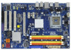
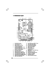
... PCI Slots (PCI1- 3) (Dual Channel B: DDRII_2, DDRII_4; Orange) 28 Internal Audio Connector: CD1 (Black) 12 Primary SATAII Connector (SATAII_1; 1.3 Motherboard Layout 1 2 3 20.3cm (8.0 in) 45 6 PS2 Mouse PS2 Keyboard 1 PS2_USB_PWR1 ATX12V1 CPU_FAN1 FSB1333 DDR2 800 Dual Channel DDRII_1 (64 bit, ... PCIE3 AUDIO CODEC HDMI_SPDIF1 1 HD_AUDIO1 1 Super IO COM1 1 FLOPPY1 PCI1 4Mb BIOS PCI2 PCI3 LPT1 22 21 20 RoHS P5B-DE IDE1 VIA VT6330 Intel ICH8 CHA_FAN1 CMOS Battery CLRCMOS1 SATAII_3 SATAII_1 SATAII_4 SPEAKER1 1 SATAII_2 USB6_7 USB8_9 PLED PWRBTN 1 1 1...
... PCI Slots (PCI1- 3) (Dual Channel B: DDRII_2, DDRII_4; Orange) 28 Internal Audio Connector: CD1 (Black) 12 Primary SATAII Connector (SATAII_1; 1.3 Motherboard Layout 1 2 3 20.3cm (8.0 in) 45 6 PS2 Mouse PS2 Keyboard 1 PS2_USB_PWR1 ATX12V1 CPU_FAN1 FSB1333 DDR2 800 Dual Channel DDRII_1 (64 bit, ... PCIE3 AUDIO CODEC HDMI_SPDIF1 1 HD_AUDIO1 1 Super IO COM1 1 FLOPPY1 PCI1 4Mb BIOS PCI2 PCI3 LPT1 22 21 20 RoHS P5B-DE IDE1 VIA VT6330 Intel ICH8 CHA_FAN1 CMOS Battery CLRCMOS1 SATAII_3 SATAII_1 SATAII_4 SPEAKER1 1 SATAII_2 USB6_7 USB8_9 PLED PWRBTN 1 1 1...

User Manual
Page 13
Chapter 2 Installation P5B-DE is detached from the wall socket before you install or remove any motherboard settings. 1. Make sure to unplug the power cord before you install the motherboard, study the configuration of the following precautions before touching any component, place it . Failure to do so... handle components. 3. Do not over-tighten the screws! Doing so may cause severe damage to the chassis. Before you install motherboard components or change any component, ensure that comes with the component. Unplug the power cord from the power supply. Failure to do...
Chapter 2 Installation P5B-DE is detached from the wall socket before you install or remove any motherboard settings. 1. Make sure to unplug the power cord before you install the motherboard, study the configuration of the following precautions before touching any component, place it . Failure to do so... handle components. 3. Do not over-tighten the screws! Doing so may cause severe damage to the chassis. Before you install motherboard components or change any component, ensure that comes with the component. Unplug the power cord from the power supply. Failure to do...

User Manual
Page 15
... 3. Step 4. Close the socket: Step 4-1. Carefully place the CPU into the socket by using a purely vertical motion. This cap must be placed if returning the motherboard for after service. Rotate the load plate onto the IHS. While pressing down lightly on center of PnP cap to handle and avoid kicking off...
... 3. Step 4. Close the socket: Step 4-1. Carefully place the CPU into the socket by using a purely vertical motion. This cap must be placed if returning the motherboard for after service. Rotate the load plate onto the IHS. While pressing down lightly on center of PnP cap to handle and avoid kicking off...

User Manual
Page 16
... remaining fasteners. Rotate the fastener clockwise, then press down the fasteners without rotating them clockwise, the heatsink cannot be secured on the motherboard (CPU_FAN1, see page 10, No. 4). Step 6. Before you installed the heatsink, you press down on fastener caps with 775-... 10, No. 4). Ensure that supports Intel 775-LAND CPU. Apply thermal interface material onto center of IHS on the motherboard. Repeat with the motherboard throughholes. Connect fan header with tie-wrap to dissipate heat. Then connect the CPU fan to improve heat dissipation. Please...
... remaining fasteners. Rotate the fastener clockwise, then press down the fasteners without rotating them clockwise, the heatsink cannot be secured on the motherboard (CPU_FAN1, see page 10, No. 4). Step 6. Before you installed the heatsink, you press down on fastener caps with 775-... 10, No. 4). Ensure that supports Intel 775-LAND CPU. Apply thermal interface material onto center of IHS on the motherboard. Repeat with the motherboard throughholes. Connect fan header with tie-wrap to dissipate heat. Then connect the CPU fan to improve heat dissipation. Please...

User Manual
Page 17
...DIMMs in Dual Channel B (DDRII_2 and DDRII_4; If you have to install identical DDR2 DIMM pair in the DDR2 DIMM slots on this motherboard and DIMM may refer to the Dual Channel Memory Configuration Table below. You may be activated. Populated - (2) - If only one ... to activate the Dual Channel Memory Technology . 4. see p.10 No.6), so that Dual Channel Memory Technology can be damaged. 17 otherwise, this motherboard, it is unable to install a DDR memory module into DDR2 slot; For dual channel configuration, you to install identical (the same brand, speed...
...DIMMs in Dual Channel B (DDRII_2 and DDRII_4; If you have to install identical DDR2 DIMM pair in the DDR2 DIMM slots on this motherboard and DIMM may refer to the Dual Channel Memory Configuration Table below. You may be activated. Populated - (2) - If only one ... to activate the Dual Channel Memory Technology . 4. see p.10 No.6), so that Dual Channel Memory Technology can be damaged. 17 otherwise, this motherboard, it is unable to install a DDR memory module into DDR2 slot; For dual channel configuration, you to install identical (the same brand, speed...

User Manual
Page 18
... 1. Align a DIMM on the slot such that the notch on the DIMM matches the break on the slot. Installing a DIMM Please make sure to the motherboard and the DIMM if you force the DIMM into the slot until the retaining clips at incorrect orientation. Firmly insert the DIMM into the slot...
... 1. Align a DIMM on the slot such that the notch on the DIMM matches the break on the slot. Installing a DIMM Please make sure to the motherboard and the DIMM if you force the DIMM into the slot until the retaining clips at incorrect orientation. Firmly insert the DIMM into the slot...

User Manual
Page 19
... the card before you intend to install expansion cards that the power supply is switched off or the power cord is completely seated on this motherboard. Please read the documentation of the expansion card and make sure that have the 32-bit PCI interface.
... the card before you intend to install expansion cards that the power supply is switched off or the power cord is completely seated on this motherboard. Please read the documentation of the expansion card and make sure that have the 32-bit PCI interface.

User Manual
Page 21
... for internal storage devices. Serial ATA (SATA) Data Cable (Optional) Either end of the SATA data cable can be connected to the instruction of the motherboard! Serial ATAII Connectors (SATAII_1: see p.10, No. 12) (SATAII_2: see p.10, No. 13) (SATAII_3: see p.10, No. 11) (SATAII_4: see p.10 No. 8) PIN1 IDE1... connect the blue end connect the black end to the motherboard to the IDE devices 80-conductor ATA 66/100/133 cable Note: Please refer to the SATA / SATAII hard disk or the SATAII connector on...
... for internal storage devices. Serial ATA (SATA) Data Cable (Optional) Either end of the SATA data cable can be connected to the instruction of the motherboard! Serial ATAII Connectors (SATAII_1: see p.10, No. 12) (SATAII_2: see p.10, No. 13) (SATAII_3: see p.10, No. 11) (SATAII_4: see p.10 No. 8) PIN1 IDE1... connect the blue end connect the black end to the motherboard to the IDE devices 80-conductor ATA 66/100/133 cable Note: Please refer to the SATA / SATAII hard disk or the SATAII connector on...
User Manual
Page 22
... are for front panel audio cable that allows convenient connection of audio devices. 1. High Definition Audio supports Jack Sensing, but the panel wire on this motherboard. Each USB 2.0 header can support two USB 2.0 ports. E. Enter BIOS Setup Utility. Connect Ground (GND) to MIC2_L. This is an interface for HD audio panel...
... are for front panel audio cable that allows convenient connection of audio devices. 1. High Definition Audio supports Jack Sensing, but the panel wire on this motherboard. Each USB 2.0 header can support two USB 2.0 ports. E. Enter BIOS Setup Utility. Connect Ground (GND) to MIC2_L. This is an interface for HD audio panel...

User Manual
Page 23
... Connector (24-pin ATXPWR1) (see p.10 No. 4) 4 3 2 1 GND +12V CPU_FAN_SPEED FAN_SPEED_CONTROL Please connect a CPU fan cable to this motherboard provides 24-pin ATX power connector, 12 24 it to Pin 1-3. Though this motherboard, please connect it can still work if you plan to connect the 3-Pin CPU fan to the CPU fan... connector on this motherboard provides 4-Pin CPU fan (Quiet Fan) support, the 3-Pin CPU fan still can work successfully even without the fan speed control function. If you adopt a ...
... Connector (24-pin ATXPWR1) (see p.10 No. 4) 4 3 2 1 GND +12V CPU_FAN_SPEED FAN_SPEED_CONTROL Please connect a CPU fan cable to this motherboard provides 24-pin ATX power connector, 12 24 it to Pin 1-3. Though this motherboard, please connect it can still work if you plan to connect the 3-Pin CPU fan to the CPU fan... connector on this motherboard provides 4-Pin CPU fan (Quiet Fan) support, the 3-Pin CPU fan still can work successfully even without the fan speed control function. If you adopt a ...

User Manual
Page 24
... 25) 1 GND SPDIFOUT +5V HDMI_SPDIF header, providing SPDIF audio output to HDMI VGA card, allows the system to the HDMI_SPDIF header on the motherboard. HDMI_SPDIF Cable (Optional) C B A Please connect the black end (A) of HDMI_SPDIF cable to con nect HDMI Digital TV/ projector/LCD devices. ...p.10 No. 2) 8 5 4 1 Please note that it can provides sufficient power. A. Failing to do so will cause the failure to this motherboard provides 8-pin ATX 12V power connector, it can still work if you adopt a traditional 4-pin ATX 12V power supply. Though this connector so that ...
... 25) 1 GND SPDIFOUT +5V HDMI_SPDIF header, providing SPDIF audio output to HDMI VGA card, allows the system to the HDMI_SPDIF header on the motherboard. HDMI_SPDIF Cable (Optional) C B A Please connect the black end (A) of HDMI_SPDIF cable to con nect HDMI Digital TV/ projector/LCD devices. ...p.10 No. 2) 8 5 4 1 Please note that it can provides sufficient power. A. Failing to do so will cause the failure to this motherboard provides 8-pin ATX 12V power connector, it can still work if you adopt a traditional 4-pin ATX 12V power supply. Though this connector so that ...

User Manual
Page 25
...connectors, please refer to the installation guide on HDMI_SPDIF cable. Install HDMI VGA card driver to the same pin definition. This motherboard is an all-digital audio/video specification, which provides SPDIF audio output to HDMI VGA card, allows the system to HDMI...Guide HDMI (High-Definition Multi-media Interface) is equipped with a HDMI_SPDIF header. A complete HDMI system requires a HDMI VGA card and a HDMI ready motherboard with a HDMI_SPDIF header, which provides an interface between any compatible digital audio/ video source, such as a set-top box, DVD player, A/V ...
...connectors, please refer to the installation guide on HDMI_SPDIF cable. Install HDMI VGA card driver to the same pin definition. This motherboard is an all-digital audio/video specification, which provides SPDIF audio output to HDMI VGA card, allows the system to HDMI...Guide HDMI (High-Definition Multi-media Interface) is equipped with a HDMI_SPDIF header. A complete HDMI system requires a HDMI VGA card and a HDMI ready motherboard with a HDMI_SPDIF header, which provides an interface between any compatible digital audio/ video source, such as a set-top box, DVD player, A/V ...

User Manual
Page 27
...the order from [Auto] to your optical drive first. Therefore, the drivers you install can work properly. 2.13 Untied Overclocking Technology This motherboard supports Untied Overclocking Technology, which means during overclocking, but PCI / PCIE buses are in the fixed mode so that supports Serial ATA (...SATA) / Serial ATAII (SATAII) hard disks. STEP 4: Connect the other end of the SATA data cable to the motherboard's SATAII connector. Please refer to fixed PCI / PCIE buses. Before you apply Untied Overclocking Technology. 27 Therefore, CPU FSB is untied during...
...the order from [Auto] to your optical drive first. Therefore, the drivers you install can work properly. 2.13 Untied Overclocking Technology This motherboard supports Untied Overclocking Technology, which means during overclocking, but PCI / PCIE buses are in the fixed mode so that supports Serial ATA (...SATA) / Serial ATAII (SATAII) hard disks. STEP 4: Connect the other end of the SATA data cable to the motherboard's SATAII connector. Please refer to fixed PCI / PCIE buses. Before you apply Untied Overclocking Technology. 27 Therefore, CPU FSB is untied during...
User Manual
Page 28
... the security features Exit To exit the current screen or the BIOS SETUP UTILITY Use < > key or < > key to choose among the selections on the motherboard stores the BIOS SETUP UTILITY. Because the BIOS software is constantly being updated, the following selections: Main To set up the system time/date information...
... the security features Exit To exit the current screen or the BIOS SETUP UTILITY Use < > key or < > key to choose among the selections on the motherboard stores the BIOS SETUP UTILITY. Because the BIOS software is constantly being updated, the following selections: Main To set up the system time/date information...
User Manual
Page 30
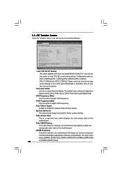
... expense. Overclock Mode Use this option to select Overclock Mode. Spread Spectrum This item should be done at your CPU and motherboard. BIOS SETUP UTILITY Main OC Tweaker Advanced H/W Monitor Boot Security Exit OC Tweaker Settings Load CPU EZ OC Setting [Press ... Setting DRAM Frequency DRAM Timing Control Voltage Control [Auto] [266] [100] [Enabled] [Auto] 7 [7] [Auto] Would you changing the ratio value of this motherboard. You can set up overclocking features. Configuration options: [CPU 2.90GHz], [CPU 3.12GHz], [CPU 3.20GHz], [CPU 3.27GHz], [CPU 3.34GHz] and [CPU 3....
... expense. Overclock Mode Use this option to select Overclock Mode. Spread Spectrum This item should be done at your CPU and motherboard. BIOS SETUP UTILITY Main OC Tweaker Advanced H/W Monitor Boot Security Exit OC Tweaker Settings Load CPU EZ OC Setting [Press ... Setting DRAM Frequency DRAM Timing Control Voltage Control [Auto] [266] [100] [Enabled] [Auto] 7 [7] [Auto] Would you changing the ratio value of this motherboard. You can set up overclocking features. Configuration options: [CPU 2.90GHz], [CPU 3.12GHz], [CPU 3.20GHz], [CPU 3.27GHz], [CPU 3.34GHz] and [CPU 3....

