
User Manual
Page 1
All rights reserved. 1 P5B-DE User Manual Version 1.0 Published August 2009 Copyright©2009 ASRock INC.
All rights reserved. 1 P5B-DE User Manual Version 1.0 Published August 2009 Copyright©2009 ASRock INC.

User Manual
Page 2
..., USA, please follow the related regulations in Perchlorate Best Management Practices (BMP) regulations passed by the California Legislature. With respect to the contents of this manual, ASRock does not provide warranty of any kind, either expressed or implied, including but not limited to the implied warranties or conditions of merchantability or fitness...
..., USA, please follow the related regulations in Perchlorate Best Management Practices (BMP) regulations passed by the California Legislature. With respect to the contents of this manual, ASRock does not provide warranty of any kind, either expressed or implied, including but not limited to the implied warranties or conditions of merchantability or fitness...

User Manual
Page 5
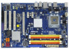
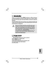
... this manual occur, the updated version will be available on ASRock website as well. www.asrock.com/support/index.asp 1.1 Package Contents ASRock P5B-DE Motherboard (ATX Form Factor: 12.0-in x 8.0-in, 30.5 cm x 20.3 cm) ASRock P5B-DE Quick Installation Guide ASRock P5B-DE Support ... I/O Panel Shield 5 In this motherboard, please visit our website for purchasing ASRock P5B-DE motherboard, a reliable motherboard produced under ASRock's consistently stringent quality control. ASRock website http://www.asrock.com If you for specific information about the model you are using. You...
... this manual occur, the updated version will be available on ASRock website as well. www.asrock.com/support/index.asp 1.1 Package Contents ASRock P5B-DE Motherboard (ATX Form Factor: 12.0-in x 8.0-in, 30.5 cm x 20.3 cm) ASRock P5B-DE Quick Installation Guide ASRock P5B-DE Support ... I/O Panel Shield 5 In this motherboard, please visit our website for purchasing ASRock P5B-DE motherboard, a reliable motherboard produced under ASRock's consistently stringent quality control. ASRock website http://www.asrock.com If you for specific information about the model you are using. You...

User Manual
Page 16
... need to spray thermal interface material between the CPU and the heatsink to improve heat dissipation. For proper installation, please kindly refer to the instruction manuals of heatsink and cooling fan compliant with 775-Pin socket that the CPU and the heatsink are oriented on side closest to the CPU fan...
... need to spray thermal interface material between the CPU and the heatsink to improve heat dissipation. For proper installation, please kindly refer to the instruction manuals of heatsink and cooling fan compliant with 775-Pin socket that the CPU and the heatsink are oriented on side closest to the CPU fan...
User Manual
Page 22
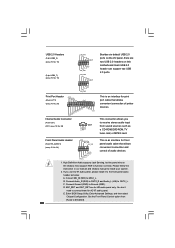
... below: A. This is an interface for print port cable that allows convenient connection and control of printer devices. Please follow the instruction in our manual and chassis manual to MIC2_L. Connect Mic_IN (MIC) to install your system. 2. Enter Advanced Settings, and then select Chipset Configuration. High Definition Audio supports Jack Sensing, but...
... below: A. This is an interface for print port cable that allows convenient connection and control of printer devices. Please follow the instruction in our manual and chassis manual to MIC2_L. Connect Mic_IN (MIC) to install your system. 2. Enter Advanced Settings, and then select Chipset Configuration. High Definition Audio supports Jack Sensing, but...

User Manual
Page 25
... in advance. Step 5. Step 1. Connect the HDMI output connector on this motherboard. Install HDMI VGA card driver to the user manual of HDMI_SPDIF cable to page 24. This motherboard is an all-digital audio/video specification, which provides SPDIF audio output to HDMI ... guide on HDMI_SPDIF cable. Please refer to your system. 25 Step 2. Please choose the appropriate white end according to the VGA card user manual for detailed connection procedures. white end (2-pin) (B) white end (3-pin) (C) Step 4. Step 3. Please refer to the HDMI_SPDIF connector of...
... in advance. Step 5. Step 1. Connect the HDMI output connector on this motherboard. Install HDMI VGA card driver to the user manual of HDMI_SPDIF cable to page 24. This motherboard is an all-digital audio/video specification, which provides SPDIF audio output to HDMI ... guide on HDMI_SPDIF cable. Please refer to your system. 25 Step 2. Please choose the appropriate white end according to the VGA card user manual for detailed connection procedures. white end (2-pin) (B) white end (3-pin) (C) Step 4. Step 3. Please refer to the HDMI_SPDIF connector of...

User Manual
Page 33
...options: [Auto], [1.272V] and [1.319V]. The default value is [Auto]. SB Voltage Use this to select SB Voltage. Configuration options: [Auto] and [Manual]. DRAM Voltage Use this to select DRAM Voltage. The default value is [Auto]. 33 The default value is [Auto]. CPU Voltage Use this to select... OC Tweaker Voltage Control CPU Voltage DRAM Voltage NB Voltage VTT Voltage SB Voltage [Auto] [Auto] [Auto] [Auto] [Auto] Options Auto Manual +F1 F9 F10 ESC Select Screen Select Item Change Option General Help Load Defaults Save and Exit Exit v02.54 (C) Copyright 1985-2005, American ...
...options: [Auto], [1.272V] and [1.319V]. The default value is [Auto]. SB Voltage Use this to select SB Voltage. Configuration options: [Auto] and [Manual]. DRAM Voltage Use this to select DRAM Voltage. The default value is [Auto]. 33 The default value is [Auto]. CPU Voltage Use this to select... OC Tweaker Voltage Control CPU Voltage DRAM Voltage NB Voltage VTT Voltage SB Voltage [Auto] [Auto] [Auto] [Auto] [Auto] Options Auto Manual +F1 F9 F10 ESC Select Screen Select Item Change Option General Help Load Defaults Save and Exit Exit v02.54 (C) Copyright 1985-2005, American ...
Quick Installation Guide
Page 5
..., the updated version will be found in the user manual presented in , 30.5 cm x 20.3 cm) ASRock P5B-DE Quick Installation Guide ASRock P5B-DE Support CD One 80-conductor Ultra ATA 66/100/133 IDE Ribbon Cable One Serial ATA (SATA) Data Cable (Optional) One I/O Panel Shield 5 ASRock P5B-DE Motherboard English Because the motherboard specifications and the BIOS...
..., the updated version will be found in the user manual presented in , 30.5 cm x 20.3 cm) ASRock P5B-DE Quick Installation Guide ASRock P5B-DE Support CD One 80-conductor Ultra ATA 66/100/133 IDE Ribbon Cable One Serial ATA (SATA) Data Cable (Optional) One I/O Panel Shield 5 ASRock P5B-DE Motherboard English Because the motherboard specifications and the BIOS...

Quick Installation Guide
Page 8
...174; environment. We are not responsible for proper connection. 7. About the setting of "Hyper Threading Technology", please check page 35 of "User Manual" in the support CD to adjust your hardware devices to read "Untied Overclocking Technology" on page 3 for possible damage caused by hardware monitor function... disk to SATAII mode. It should be less than 4GB for the reservation for the CPU FSB frequency and its corre- ASRock website: http://www.asrock.com English 8 ASRock P5B-DE Motherboard Overclocking may be done at your system. Please read the installation guide of...
...174; environment. We are not responsible for proper connection. 7. About the setting of "Hyper Threading Technology", please check page 35 of "User Manual" in the support CD to adjust your hardware devices to read "Untied Overclocking Technology" on page 3 for possible damage caused by hardware monitor function... disk to SATAII mode. It should be less than 4GB for the reservation for the CPU FSB frequency and its corre- ASRock website: http://www.asrock.com English 8 ASRock P5B-DE Motherboard Overclocking may be done at your system. Please read the installation guide of...

Quick Installation Guide
Page 12
... motherboard (CPU_FAN1, see page 2, No. 4). Place the heatsink onto the socket. Connect fan header with fan operation or contact other components. 12 ASRock P5B-DE Motherboard Secure excess cable with tie-wrap to handle and avoid kicking off the PnP cap. 2. 1. Step 4. Rotate the load plate onto the IHS...ensure cable does not interfere with the CPU fan connector on the motherboard. Ensure fan cables are oriented on side closest to the instruction manuals of the heatsink for after service. Repeat with load plate tab under retention tab of load lever. 2.2 Installation of CPU Fan and...
... motherboard (CPU_FAN1, see page 2, No. 4). Place the heatsink onto the socket. Connect fan header with fan operation or contact other components. 12 ASRock P5B-DE Motherboard Secure excess cable with tie-wrap to handle and avoid kicking off the PnP cap. 2. 1. Step 4. Rotate the load plate onto the IHS...ensure cable does not interfere with the CPU fan connector on the motherboard. Ensure fan cables are oriented on side closest to the instruction manuals of the heatsink for after service. Repeat with load plate tab under retention tab of load lever. 2.2 Installation of CPU Fan and...

Quick Installation Guide
Page 18
... (9-pin HD_AUDIO1) (see p.2 No. 24) This connector allows you use AC'97 audio panel, please install it to [Enabled]. 18 ASRock P5B-DE Motherboard English Connect Ground (GND) to receive stereo audio input CD1 from [Auto] to the front panel audio header as a CD-ROM,... This is an interface for print port cable that allows convenient connection and control of printer devices. Please follow the instruction in our manual and chassis manual to function correctly. Connect Mic_IN (MIC) to OUT2_L. Connect Audio_R (RIN) to OUT2_R and Audio_L (LIN) to MIC2_L. B. If...
... (9-pin HD_AUDIO1) (see p.2 No. 24) This connector allows you use AC'97 audio panel, please install it to [Enabled]. 18 ASRock P5B-DE Motherboard English Connect Ground (GND) to receive stereo audio input CD1 from [Auto] to the front panel audio header as a CD-ROM,... This is an interface for print port cable that allows convenient connection and control of printer devices. Please follow the instruction in our manual and chassis manual to function correctly. Connect Mic_IN (MIC) to OUT2_L. Connect Audio_R (RIN) to OUT2_R and Audio_L (LIN) to MIC2_L. B. If...

Quick Installation Guide
Page 22
... / Win7. If the Main Menu does not appear automatically, locate and doubleclick on the motherboard stores BIOS Setup Utility. When you wish to the User Manual (PDF file) contained in your CDROM drive. To begin using the Support CD, insert the CD into your computer. otherwise, POST continues with the motherboard... scroll through its test routines. If you start up the computer, please press during the Power-On-Self-Test (POST) to display the menus. 22 ASRock P5B-DE Motherboard English
... / Win7. If the Main Menu does not appear automatically, locate and doubleclick on the motherboard stores BIOS Setup Utility. When you wish to the User Manual (PDF file) contained in your CDROM drive. To begin using the Support CD, insert the CD into your computer. otherwise, POST continues with the motherboard... scroll through its test routines. If you start up the computer, please press during the Power-On-Self-Test (POST) to display the menus. 22 ASRock P5B-DE Motherboard English
