
User Manual
Page 6
... Codec) - Dual Channel DDR2 Memory Technology (see CAUTION 7) - 1 x ATA133 IDE connector (supports 2 x IDE devices) - 1 x Floppy connector - 1 x Print port header - 1 x COM port header - 1 x HDMI_SPDIF header 6 LGA 775 for RAID and "Hot Plug" functions) (see CAUTION 3) - 4 x DDR2 DIMM slots - Southbridge: Intel® ICH8 - HD Audio Jack: Side Speaker/Rear Speaker/Central/Bass/ Line...
... Codec) - Dual Channel DDR2 Memory Technology (see CAUTION 7) - 1 x ATA133 IDE connector (supports 2 x IDE devices) - 1 x Floppy connector - 1 x Print port header - 1 x COM port header - 1 x HDMI_SPDIF header 6 LGA 775 for RAID and "Hot Plug" functions) (see CAUTION 3) - 4 x DDR2 DIMM slots - Southbridge: Intel® ICH8 - HD Audio Jack: Side Speaker/Rear Speaker/Central/Bass/ Line...
User Manual
Page 10
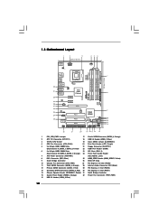
... Chipset PCIE3 AUDIO CODEC HDMI_SPDIF1 1 HD_AUDIO1 1 Super IO COM1 1 FLOPPY1 PCI1 4Mb BIOS PCI2 PCI3 LPT1 22 21 20 RoHS P5B-DE IDE1 VIA VT6330 Intel ICH8 CHA_FAN1 CMOS Battery CLRCMOS1 SATAII_3 SATAII_1 SATAII_4 SPEAKER1 1 SATAII_2 USB6_7 USB8_9 PLED PWRBTN 1 1 1 1 ... Slots 23 PCI Slots (PCI1- 3) (Dual Channel B: DDRII_2, DDRII_4; Orange) 2 ATX 12V Connector (ATX12V1) 18 USB 2.0 Header (USB6_7, Blue) 3 775-Pin CPU Socket 19 Clear CMOS Jumper (CLRCMOS1) 4 CPU Fan Connector (CPU_FAN1) 20 Print Port Header (LPT1, Purple) 5 2 x 240-pin DDR2 DIMM ...
... Chipset PCIE3 AUDIO CODEC HDMI_SPDIF1 1 HD_AUDIO1 1 Super IO COM1 1 FLOPPY1 PCI1 4Mb BIOS PCI2 PCI3 LPT1 22 21 20 RoHS P5B-DE IDE1 VIA VT6330 Intel ICH8 CHA_FAN1 CMOS Battery CLRCMOS1 SATAII_3 SATAII_1 SATAII_4 SPEAKER1 1 SATAII_2 USB6_7 USB8_9 PLED PWRBTN 1 1 1 1 ... Slots 23 PCI Slots (PCI1- 3) (Dual Channel B: DDRII_2, DDRII_4; Orange) 2 ATX 12V Connector (ATX12V1) 18 USB 2.0 Header (USB6_7, Blue) 3 775-Pin CPU Socket 19 Clear CMOS Jumper (CLRCMOS1) 4 CPU Fan Connector (CPU_FAN1) 20 Print Port Header (LPT1, Purple) 5 2 x 240-pin DDR2 DIMM ...

User Manual
Page 14
... notch orientation key notch Pin1 alignment key alignment key 775-LAND CPU 14 775-Pin Socket black line black line 2.3 CPU Installation For the installation of Intel 775-LAND CPU, please follow the steps below. 775-Pin Socket Overview Before you insert the 775-LAND CPU into the socket if above situation is ... load lever to insert the CPU into the socket, please check if the CPU surface is unclean or if there is found. Insert the 775-LAND CPU: Step 2-1. Open the socket: CPU Marked Corner Step 1-1. Step 1-2. Step 1-3. Locate Pin1 and the two orientation key notches.
... notch orientation key notch Pin1 alignment key alignment key 775-LAND CPU 14 775-Pin Socket black line black line 2.3 CPU Installation For the installation of Intel 775-LAND CPU, please follow the steps below. 775-Pin Socket Overview Before you insert the 775-LAND CPU into the socket if above situation is ... load lever to insert the CPU into the socket, please check if the CPU surface is unclean or if there is found. Insert the 775-LAND CPU: Step 2-1. Open the socket: CPU Marked Corner Step 1-1. Step 1-2. Step 1-3. Locate Pin1 and the two orientation key notches.

User Manual
Page 16
... with remaining fasteners. Step 6. Before you installed the heatsink, you press down on side closest to dissipate heat. Below is equipped with 775-Pin socket that the CPU and the heatsink are oriented on fastener caps with thumb to the CPU_FAN connector (CPU_FAN1, see page 10, ...CPU fan and heatsink. 2.4 Installation of CPU Fan and Heatsink This motherboard is an example to improve heat dissipation. Ensure that supports Intel 775-LAND CPU. For proper installation, please kindly refer to ensure cable does not interfere with fan operation or contact other . Step 2. Step...
... with remaining fasteners. Step 6. Before you installed the heatsink, you press down on side closest to dissipate heat. Below is equipped with 775-Pin socket that the CPU and the heatsink are oriented on fastener caps with thumb to the CPU_FAN connector (CPU_FAN1, see page 10, ...CPU fan and heatsink. 2.4 Installation of CPU Fan and Heatsink This motherboard is an example to improve heat dissipation. Ensure that supports Intel 775-LAND CPU. For proper installation, please kindly refer to ensure cable does not interfere with fan operation or contact other . Step 2. Step...

Quick Installation Guide
Page 2
... Connector: CD1 (Black) 12 Primary SATAII Connector (SATAII_1; Orange) 2 ATX 12V Connector (ATX12V1) 18 USB 2.0 Header (USB6_7, Blue) 3 775-Pin CPU Socket 19 Clear CMOS Jumper (CLRCMOS1) 4 CPU Fan Connector (CPU_FAN1) 20 Print Port Header (LPT1, Purple) 5 2 x 240-...Purple) 31 North Bridge Controller 15 System Panel Header (PANEL1, Orange) 32 Power Fan Connector (PWR_FAN1) 16 USB 2.0 Header (USB8_9, Blue) 2 ASRock P5B-DE Motherboard Red) 29 PCI Express x1 Slot (PCIE2) 13 Secondary SATAII Connector (SATAII_2; Orange) 24 Front Panel Audio Header 7 ATX Power Connector (...
... Connector: CD1 (Black) 12 Primary SATAII Connector (SATAII_1; Orange) 2 ATX 12V Connector (ATX12V1) 18 USB 2.0 Header (USB6_7, Blue) 3 775-Pin CPU Socket 19 Clear CMOS Jumper (CLRCMOS1) 4 CPU Fan Connector (CPU_FAN1) 20 Print Port Header (LPT1, Purple) 5 2 x 240-...Purple) 31 North Bridge Controller 15 System Panel Header (PANEL1, Orange) 32 Power Fan Connector (PWR_FAN1) 16 USB 2.0 Header (USB8_9, Blue) 2 ASRock P5B-DE Motherboard Red) 29 PCI Express x1 Slot (PCIE2) 13 Secondary SATAII Connector (SATAII_2; Orange) 24 Front Panel Audio Header 7 ATX Power Connector (...
Quick Installation Guide
Page 6
LGA 775 for RAID and "Hot Plug" functions) (see CAUTION 7) - 1 x ATA133 IDE connector (supports 2 x IDE devices) - 1 x Floppy connector - 1 x Print port header - 1 x COM port header - 1 x HDMI_SPDIF header ASRock P5B-DE Motherboard English Southbridge: Intel® ICH8 - Dual Channel DDR2 Memory Technology (see CAUTION 5) - 1 x PCI Express x16 slot - 2 x PCI Express x1 slots - 3 x PCI slots - 7.1 CH Windows&#...
LGA 775 for RAID and "Hot Plug" functions) (see CAUTION 7) - 1 x ATA133 IDE connector (supports 2 x IDE devices) - 1 x Floppy connector - 1 x Print port header - 1 x COM port header - 1 x HDMI_SPDIF header ASRock P5B-DE Motherboard English Southbridge: Intel® ICH8 - Dual Channel DDR2 Memory Technology (see CAUTION 5) - 1 x PCI Express x16 slot - 2 x PCI Express x1 slots - 3 x PCI slots - 7.1 CH Windows&#...

Quick Installation Guide
Page 10
...to do not touch the ICs. 4. 2. Installation Pre-installation Precautions Take note of Intel 775-LAND CPU, please follow the steps below. 775-Pin Socket Overview Before you handle components. 3. To avoid damaging the motherboard components due to... use a grounded wrist strap or touch a safety grounded object before you insert the 775-LAND CPU into the socket if above situation is any motherboard settings. 1. Failure to the motherboard, peripherals, and...found. Otherwise, the CPU will be seriously damaged. 10 ASRock P5B-DE Motherboard English
...to do not touch the ICs. 4. 2. Installation Pre-installation Precautions Take note of Intel 775-LAND CPU, please follow the steps below. 775-Pin Socket Overview Before you handle components. 3. To avoid damaging the motherboard components due to... use a grounded wrist strap or touch a safety grounded object before you insert the 775-LAND CPU into the socket if above situation is any motherboard settings. 1. Failure to the motherboard, peripherals, and...found. Otherwise, the CPU will be seriously damaged. 10 ASRock P5B-DE Motherboard English

Quick Installation Guide
Page 11
...while pressing on the hook to fully open position at approximately 135 degrees. Rotate the load lever to clear retention tab. Step 1-3. Insert the 775-LAND CPU: Step 2-1. Locate Pin1 and the two orientation key notches. Carefully place the CPU into the socket by depressing down and out ... finger and thumb to support the load plate edge, engage PnP cap with the two alignment keys of PnP cap to assist in removal. 11 ASRock P5B-DE Motherboard English Step 2-4. Step 1. Step 2. Orient the CPU with black lines. Step 2-3. Step 3. Verify that the CPU is within the socket and ...
...while pressing on the hook to fully open position at approximately 135 degrees. Rotate the load lever to clear retention tab. Step 1-3. Insert the 775-LAND CPU: Step 2-1. Locate Pin1 and the two orientation key notches. Carefully place the CPU into the socket by depressing down and out ... finger and thumb to support the load plate edge, engage PnP cap with the two alignment keys of PnP cap to assist in removal. 11 ASRock P5B-DE Motherboard English Step 2-4. Step 1. Step 2. Orient the CPU with black lines. Step 2-3. Step 3. Verify that the CPU is within the socket and ...

Quick Installation Guide
Page 12
Close the socket: Step 4-1. While pressing down the fasteners without rotating them clockwise, the heatsink cannot be placed if returning the motherboard for 775-LAND CPU. English Step 2. Step 6. Step 4. Secure load lever with the CPU fan connector on the motherboard. Step 3. Step 4-3. Step 4. Step 5. 1. Apply thermal ... It is an example to ensure cable does not interfere with the motherboard throughholes. Align fasteners with fan operation or contact other components. 12 ASRock P5B-DE Motherboard Place the heatsink onto the socket.
Close the socket: Step 4-1. While pressing down the fasteners without rotating them clockwise, the heatsink cannot be placed if returning the motherboard for 775-LAND CPU. English Step 2. Step 6. Step 4. Secure load lever with the CPU fan connector on the motherboard. Step 3. Step 4-3. Step 4. Step 5. 1. Apply thermal ... It is an example to ensure cable does not interfere with the motherboard throughholes. Align fasteners with fan operation or contact other components. 12 ASRock P5B-DE Motherboard Place the heatsink onto the socket.