User Manual
Page 4
... 3.4 Advanced Screen 53 3.4.1 CPU Configuration 54 3.4.2 Chipset Configuration 56 3.4.3 ACPI Configuration 57 3.4.4 IDE Configuration 58 3.4.5 PCIPnP Configuration 60 3.4.6 Floppy Configuration 61 3.4.7 Super IO Configuration 61 3.4.8 USB Configuration 62 3.5 Hardware Health Event Monitoring Screen 63 3.6 Boot Screen 64 3.6.1 Boot Settings Configuration 64 3.7 Security Screen 65 3.8 Exit Screen 66 4 Software Support 67 4.1 Install...
... 3.4 Advanced Screen 53 3.4.1 CPU Configuration 54 3.4.2 Chipset Configuration 56 3.4.3 ACPI Configuration 57 3.4.4 IDE Configuration 58 3.4.5 PCIPnP Configuration 60 3.4.6 Floppy Configuration 61 3.4.7 Super IO Configuration 61 3.4.8 USB Configuration 62 3.5 Hardware Health Event Monitoring Screen 63 3.6 Boot Screen 64 3.6.1 Boot Settings Configuration 64 3.7 Security Screen 65 3.8 Exit Screen 66 4 Software Support 67 4.1 Install...
User Manual
Page 6
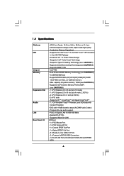
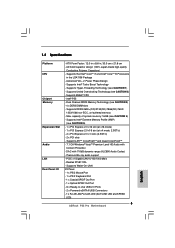
... DIMM slots - capacity of system memory: 16GB (see CAUTION 2) - PCIE x1 Gigabit LAN 10/100/1000 Mb/s - Intel® P55 - Supports DDR3 2600+(OC)/2133(OC)/1866(OC)/1600/ 1333/1066 non-ECC, un-buffered memory - 1.2 Specifications Platform CPU Chipset Memory Expansion... PS/2 Mouse Port - 1 x PS/2 Keyboard Port - 1 x Coaxial SPDIF Out Port - 1 x Optical SPDIF Out Port - 6 x Ready-to-Use USB 2.0 Ports - 2 x Powered eSATAII/USB Connectors - 1 x RJ-45 LAN Port with LED (ACT/LINK LED and SPEED LED) 6 Supports Untied Overclocking Technology (see CAUTION 4) - Supports Intel®...
... DIMM slots - capacity of system memory: 16GB (see CAUTION 2) - PCIE x1 Gigabit LAN 10/100/1000 Mb/s - Intel® P55 - Supports DDR3 2600+(OC)/2133(OC)/1866(OC)/1600/ 1333/1066 non-ECC, un-buffered memory - 1.2 Specifications Platform CPU Chipset Memory Expansion... PS/2 Mouse Port - 1 x PS/2 Keyboard Port - 1 x Coaxial SPDIF Out Port - 1 x Optical SPDIF Out Port - 6 x Ready-to-Use USB 2.0 Ports - 2 x Powered eSATAII/USB Connectors - 1 x RJ-45 LAN Port with LED (ACT/LINK LED and SPEED LED) 6 Supports Untied Overclocking Technology (see CAUTION 4) - Supports Intel®...
User Manual
Page 7
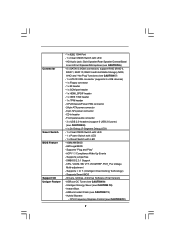
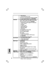
CPU/Chassis/Power FAN connector - 24 pin ATX power connector - 8 pin 12V power connector - Front panel audio connector - 3 x USB 2.0 headers (support 6 USB 2.0 ports) (see CAUTION 7) - 1 x ATA133 IDE connector (supports 2 x IDE devices) - 1 x Floppy connector - 1 x IR header - 1 x COM port header...BIOS - ACPI 1.1 Compliance Wake Up Events - SMBIOS 2.3.1 Support - AMI Legal BIOS - Drivers, Utilities, AntiVirus Software (Trial Version) - ASRock OC Tuner (see CAUTION 12) 7 Intelligent Energy Saver (see CAUTION 11) - Connector Smart Switch BIOS Feature Support CD Unique Feature - ...
CPU/Chassis/Power FAN connector - 24 pin ATX power connector - 8 pin 12V power connector - Front panel audio connector - 3 x USB 2.0 headers (support 6 USB 2.0 ports) (see CAUTION 7) - 1 x ATA133 IDE connector (supports 2 x IDE devices) - 1 x Floppy connector - 1 x IR header - 1 x COM port header...BIOS - ACPI 1.1 Compliance Wake Up Events - SMBIOS 2.3.1 Support - AMI Legal BIOS - Drivers, Utilities, AntiVirus Software (Trial Version) - ASRock OC Tuner (see CAUTION 12) 7 Intelligent Energy Saver (see CAUTION 11) - Connector Smart Switch BIOS Feature Support CD Unique Feature - ...
User Manual
Page 9
... entering operating systems first like MS-DOS or Windows®. Please visit our website for USB 2.0 works fine under 100 mA current consumption. Power Management for the operation procedures of Intelligent Energy Saver. ASRock website: http://www.asrock.com/feature/OCTuner/index.htm 10. Featuring an advanced proprietary hardware and software design, Intelligent...
... entering operating systems first like MS-DOS or Windows®. Please visit our website for USB 2.0 works fine under 100 mA current consumption. Power Management for the operation procedures of Intelligent Energy Saver. ASRock website: http://www.asrock.com/feature/OCTuner/index.htm 10. Featuring an advanced proprietary hardware and software design, Intelligent...

User Manual
Page 11
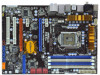
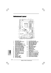
... 38 37 USB 2.0 T: USB0 B: USB1 USB 2.0 T: USB2 B: USB3 Top: IEEE 1394 USB 2.0 T: USB4 B: USB5 Top: RJ-45 Top: SIDE SPK Center: REAR SPK FRONT Bottom: CTR BASS MIC IN Top: LINE IN Center: Bottom: 36 LAN PHY 35 PWR_FAN1 CPU_FAN1 1394a CrossFireX PCIE1 P55 Pro EuP Ready PCI... Express 2.0 PCIE2 Dual Channel CHA_FAN3 34 33 32 31 Super I/O PCIE3 PCIE4 AUDIO CODEC RoHS HD_AUDIO1 CD1 COM1 1 1 1 HDMI_SPDIF1 PCI1 PCI2 FLOPPY1 30 29 28 27 Intel P55 IDE1 JMicron JMB363 VIA VT6308S 1 CLRCMOS1...
... 38 37 USB 2.0 T: USB0 B: USB1 USB 2.0 T: USB2 B: USB3 Top: IEEE 1394 USB 2.0 T: USB4 B: USB5 Top: RJ-45 Top: SIDE SPK Center: REAR SPK FRONT Bottom: CTR BASS MIC IN Top: LINE IN Center: Bottom: 36 LAN PHY 35 PWR_FAN1 CPU_FAN1 1394a CrossFireX PCIE1 P55 Pro EuP Ready PCI... Express 2.0 PCIE2 Dual Channel CHA_FAN3 34 33 32 31 Super I/O PCIE3 PCIE4 AUDIO CODEC RoHS HD_AUDIO1 CD1 COM1 1 1 1 HDMI_SPDIF1 PCI1 PCI2 FLOPPY1 30 29 28 27 Intel P55 IDE1 JMicron JMB363 VIA VT6308S 1 CLRCMOS1...
User Manual
Page 12
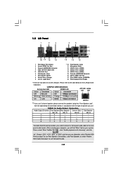
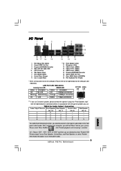
... 1.5 I/O Panel 1 2 3 4 5 69 7 10 8 11 18 17 16 15 14 13 12 1 PS/2 Mouse Port (Green) 2 Coaxial SPDIF Out Port 3 Powered eSATAII/USB Connector 4 IEEE 1394 Port (IEEE 1394) * 5 LAN RJ-45 Port 6 Side Speaker (Gray) 7 Rear Speaker (Black) 8 Central / Bass (Orange) 9 Line In (Light ...Blue) ** 10 11 12 13 14 15 16 17 18 Front Speaker (Lime) Microphone (Pink) USB 2.0 Ports (USB45) USB 2.0 Ports (USB23) USB 2.0 Ports (USB01) Powered eSATAII/USB Connector Optical SPDIF Out Port Clear CMOS Switch (CLRCBTN) PS/2 Keyboard Port (Purple) * There are allowed to select "Realtek...
... 1.5 I/O Panel 1 2 3 4 5 69 7 10 8 11 18 17 16 15 14 13 12 1 PS/2 Mouse Port (Green) 2 Coaxial SPDIF Out Port 3 Powered eSATAII/USB Connector 4 IEEE 1394 Port (IEEE 1394) * 5 LAN RJ-45 Port 6 Side Speaker (Gray) 7 Rear Speaker (Black) 8 Central / Bass (Orange) 9 Line In (Light ...Blue) ** 10 11 12 13 14 15 16 17 18 Front Speaker (Lime) Microphone (Pink) USB 2.0 Ports (USB45) USB 2.0 Ports (USB23) USB 2.0 Ports (USB01) Powered eSATAII/USB Connector Optical SPDIF Out Port Clear CMOS Switch (CLRCBTN) PS/2 Keyboard Port (Purple) * There are allowed to select "Realtek...
User Manual
Page 24
... pin2 and pin3 on these 2 pins. When the jumper cap is placed on pins, the jumper is placed on CLRCMOS1 for PS/2 +5V +5VSB or USB wake up the system first, and then shut it requires 2 Amp and higher standby current provided by power supply. The data in the Support CD...
... pin2 and pin3 on these 2 pins. When the jumper cap is placed on pins, the jumper is placed on CLRCMOS1 for PS/2 +5V +5VSB or USB wake up the system first, and then shut it requires 2 Amp and higher standby current provided by power supply. The data in the Support CD...

User Manual
Page 26
... wireless transmitting and receiving infrared module. 26 Serial ATA (SATA) Power Cable (Optional) connect to the SATA HDD power connector connect to the power supply USB 2.0 Headers (9-pin USB12_13) (see p.11 No. 23) USB_PWR P-13 P+13 GND DUMMY 1 GND P+12 P-12 USB_PWR (9-pin USB10_11) (see p.11 ... black end of SATA power cable to the power connector of SATA power cable to the power connector on this motherboard. Each USB 2.0 header can securely store keys, digital certificates, passwords, and data. A TPM system also helps enhance network security, protects digital identities...
... wireless transmitting and receiving infrared module. 26 Serial ATA (SATA) Power Cable (Optional) connect to the SATA HDD power connector connect to the power supply USB 2.0 Headers (9-pin USB12_13) (see p.11 No. 23) USB_PWR P-13 P+13 GND DUMMY 1 GND P+12 P-12 USB_PWR (9-pin USB10_11) (see p.11 ... black end of SATA power cable to the power connector of SATA power cable to the power connector on this motherboard. Each USB 2.0 header can securely store keys, digital certificates, passwords, and data. A TPM system also helps enhance network security, protects digital identities...

User Manual
Page 53
ASRock Instant Flash ASRock Instant Flash is a BIOS flash utility embedded in a few clicks without entering operating systems first like MS-DOS or Windows®. Just launch this tool and save the new BIOS file to your USB flash drive, floppy disk or hard drive, then you may set the ..., and reboot your BIOS only in Flash ROM. CPU Configuration Chipset Configuration ACPI Configuration Storage Configuration PCIPnP Configuration Floppy Configuration SuperIO Configuration USB Configuration BIOS Update Utility ASRock Instant Flash Select Screen Select Item Enter Go to malfunction.
ASRock Instant Flash ASRock Instant Flash is a BIOS flash utility embedded in a few clicks without entering operating systems first like MS-DOS or Windows®. Just launch this tool and save the new BIOS file to your USB flash drive, floppy disk or hard drive, then you may set the ..., and reboot your BIOS only in Flash ROM. CPU Configuration Chipset Configuration ACPI Configuration Storage Configuration PCIPnP Configuration Floppy Configuration SuperIO Configuration USB Configuration BIOS Update Utility ASRock Instant Flash Select Screen Select Item Enter Go to malfunction.
User Manual
Page 62
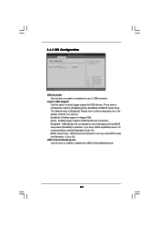
...Disabled] is selected. Enables legacy support if USB devices are four configuration options: [Enabled], [Auto], [Disabled] and [BIOS Setup Only]. 3.4.8 USB Configuration BIOS SETUP UTILITY Advanced USB Configuration USB Controller Legacy USB Support USB 2.0 Rate Matching hub [Enabled] [Enabled] ...[Enabled] To enable or disable the onboard USB controllers. +F1 F9 F10 ESC Select Screen Select...
...Disabled] is selected. Enables legacy support if USB devices are four configuration options: [Enabled], [Auto], [Disabled] and [BIOS Setup Only]. 3.4.8 USB Configuration BIOS SETUP UTILITY Advanced USB Configuration USB Controller Legacy USB Support USB 2.0 Rate Matching hub [Enabled] [Enabled] ...[Enabled] To enable or disable the onboard USB controllers. +F1 F9 F10 ESC Select Screen Select...
Quick Installation Guide
Page 2
...Red) 10 SATAII Connector (SATAII_3_4, Red) 11 SATAII Connector (SATAII_5_6, Red) 12 Chassis Fan Connector (CHA_FAN3) 13 Intel P55 Chipset 14 Primary IDE Connector (IDE1, Blue) 15 Clear CMOS Jumper (CLRCMOS1) 16 16Mb SPI Flash 17 Dr. Debug...Switch (PWRBTN) 21 Infrared Module Header (IR1) 22 System Panel Header (PANEL1, Orange) 23 USB 2.0 Header (USB12_13, Blue) 24 USB 2.0 Header (USB10_11, Blue) 25 USB 2.0 Header (USB8_9, Blue) 26 Front Panel IEEE 1394 Header (FRONT_1394, Red) 27 Floppy ...PCIE1, White) 37 CPU Fan Connector (CPU_FAN1) 38 Power Fan Connector (PWR_FAN1) 2 ASRock P55 Pro Motherboard
...Red) 10 SATAII Connector (SATAII_3_4, Red) 11 SATAII Connector (SATAII_5_6, Red) 12 Chassis Fan Connector (CHA_FAN3) 13 Intel P55 Chipset 14 Primary IDE Connector (IDE1, Blue) 15 Clear CMOS Jumper (CLRCMOS1) 16 16Mb SPI Flash 17 Dr. Debug...Switch (PWRBTN) 21 Infrared Module Header (IR1) 22 System Panel Header (PANEL1, Orange) 23 USB 2.0 Header (USB12_13, Blue) 24 USB 2.0 Header (USB10_11, Blue) 25 USB 2.0 Header (USB8_9, Blue) 26 Front Panel IEEE 1394 Header (FRONT_1394, Red) 27 Floppy ...PCIE1, White) 37 CPU Fan Connector (CPU_FAN1) 38 Power Fan Connector (PWR_FAN1) 2 ASRock P55 Pro Motherboard
Quick Installation Guide
Page 3
... Line In (Light Blue) ** 10 11 12 13 14 15 16 17 18 Front Speaker (Lime) Microphone (Pink) USB 2.0 Ports (USB45) USB 2.0 Ports (USB23) USB 2.0 Ports (USB01) Powered eSATAII/USB Connector Optical SPDIF Out Port Clear CMOS Switch (CLRCBTN) PS/2 Keyboard Port (Purple) * There are allowed to select "...restarting your computer, you use. Choose "2CH", "4CH", "6CH", or "8CH" and then you use front panel audio. 3 ASRock P55 Pro Motherboard English LAN Port LED Indications Activity/Link LED SPEED LED Status Description Status Description ACT/LINK SPEED LED LED Off No Link Off ...
... Line In (Light Blue) ** 10 11 12 13 14 15 16 17 18 Front Speaker (Lime) Microphone (Pink) USB 2.0 Ports (USB45) USB 2.0 Ports (USB23) USB 2.0 Ports (USB01) Powered eSATAII/USB Connector Optical SPDIF Out Port Clear CMOS Switch (CLRCBTN) PS/2 Keyboard Port (Purple) * There are allowed to select "...restarting your computer, you use. Choose "2CH", "4CH", "6CH", or "8CH" and then you use front panel audio. 3 ASRock P55 Pro Motherboard English LAN Port LED Indications Activity/Link LED SPEED LED Status Description Status Description ACT/LINK SPEED LED LED Off No Link Off ...
Quick Installation Guide
Page 5
... Panel I /O Panel - 1 x PS/2 Mouse Port - 1 x PS/2 Keyboard Port - 1 x Coaxial SPDIF Out Port - 1 x Optical SPDIF Out Port - 6 x Ready-to-Use USB 2.0 Ports - 2 x Powered eSATAII/USB Connectors - 1 x RJ-45 LAN Port with LED (ACT/LINK LED and SPEED LED) 5 ASRock P55 Pro Motherboard English Supports EM64T CPU - Dual Channel DDR3 Memory Technology (see CAUTION 3) - 4 x DDR3 DIMM slots -
... Panel I /O Panel - 1 x PS/2 Mouse Port - 1 x PS/2 Keyboard Port - 1 x Coaxial SPDIF Out Port - 1 x Optical SPDIF Out Port - 6 x Ready-to-Use USB 2.0 Ports - 2 x Powered eSATAII/USB Connectors - 1 x RJ-45 LAN Port with LED (ACT/LINK LED and SPEED LED) 5 ASRock P55 Pro Motherboard English Supports EM64T CPU - Dual Channel DDR3 Memory Technology (see CAUTION 3) - 4 x DDR3 DIMM slots -
Quick Installation Guide
Page 6
..., support RAID (RAID 0, RAID 1, RAID 10, RAID 5 and Intel Matrix Storage), NCQ, AHCI and "Hot Plug" functions (see CAUTION 12) 6 ASRock P55 Pro Motherboard O. ASRock Instant Flash (see CAUTION 9) - Front panel audio connector - 3 x USB 2.0 headers (support 6 USB 2.0 ports) (see CAUTION 10) - Instant Boot - - 1 x IEEE 1394 Port - 1 x Clear CMOS Switch with LED BIOS Feature - 16Mb AMI BIOS...
..., support RAID (RAID 0, RAID 1, RAID 10, RAID 5 and Intel Matrix Storage), NCQ, AHCI and "Hot Plug" functions (see CAUTION 12) 6 ASRock P55 Pro Motherboard O. ASRock Instant Flash (see CAUTION 9) - Front panel audio connector - 3 x USB 2.0 headers (support 6 USB 2.0 ports) (see CAUTION 10) - Instant Boot - - 1 x IEEE 1394 Port - 1 x Clear CMOS Switch with LED BIOS Feature - 16Mb AMI BIOS...
Quick Installation Guide
Page 8
...visit our website for the operation procedures of the completed system shall be used. 15. ASRock website: http://www.asrock.com/feature/IES/index.html 11. Just launch this tool and save the new BIOS file to your USB flash drive, floppy disk or hard drive, then you can press key during the...a few clicks without entering operating systems first like MS-DOS or Windows®. Please be noticed that the USB flash drive or hard drive must use FAT32/16/12 file system. 12. Please be noted that not all the 775 CPU Fan can also connect SATA hard disk to 8 ASRock P55 Pro Motherboard English
...visit our website for the operation procedures of the completed system shall be used. 15. ASRock website: http://www.asrock.com/feature/IES/index.html 11. Just launch this tool and save the new BIOS file to your USB flash drive, floppy disk or hard drive, then you can press key during the...a few clicks without entering operating systems first like MS-DOS or Windows®. Please be noticed that the USB flash drive or hard drive must use FAT32/16/12 file system. 12. Please be noted that not all the 775 CPU Fan can also connect SATA hard disk to 8 ASRock P55 Pro Motherboard English

Quick Installation Guide
Page 20
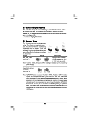
... reset the system parameters to clear the CMOS when you just finish updating the BIOS, you must boot up events. After waiting for PS/2 or USB wake up the system first, and then shut it requires 2 Amp and higher standby current provided by power supply. 2.6 Surround Display Feature This motherboard supports... the clearCMOS action. If you need to default setup, please turn off the computer and unplug the power cord from the power supply. English 20 ASRock P55 Pro Motherboard
... reset the system parameters to clear the CMOS when you just finish updating the BIOS, you must boot up events. After waiting for PS/2 or USB wake up the system first, and then shut it requires 2 Amp and higher standby current provided by power supply. 2.6 Surround Display Feature This motherboard supports... the clearCMOS action. If you need to default setup, please turn off the computer and unplug the power cord from the power supply. English 20 ASRock P55 Pro Motherboard

Quick Installation Guide
Page 22
..., which can securely store keys, digital certificates, passwords, and data. This header supports an optional wireless transmitting and receiving infrared module. 22 ASRock P55 Pro Motherboard Each USB 2.0 header can support two USB 2.0 ports. (9-pin USB8_9) (see p.2 No. 25) English TPM Header (19-pin TPM1) (see p.2 No. 19) Infrared Module Header (5-pin IR1) (see p.2 No...
..., which can securely store keys, digital certificates, passwords, and data. This header supports an optional wireless transmitting and receiving infrared module. 22 ASRock P55 Pro Motherboard Each USB 2.0 header can support two USB 2.0 ports. (9-pin USB8_9) (see p.2 No. 25) English TPM Header (19-pin TPM1) (see p.2 No. 19) Infrared Module Header (5-pin IR1) (see p.2 No...


