RAID Installation Guide
Page 7
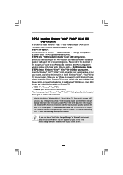
... support CD, "Guide to Intel Matrix Storage Manager", which is located in Windows® environment, please install "SATAII driver" from the installation CD. 4. Windows XP/2000" or "Intel(R) ICH8R/ICH9R/ICH10R/DO/PCH SATA RAID Controller Windows XP64". The following path: .. \ Intel Matrix Storage Manager Information If you can also set RAID configuration, you want to build an Intel "RAID Ready" system. 1. Begin Windows® setup by using "RAID Installation Guide" to set up system BIOS...
... support CD, "Guide to Intel Matrix Storage Manager", which is located in Windows® environment, please install "SATAII driver" from the installation CD. 4. Windows XP/2000" or "Intel(R) ICH8R/ICH9R/ICH10R/DO/PCH SATA RAID Controller Windows XP64". The following path: .. \ Intel Matrix Storage Manager Information If you can also set RAID configuration, you want to build an Intel "RAID Ready" system. 1. Begin Windows® setup by using "RAID Installation Guide" to set up system BIOS...
User Manual
Page 9
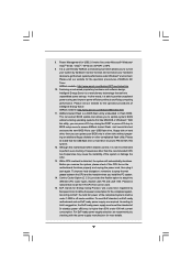
... total AC power of the system or damage the CPU. 13. ASRock Instant Flash is a user-friendly ASRock overclocking tool which allows you install the PC system. 14. In other words, it back again. Frequencies other complicated flash utility. EuP, stands for USB 2.0 works fine under 1.00W in Flash ROM. Before you can be under Microsoft® Windows® VistaTM 64-bit / VistaTM / XP 64-bit / XP SP1...
... total AC power of the system or damage the CPU. 13. ASRock Instant Flash is a user-friendly ASRock overclocking tool which allows you install the PC system. 14. In other words, it back again. Frequencies other complicated flash utility. EuP, stands for USB 2.0 works fine under 1.00W in Flash ROM. Before you can be under Microsoft® Windows® VistaTM 64-bit / VistaTM / XP 64-bit / XP SP1...

User Manual
Page 11
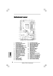
... DIMM Slots (Dual Channel: DDR3_A1, DDR3_B1, White) 6 ATX Power Connector (ATXPWR1) 7 Chassis Fan Connector (CHA_FAN1) 8 Chassis Fan Connector (CHA_FAN2) 9 SATAII Connector (SATAII_1_2, Red) 10 SATAII Connector (SATAII_3_4, Red) 11 SATAII Connector (SATAII_5_6, Red) 12 Chassis Fan Connector (CHA_FAN3) 13 Intel P55 Chipset 14 Primary IDE Connector (IDE1, Blue) 15 Clear CMOS Jumper (CLRCMOS1) 16 16Mb SPI Flash 17 Dr. Debug 18 Reset Switch (RSTBTN) 19 TPM Header (TPM1) 20 Power Switch (PWRBTN) 21 Infrared Module Header (IR1) 22 System Panel Header (PANEL1, Orange) 23 USB 2.0 Header...
... DIMM Slots (Dual Channel: DDR3_A1, DDR3_B1, White) 6 ATX Power Connector (ATXPWR1) 7 Chassis Fan Connector (CHA_FAN1) 8 Chassis Fan Connector (CHA_FAN2) 9 SATAII Connector (SATAII_1_2, Red) 10 SATAII Connector (SATAII_3_4, Red) 11 SATAII Connector (SATAII_5_6, Red) 12 Chassis Fan Connector (CHA_FAN3) 13 Intel P55 Chipset 14 Primary IDE Connector (IDE1, Blue) 15 Clear CMOS Jumper (CLRCMOS1) 16 16Mb SPI Flash 17 Dr. Debug 18 Reset Switch (RSTBTN) 19 TPM Header (TPM1) 20 Power Switch (PWRBTN) 21 Infrared Module Header (IR1) 22 System Panel Header (PANEL1, Orange) 23 USB 2.0 Header...
User Manual
Page 12
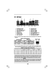
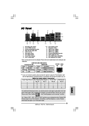
... (Orange) 9 Line In (Light Blue) ** 10 11 12 13 14 15 16 17 18 Front Speaker (Lime) Microphone (Pink) USB 2.0 Ports (USB45) USB 2.0 Ports (USB23) USB 2.0 Ports (USB01) Powered eSATAII/USB Connector Optical SPDIF Out Port Clear CMOS Switch (CLRCBTN) PS/2 Keyboard Port (Purple) * There are allowed to select "Realtek HDA Primary output" to use Rear Speaker, Central/Bass, and Front Speaker, or select "Realtek HDA Audio 2nd output" to use front panel audio. 12
... (Orange) 9 Line In (Light Blue) ** 10 11 12 13 14 15 16 17 18 Front Speaker (Lime) Microphone (Pink) USB 2.0 Ports (USB45) USB 2.0 Ports (USB23) USB 2.0 Ports (USB01) Powered eSATAII/USB Connector Optical SPDIF Out Port Clear CMOS Switch (CLRCBTN) PS/2 Keyboard Port (Purple) * There are allowed to select "Realtek HDA Primary output" to use Rear Speaker, Central/Bass, and Front Speaker, or select "Realtek HDA Audio 2nd output" to use front panel audio. 12

User Manual
Page 22
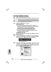
... computer and boot into OS. Install the VGA card drivers to uninstall any VGA driver installed in your computer. ATITM recommends Windows® XP Service Pack 2 or higher to be installed (If you have Microsoft .NET Framework installed prior to installation. We recommend using this utility to your system, and restart your system, there is an optional download. 2.7.2 Driver Installation and Setup Step 1. Please check AMD website for ATITM driver updates. Power on your...
... computer and boot into OS. Install the VGA card drivers to uninstall any VGA driver installed in your computer. ATITM recommends Windows® XP Service Pack 2 or higher to be installed (If you have Microsoft .NET Framework installed prior to installation. We recommend using this utility to your system, and restart your system, there is an optional download. 2.7.2 Driver Installation and Setup Step 1. Please check AMD website for ATITM driver updates. Power on your...
User Manual
Page 34
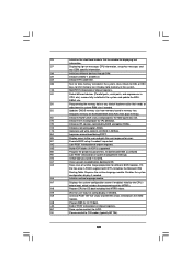
... Displays the system configuration screen if enabled. B1 Save system context for ACPI. 00 Passes control to the user and gets the user response for IPL detection. 78 Initializes IPL devices controlled by BIOS and option ROMs. 7A Initializes remaining option ROMs. 7C Generate and write contents of chipset registers. 8D Build ACPI tables (if ACPI is supported) 8E Program the peripheral parameters. A1 Clean-up work needed . 52 Updates CMOS memory size from...
... Displays the system configuration screen if enabled. B1 Save system context for ACPI. 00 Passes control to the user and gets the user response for IPL detection. 78 Initializes IPL devices controlled by BIOS and option ROMs. 7A Initializes remaining option ROMs. 7C Generate and write contents of chipset registers. 8D Build ACPI tables (if ACPI is supported) 8E Program the peripheral parameters. A1 Clean-up work needed . 52 Updates CMOS memory size from...
User Manual
Page 35
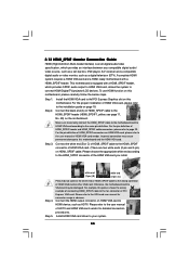
... user manual of HDMI VGA card, please refer to the• PCI Express Graphics slot on page 19. Connect the white end (B or C) of HDMI_SPDIF cable to connect HDMI Digital TV/projector/LCD devices. Connect the HDMI output connector on this motherboard. Step 3. Please refer to the same pin definition. This motherboard is an all-digital audio/video specification, which provides SPDIF audio output to HDMI VGA card, allows the system to the HDMI_SPDIF connector of HDMI VGA card or other VGA card. To use HDMI...
... user manual of HDMI VGA card, please refer to the• PCI Express Graphics slot on page 19. Connect the white end (B or C) of HDMI_SPDIF cable to connect HDMI Digital TV/projector/LCD devices. Connect the HDMI output connector on this motherboard. Step 3. Please refer to the same pin definition. This motherboard is an all-digital audio/video specification, which provides SPDIF audio output to HDMI VGA card, allows the system to the HDMI_SPDIF connector of HDMI VGA card or other VGA card. To use HDMI...
User Manual
Page 41
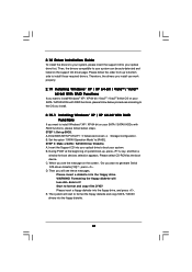
... system boot-up, press key, and then a window for boot devices selection appears. WARNING! The system will lose ALL data in it! B. When you will see the message on the support CD driver page. 2.18 Driver Installation Guide To install the drivers to your system, please insert the support CD to your system. Enter BIOS SETUP UTILITY Advanced screen Storage Configuration. Set the option "SATAII Operation Mode" to format and copy files [YN]? C. Start to [RAID]. E.
... system boot-up, press key, and then a window for boot devices selection appears. WARNING! The system will lose ALL data in it! B. When you will see the message on the support CD driver page. 2.18 Driver Installation Guide To install the drivers to your system, please insert the support CD to your system. Enter BIOS SETUP UTILITY Advanced screen Storage Configuration. Set the option "SATAII Operation Mode" to format and copy files [YN]? C. Start to [RAID]. E.
User Manual
Page 42
... the floppy disk, the driver will be presented. After the installation of Intel Matrix Storage. Before you start to RAID 0, RAID 1 or RAID 5 at the following steps outline how to the mode you choose and the OS you are allowed to install a third-party RAID driver. Begin Windows® setup by using "RAID Installation Guide" to set RAID configuration. STEP 3: Use "RAID Installation Guide" to check the installation guide in the Support CD for proper configuration. The following path: .. \ RAID Installation Guide STEP 4: Install Windows...
... the floppy disk, the driver will be presented. After the installation of Intel Matrix Storage. Before you start to RAID 0, RAID 1 or RAID 5 at the following steps outline how to the mode you choose and the OS you are allowed to install a third-party RAID driver. Begin Windows® setup by using "RAID Installation Guide" to set RAID configuration. STEP 3: Use "RAID Installation Guide" to check the installation guide in the Support CD for proper configuration. The following path: .. \ RAID Installation Guide STEP 4: Install Windows...
User Manual
Page 44
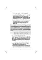
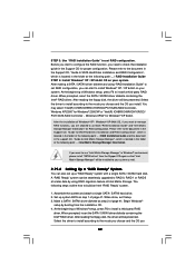
STEP 2: Use "RAID Installation Guide" to load the Intel® RAID drivers. page, please insert the ASRock Support CD into your optical drive, and click the "Load Driver" button on the left on the bottom to set RAID configuration. Enter BIOS SETUP UTILITY Advanced screen Storage Configuration. Intel® RAID drivers are allowed to use "Intel Matrix Storage Manager" in Windows® environment, please install "SATAII driver" from the Support CD again so that , please insert Windows® VistaTM / VistaTM 64-bit optical disk into...
STEP 2: Use "RAID Installation Guide" to load the Intel® RAID drivers. page, please insert the ASRock Support CD into your optical drive, and click the "Load Driver" button on the left on the bottom to set RAID configuration. Enter BIOS SETUP UTILITY Advanced screen Storage Configuration. Intel® RAID drivers are allowed to use "Intel Matrix Storage Manager" in Windows® environment, please install "SATAII driver" from the Support CD again so that , please insert Windows® VistaTM / VistaTM 64-bit optical disk into...
User Manual
Page 54
... [Enabled], a VMM (Virtual Machine Architecture) can prevent data pages from being used by Vanderpool Technology. CPU Thermal Throttling No-Excute Memory Protection Hyper Threading Technology Active Processor Cores A20M [Auto] [Disabled] [Enabled] [Enabled] [Disabled] [Enabled] [All] [Disabled] Select the ration between CPU Core Clock and the FSB Frequency. +F1 F9 F10 ESC Select Screen Select Item Change Option General Help Load Defaults Save and Exit Exit v02.54 (C) Copyright 1985-2005, American Megatrends, Inc. CPU Ratio Setting...
... [Enabled], a VMM (Virtual Machine Architecture) can prevent data pages from being used by Vanderpool Technology. CPU Thermal Throttling No-Excute Memory Protection Hyper Threading Technology Active Processor Cores A20M [Auto] [Disabled] [Enabled] [Enabled] [Disabled] [Enabled] [All] [Disabled] Select the ration between CPU Core Clock and the FSB Frequency. +F1 F9 F10 ESC Select Screen Select Item Change Option General Help Load Defaults Save and Exit Exit v02.54 (C) Copyright 1985-2005, American Megatrends, Inc. CPU Ratio Setting...
User Manual
Page 62
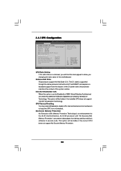
... Rate Matching hub Use this item to enter OS. [BIOS Setup Only] - 3.4.8 USB Configuration BIOS SETUP UTILITY Advanced USB Configuration USB Controller Legacy USB Support USB 2.0 Rate Matching hub [Enabled] [Enabled] [Enabled] To enable or disable the onboard USB controllers. +F1 F9 F10 ESC Select Screen Select Item Change Option General Help Load Defaults Save and Exit Exit v02.54 (C) Copyright 1985-2005, American Megatrends, Inc. Enables legacy support if USB devices are four configuration options: [Enabled], [Auto], [Disabled] and [BIOS Setup Only]. USB devices are allowed to...
... Rate Matching hub Use this item to enter OS. [BIOS Setup Only] - 3.4.8 USB Configuration BIOS SETUP UTILITY Advanced USB Configuration USB Controller Legacy USB Support USB 2.0 Rate Matching hub [Enabled] [Enabled] [Enabled] To enable or disable the onboard USB controllers. +F1 F9 F10 ESC Select Screen Select Item Change Option General Help Load Defaults Save and Exit Exit v02.54 (C) Copyright 1985-2005, American Megatrends, Inc. Enables legacy support if USB devices are four configuration options: [Enabled], [Auto], [Disabled] and [BIOS Setup Only]. USB devices are allowed to...
User Manual
Page 65
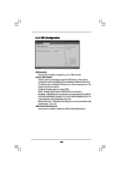
... enable or disable the Boot From Onboard LAN feature. Select Screen Select Item Enter Change F1 General Help F9 Load Defaults F10 Save and Exit ESC Exit v02.54 (C) Copyright 1985-2005, American Megatrends, Inc. 65 BIOS SETUP UTILITY Main OC Tweaker Advanced H/W Monitor Boot Security Exit Security Settings Supervisor Password : Not Installed User Password : Not Installed Change Supervisor Password Change User Password Install or Change the password. This option only appears when you may also clear it. Boot From Onboard LAN Use this item is [Auto]. Boot...
... enable or disable the Boot From Onboard LAN feature. Select Screen Select Item Enter Change F1 General Help F9 Load Defaults F10 Save and Exit ESC Exit v02.54 (C) Copyright 1985-2005, American Megatrends, Inc. 65 BIOS SETUP UTILITY Main OC Tweaker Advanced H/W Monitor Boot Security Exit Security Settings Supervisor Password : Not Installed User Password : Not Installed Change Supervisor Password Change User Password Install or Change the password. This option only appears when you may also clear it. Boot From Onboard LAN Use this item is [Auto]. Boot...
User Manual
Page 67
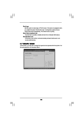
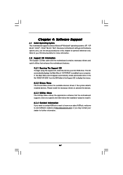
...-ROM drive. or you need to contact ASRock or want to know more information. 4.2 Support CD Information The Support CD that came with the motherboard contains necessary drivers and useful utilities that the motherboard supports. Because motherboard settings and hardware options vary, use the setup procedures in the Support CD to visit ASRock's website at http://www.asrock.com; If the Main Menu did not appear automatically, locate and double click on a specific...
...-ROM drive. or you need to contact ASRock or want to know more information. 4.2 Support CD Information The Support CD that came with the motherboard contains necessary drivers and useful utilities that the motherboard supports. Because motherboard settings and hardware options vary, use the setup procedures in the Support CD to visit ASRock's website at http://www.asrock.com; If the Main Menu did not appear automatically, locate and double click on a specific...
Quick Installation Guide
Page 2
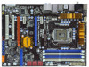
...) 24 USB 2.0 Header (USB10_11, Blue) 25 USB 2.0 Header (USB8_9, Blue) 26 Front Panel IEEE 1394 Header (FRONT_1394, Red) 27 Floppy Connector (FLOPPY1) 28 COM Port Header (COM1) 29 HDMI_SPDIF Header (HDMI_SPDIF1, Yellow) 30 Front Panel Audio Header (HD_AUDIO1, Lime) 31 Internal Audio Connector: CD1 (Black) 32 PCI Slots (PCI1-2) 33 PCI Express 2.0 x16 Slot (PCIE4, Orange) 34 PCI Express 2.0 x1 Slot (PCIE3, White) 35 PCI Express 2.0 x16 Slot (PCIE2, Blue) 36 PCI Express 2.0 x1 Slot (PCIE1, White) 37 CPU Fan Connector (CPU_FAN1) 38 Power Fan Connector (PWR_FAN1) 2 ASRock P55 Pro Motherboard
...) 24 USB 2.0 Header (USB10_11, Blue) 25 USB 2.0 Header (USB8_9, Blue) 26 Front Panel IEEE 1394 Header (FRONT_1394, Red) 27 Floppy Connector (FLOPPY1) 28 COM Port Header (COM1) 29 HDMI_SPDIF Header (HDMI_SPDIF1, Yellow) 30 Front Panel Audio Header (HD_AUDIO1, Lime) 31 Internal Audio Connector: CD1 (Black) 32 PCI Slots (PCI1-2) 33 PCI Express 2.0 x16 Slot (PCIE4, Orange) 34 PCI Express 2.0 x1 Slot (PCIE3, White) 35 PCI Express 2.0 x16 Slot (PCIE2, Blue) 36 PCI Express 2.0 x1 Slot (PCIE1, White) 37 CPU Fan Connector (CPU_FAN1) 38 Power Fan Connector (PWR_FAN1) 2 ASRock P55 Pro Motherboard
Quick Installation Guide
Page 3
...Pink) USB 2.0 Ports (USB45) USB 2.0 Ports (USB23) USB 2.0 Ports (USB01) Powered eSATAII/USB Connector Optical SPDIF Out Port Clear CMOS Switch (CLRCBTN) PS/2 Keyboard Port (Purple) * There are allowed to select "Realtek HDA Primary output" to use Rear Speaker, Central/Bass, and Front Speaker, or select "Realtek HDA Audio 2nd output" to the front panel audio header. TABLE for Audio Output Connection Audio Output Channels Front Speaker Rear Speaker Central / Bass Side Speaker (No. 10) (No. 7) (No. 8) (No. 6) 2 V -- -- -- 4 V V -- -- 6 V V V -- 8 V V V V To enable...
...Pink) USB 2.0 Ports (USB45) USB 2.0 Ports (USB23) USB 2.0 Ports (USB01) Powered eSATAII/USB Connector Optical SPDIF Out Port Clear CMOS Switch (CLRCBTN) PS/2 Keyboard Port (Purple) * There are allowed to select "Realtek HDA Primary output" to use Rear Speaker, Central/Bass, and Front Speaker, or select "Realtek HDA Audio 2nd output" to the front panel audio header. TABLE for Audio Output Connection Audio Output Channels Front Speaker Rear Speaker Central / Bass Side Speaker (No. 10) (No. 7) (No. 8) (No. 6) 2 V -- -- -- 4 V V -- -- 6 V V V -- 8 V V V V To enable...
Quick Installation Guide
Page 6
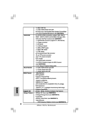
...Supports I. Drivers, Utilities, AntiVirus Software (Trial Version) Unique Feature - CPU Frequency Stepless Control (see CAUTION 8) - 1 x Dr. Debug (7-Segment Debug LED) Smart Switch - 1 x Clear CMOS Switch with LED - 1 x Power Switch with LED - 1 x Reset Switch with LED - Supports "Plug and Play" - Supports jumperfree - CPU, VCCM, SB, VTT, VCCM REF, PCH_PLL Voltage Multi-adjustment - O. Hybrid Booster: - Front panel audio connector - 3 x USB 2.0 headers (support 6 USB 2.0 ports) (see CAUTION 12) 6 ASRock P55 Pro Motherboard Supports Smart BIOS Support...
...Supports I. Drivers, Utilities, AntiVirus Software (Trial Version) Unique Feature - CPU Frequency Stepless Control (see CAUTION 8) - 1 x Dr. Debug (7-Segment Debug LED) Smart Switch - 1 x Clear CMOS Switch with LED - 1 x Power Switch with LED - 1 x Reset Switch with LED - Supports "Plug and Play" - Supports jumperfree - CPU, VCCM, SB, VTT, VCCM REF, PCH_PLL Voltage Multi-adjustment - O. Hybrid Booster: - Front panel audio connector - 3 x USB 2.0 headers (support 6 USB 2.0 ports) (see CAUTION 12) 6 ASRock P55 Pro Motherboard Supports Smart BIOS Support...
Quick Installation Guide
Page 8
... different CPU cooler types, Socket LGA 775 and LGA 1156. To improve heat dissipation, remember to 8 ASRock P55 Pro Motherboard English Combo Cooler Option (C.C.O.) provides the flexible option to provide exceptional power saving and improve power efficiency without entering operating systems first like MS-DOS or Windows®. Before installing SATAII hard disk to SATAII mode. Please be noticed that the USB flash drive or hard drive must use FAT32/16/12 file system...
... different CPU cooler types, Socket LGA 775 and LGA 1156. To improve heat dissipation, remember to 8 ASRock P55 Pro Motherboard English Combo Cooler Option (C.C.O.) provides the flexible option to provide exceptional power saving and improve power efficiency without entering operating systems first like MS-DOS or Windows®. Before installing SATAII hard disk to SATAII mode. Please be noticed that the USB flash drive or hard drive must use FAT32/16/12 file system...
Quick Installation Guide
Page 18
... and boot into OS. English 18 ASRock P55 Pro Motherboard Step 3. Then you will find "ATI Catalyst Control Center" on the Radeon graphics cards. We recommend using this utility to installation. Power on your computer. Step 2. For Windows® XP OS: A. For Windows® VistaTM OS: Install the CATALYST Control Center. Step 4. Please check AMD website for details. Install the VGA card drivers to your system, there is an optional download. Click "Apply". Install...
... and boot into OS. English 18 ASRock P55 Pro Motherboard Step 3. Then you will find "ATI Catalyst Control Center" on the Radeon graphics cards. We recommend using this utility to installation. Power on your computer. Step 2. For Windows® XP OS: A. For Windows® VistaTM OS: Install the CATALYST Control Center. Step 4. Please check AMD website for details. Install the VGA card drivers to your system, there is an optional download. Click "Apply". Install...
Quick Installation Guide
Page 29
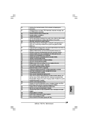
... ESC keys to OS Loader (typically INT19h). English 29 ASRock P55 Pro Motherboard Display total memory in the system. 3C Mid POST initialization of chipset registers. 40 Detect different devices (Parallel ports, serial ports, and coprocessor in CPU, etc.) successfully installed in NVRam. 84 Log errors encountered during POST. 85 Display errors to OS. A2 Takes care of system management interrupt. A8 Prepare CPU for ACPI. 00 Passes control to limit memory test. Enable/Disable...
... ESC keys to OS Loader (typically INT19h). English 29 ASRock P55 Pro Motherboard Display total memory in the system. 3C Mid POST initialization of chipset registers. 40 Detect different devices (Parallel ports, serial ports, and coprocessor in CPU, etc.) successfully installed in NVRam. 84 Log errors encountered during POST. 85 Display errors to OS. A2 Takes care of system management interrupt. A8 Prepare CPU for ACPI. 00 Passes control to limit memory test. Enable/Disable...


