
RAID Installation Guide
Page 2
...hard disks on SATA ports. 2 For SATA installation guide, please refer to SATA Hard Disks Installation 1.1 Serial ATA (SATA) Hard Disks Installation Intel P55 chipset supports Serial ATA (SATA) hard disks with RAID functions, including RAID 0, RAID 1, RAID 10, RAID 5, and Intel Rapid Storage. Guide ...to Serial ATA (SATA) Hard Disks Installation of "User Manual" in this guide carefully according to create RAID on this motherboard for internal storage devices. Please read the RAID configurations in the support CD. 1. This section will guide you how to the Intel southbridge...
...hard disks on SATA ports. 2 For SATA installation guide, please refer to SATA Hard Disks Installation 1.1 Serial ATA (SATA) Hard Disks Installation Intel P55 chipset supports Serial ATA (SATA) hard disks with RAID functions, including RAID 0, RAID 1, RAID 10, RAID 5, and Intel Rapid Storage. Guide ...to Serial ATA (SATA) Hard Disks Installation of "User Manual" in this guide carefully according to create RAID on this motherboard for internal storage devices. Please read the RAID configurations in the support CD. 1. This section will guide you how to the Intel southbridge...

User Manual
Page 5
... CPU support lists on ASRock website without notice. www.asrock.com/support/index.asp 1.1 Package Contents ASRock P55 Deluxe3 Motherboard (ATX Form Factor: 12.0-in x 9.6-in, 30.5 cm x 24.4 cm) ASRock P55 Deluxe3 Quick Installation Guide ASRock P55 Deluxe3 Support CD 1 x 80-conductor Ultra ATA 66/100/133 IDE Ribbon Cable 1 x Ribbon Cable for purchasing ASRock P55 Deluxe3 motherboard, a reliable motherboard produced under ASRock's consistently stringent quality control...
... CPU support lists on ASRock website without notice. www.asrock.com/support/index.asp 1.1 Package Contents ASRock P55 Deluxe3 Motherboard (ATX Form Factor: 12.0-in x 9.6-in, 30.5 cm x 24.4 cm) ASRock P55 Deluxe3 Quick Installation Guide ASRock P55 Deluxe3 Support CD 1 x 80-conductor Ultra ATA 66/100/133 IDE Ribbon Cable 1 x Ribbon Cable for purchasing ASRock P55 Deluxe3 motherboard, a reliable motherboard produced under ASRock's consistently stringent quality control...
User Manual
Page 12
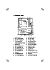
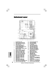
Clr CMOS 1.5 Motherboard Layout 12 3 24.4cm (9.6 in) PS2 Mouse PS2 Keyboard 1 PS2_USB_PWR1...39 38 PCIE1 LAN PHY PCIE2 CHA_FAN3 CHA_FAN2 IDE1 EuP Ready SATA3 6Gb/s SATAII_5_6 SATAII_3_4 SATAII_1_2 PCIE3 Super I/O P55 Deluxe3 Intel P55 PCIE4 PCI Express 2.0 1394a AUDIO CODEC HD_AUDIO1 1 CD1 HDMI_SPDIF1 1 FLOPPY1 PCI1 RoHS PCI2 COM1 1 CMOS ...19 16Mb SPI Flash 42 PCI Express 2.0 x1 Slot (PCIE3, White) 20 SATAII Connector (SATAII_5, Blue ) 43 Intel P55 Chipset 21 SATAII Connector (SATAII_6, Blue ) 44 PCI Express 2.0 x16 Slot (PCIE2, Blue) 22 Chassis Speaker Header (...
Clr CMOS 1.5 Motherboard Layout 12 3 24.4cm (9.6 in) PS2 Mouse PS2 Keyboard 1 PS2_USB_PWR1...39 38 PCIE1 LAN PHY PCIE2 CHA_FAN3 CHA_FAN2 IDE1 EuP Ready SATA3 6Gb/s SATAII_5_6 SATAII_3_4 SATAII_1_2 PCIE3 Super I/O P55 Deluxe3 Intel P55 PCIE4 PCI Express 2.0 1394a AUDIO CODEC HD_AUDIO1 1 CD1 HDMI_SPDIF1 1 FLOPPY1 PCI1 RoHS PCI2 COM1 1 CMOS ...19 16Mb SPI Flash 42 PCI Express 2.0 x1 Slot (PCIE3, White) 20 SATAII Connector (SATAII_5, Blue ) 43 Intel P55 Chipset 21 SATAII Connector (SATAII_6, Blue ) 44 PCI Express 2.0 x16 Slot (PCIE2, Blue) 22 Chassis Speaker Header (...
User Manual
Page 42
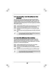
...SATA power cable to install the SATA / SATAII hard disks. 2.15 Serial ATA (SATA) / Serial ATAII (SATAII) Hard Disks Installation This motherboard adopts Intel® P55 chipset that supports Serial ATA3 (SATA3) hard disks and RAID (RAID 0 and RAID 1) functions. This section will guide you to the SATA3... hard disk. STEP 1: Install the SATA3 hard disks into the drive bays of the SATA data cable to the motherboard's SATAII connector....
...SATA power cable to install the SATA / SATAII hard disks. 2.15 Serial ATA (SATA) / Serial ATAII (SATAII) Hard Disks Installation This motherboard adopts Intel® P55 chipset that supports Serial ATA3 (SATA3) hard disks and RAID (RAID 0 and RAID 1) functions. This section will guide you to the SATA3... hard disk. STEP 1: Install the SATA3 hard disks into the drive bays of the SATA data cable to the motherboard's SATAII connector....
User Manual
Page 43
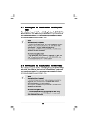
... SATA / SATAII HDDs while the system is still power-on and in working condition. 2.18 Hot Plug and Hot Swap Functions for SATA3 HDDs This motherboard supports Hot Plug and Hot Swap functions for SATA / SATAII in RAID / AHCI mode. 2.17 Hot Plug and Hot Swap Functions for SATA / ...are built as RAID1 or RAID 5 then it is still power-on and in working condition. 43 What is Hot Plug Function? Intel® P55 chipset provides hardware support for Advanced Host controller Interface (AHCI), a new programming interface for SATA host controllers developed thru a joint industry effort.
... SATA / SATAII HDDs while the system is still power-on and in working condition. 2.18 Hot Plug and Hot Swap Functions for SATA3 HDDs This motherboard supports Hot Plug and Hot Swap functions for SATA / SATAII in RAID / AHCI mode. 2.17 Hot Plug and Hot Swap Functions for SATA / ...are built as RAID1 or RAID 5 then it is still power-on and in working condition. 43 What is Hot Plug Function? Intel® P55 chipset provides hardware support for Advanced Host controller Interface (AHCI), a new programming interface for SATA host controllers developed thru a joint industry effort.

Quick Installation Guide
Page 1
..., without written consent of such damages arising from any defect or error in the guide or product. All rights reserved. 1 ASRock P55 Deluxe3 Motherboard English Copyright Notice: No part of this installation guide may be reproduced, transcribed, transmitted, or translated in any language, in any... for any indirect, special, incidental, or consequential damages (including damages for any errors or omissions that may appear in this motherboard contains Perchlorate, a toxic substance controlled in this guide may or may cause undesired operation. Products and corporate names appearing in ...
..., without written consent of such damages arising from any defect or error in the guide or product. All rights reserved. 1 ASRock P55 Deluxe3 Motherboard English Copyright Notice: No part of this installation guide may be reproduced, transcribed, transmitted, or translated in any language, in any... for any indirect, special, incidental, or consequential damages (including damages for any errors or omissions that may appear in this motherboard contains Perchlorate, a toxic substance controlled in this guide may or may cause undesired operation. Products and corporate names appearing in ...
Quick Installation Guide
Page 2
Motherboard Layout English 1 PS2_USB_PWR1 Jumper 24 Chassis Intrusion Header (CI1) 2 Power Fan Connector (PWR_FAN1) 25 Reset Switch (RSTBTN) 3 ATX 12V Power Connector (ATX12V1) 26 Power Switch (... PCI Express 2.0 x1 Slot (PCIE3, White) 20 SATAII Connector (SATAII_5, Blue ) 43 Intel P55 Chipset 21 SATAII Connector (SATAII_6, Blue ) 44 PCI Express 2.0 x16 Slot (PCIE2, Blue) 22 Chassis Speaker Header (SPEAKER 1, White) 45 PCI Express 2.0 x1 Slot (PCIE1, White) 23 System Panel Header (PANEL1, White) 46 Chassis Fan Connector (CHA_FAN2) 2 ASRock P55 Deluxe3 Motherboard
Motherboard Layout English 1 PS2_USB_PWR1 Jumper 24 Chassis Intrusion Header (CI1) 2 Power Fan Connector (PWR_FAN1) 25 Reset Switch (RSTBTN) 3 ATX 12V Power Connector (ATX12V1) 26 Power Switch (... PCI Express 2.0 x1 Slot (PCIE3, White) 20 SATAII Connector (SATAII_5, Blue ) 43 Intel P55 Chipset 21 SATAII Connector (SATAII_6, Blue ) 44 PCI Express 2.0 x16 Slot (PCIE2, Blue) 22 Chassis Speaker Header (SPEAKER 1, White) 45 PCI Express 2.0 x1 Slot (PCIE1, White) 23 System Panel Header (PANEL1, White) 46 Chassis Fan Connector (CHA_FAN2) 2 ASRock P55 Deluxe3 Motherboard

Quick Installation Guide
Page 3
... into "Front Speaker Jack". TABLE for Audio Output Connection Audio Output Channels Front Speaker Rear Speaker Central / Bass Side Speaker (No. 10) (No. 7) (No. 8) (No. 6) 2 V -- -- -- 4 V V -- -- 6 V V V -- 8 V V V V 3 ASRock P55 Deluxe3 Motherboard English I/O Panel 1 PS/2 Mouse Port (Green) 2 Coaxial SPDIF Out Port 3 USB 2.0 Port (USB12) 4 IEEE 1394 Port (IEEE 1394) * 5 LAN RJ-45 Port 6 Side Speaker (Gray...
... into "Front Speaker Jack". TABLE for Audio Output Connection Audio Output Channels Front Speaker Rear Speaker Central / Bass Side Speaker (No. 10) (No. 7) (No. 8) (No. 6) 2 V -- -- -- 4 V V -- -- 6 V V V -- 8 V V V V 3 ASRock P55 Deluxe3 Motherboard English I/O Panel 1 PS/2 Mouse Port (Green) 2 Coaxial SPDIF Out Port 3 USB 2.0 Port (USB12) 4 IEEE 1394 Port (IEEE 1394) * 5 LAN RJ-45 Port 6 Side Speaker (Gray...

Quick Installation Guide
Page 4
... HD Audio Deck" icon. Please follow below instructions according to the front panel audio header. In "Advanced Options" screen, please check the item "Independent Headphone". 4 ASRock P55 Deluxe3 Motherboard English Click "Jack" and then click "Configuration". For Windows® 7 / 7 64-bit / VistaTM / VistaTM 64-bit OS: Please click "VIA HD Audio Deck" icon. After...
... HD Audio Deck" icon. Please follow below instructions according to the front panel audio header. In "Advanced Options" screen, please check the item "Independent Headphone". 4 ASRock P55 Deluxe3 Motherboard English Click "Jack" and then click "Configuration". For Windows® 7 / 7 64-bit / VistaTM / VistaTM 64-bit OS: Please click "VIA HD Audio Deck" icon. After...

Quick Installation Guide
Page 5
... (SATA) HDD Power Cables (Optional) 1 x I/O Panel Shield 1 x ASRock SLI_Bridge_2S Card 5 ASRock P55 Deluxe3 Motherboard English In case any modifications of the motherboard and step-by-step installation guide. www.asrock.com/support/index.asp 1.1 Package Contents ASRock P55 Deluxe3 Motherboard (ATX Form Factor: 12.0-in x 9.6-in, 30.5 cm x 24.4 cm) ASRock P55 Deluxe3 Quick Installation Guide ASRock P55 Deluxe3 Support CD 1 x 80-conductor Ultra ATA 66/100...
... (SATA) HDD Power Cables (Optional) 1 x I/O Panel Shield 1 x ASRock SLI_Bridge_2S Card 5 ASRock P55 Deluxe3 Motherboard English In case any modifications of the motherboard and step-by-step installation guide. www.asrock.com/support/index.asp 1.1 Package Contents ASRock P55 Deluxe3 Motherboard (ATX Form Factor: 12.0-in x 9.6-in, 30.5 cm x 24.4 cm) ASRock P55 Deluxe3 Quick Installation Guide ASRock P55 Deluxe3 Support CD 1 x 80-conductor Ultra ATA 66/100...

Quick Installation Guide
Page 6
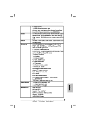
... DDR3 2600+(OC)/2133(OC)/1866(OC)/1600/ 1333/1066 non-ECC, un-buffered memory - DAC with LED (ACT/LINK LED and SPEED LED) ASRock P55 Deluxe3 Motherboard English 1.2 Specifications Platform CPU Chipset Memory Expansion Slot Audio LAN Rear Panel I /O Panel - 1 x PS/2 Mouse Port - 1 x PS/2 ... 2 x Ready-to-Use USB 3.0 Ports - 1 x RJ-45 LAN Port with 110dB dynamic range (VIA® VT2020 Audio Codec) - Intel® P55 - Max. Supports ATITM CrossFireXTM and Quad CrossFireXTM - Premium Blu-ray audio support - capacity of system memory: 16GB (see CAUTION 3) - 4 x DDR3 DIMM ...
... DDR3 2600+(OC)/2133(OC)/1866(OC)/1600/ 1333/1066 non-ECC, un-buffered memory - DAC with LED (ACT/LINK LED and SPEED LED) ASRock P55 Deluxe3 Motherboard English 1.2 Specifications Platform CPU Chipset Memory Expansion Slot Audio LAN Rear Panel I /O Panel - 1 x PS/2 Mouse Port - 1 x PS/2 ... 2 x Ready-to-Use USB 3.0 Ports - 1 x RJ-45 LAN Port with 110dB dynamic range (VIA® VT2020 Audio Codec) - Intel® P55 - Max. Supports ATITM CrossFireXTM and Quad CrossFireXTM - Premium Blu-ray audio support - capacity of system memory: 16GB (see CAUTION 3) - 4 x DDR3 DIMM ...
Quick Installation Guide
Page 7
... - 1 x COM port header - 1 x HDMI_SPDIF header - 1 x IEEE 1394 header - 1 x TPM header - 1 x Chassis Intrusion header - 1 x Power LED header - ACPI 1.1 Compliance Wake Up Events - Supports jumperfree - SMBIOS 2.3.1 Support 7 ASRock P55 Deluxe3 Motherboard English CPU/Chassis/Power FAN connector - 24 pin ATX power connector - 8 pin 12V power connector - SATA3 USB3.0 Connector Smart Switch BIOS Feature - 1 x IEEE 1394 Port...
... - 1 x COM port header - 1 x HDMI_SPDIF header - 1 x IEEE 1394 header - 1 x TPM header - 1 x Chassis Intrusion header - 1 x Power LED header - ACPI 1.1 Compliance Wake Up Events - Supports jumperfree - SMBIOS 2.3.1 Support 7 ASRock P55 Deluxe3 Motherboard English CPU/Chassis/Power FAN connector - 24 pin ATX power connector - 8 pin 12V power connector - SATA3 USB3.0 Connector Smart Switch BIOS Feature - 1 x IEEE 1394 Port...

Quick Installation Guide
Page 8
...X-Fi MB) (OEM and Trial Version) Unique Feature - Instant Boot - ASRock OC DNA (see CAUTION 13) - ASRock U-COP (see CAUTION 11) - Good Night LED Hardware - Chassis Temperature ...asrock.com WARNING Please realize that there is a certain risk involved with overclocking, including adjusting the setting in the BIOS, applying Untied Overclocking Technology, or using the thirdparty overclocking tools. - Supports I. ASRock Instant Flash (see CAUTION 14) - CPU Temperature Sensing Monitor - Combo Cooler Option (C.C.O.) (see CAUTION 10) - English 8 ASRock P55 Deluxe3 Motherboard...
...X-Fi MB) (OEM and Trial Version) Unique Feature - Instant Boot - ASRock OC DNA (see CAUTION 13) - ASRock U-COP (see CAUTION 11) - Good Night LED Hardware - Chassis Temperature ...asrock.com WARNING Please realize that there is a certain risk involved with overclocking, including adjusting the setting in the BIOS, applying Untied Overclocking Technology, or using the thirdparty overclocking tools. - Supports I. ASRock Instant Flash (see CAUTION 14) - CPU Temperature Sensing Monitor - Combo Cooler Option (C.C.O.) (see CAUTION 10) - English 8 ASRock P55 Deluxe3 Motherboard...
Quick Installation Guide
Page 9
... that the USB flash drive or hard drive must use FAT32/16/12 file system. 9 ASRock P55 Deluxe3 Motherboard English For audio output, this motherboard supports both stereo and mono modes. Please visit our website for the operation procedures of ASRock OC Tuner. Please be less than 4GB for the reservation for proper connection. 7. In other...
... that the USB flash drive or hard drive must use FAT32/16/12 file system. 9 ASRock P55 Deluxe3 Motherboard English For audio output, this motherboard supports both stereo and mono modes. Please visit our website for the operation procedures of ASRock OC Tuner. Please be less than 4GB for the reservation for proper connection. 7. In other...

Quick Installation Guide
Page 10
...It helps you checking with others. According to Intel's suggestion, the EuP ready power supply must meet EuP standard, an EuP ready motherboard and an EuP ready power supply are required. To meet the standard of the system or damage the CPU. 13. Before you can... shutdown. To improve heat dissipation, remember to record the OC settings and share with the power supply manufacturer for more details. 10 ASRock P55 Deluxe3 Motherboard English Combo Cooler Option (C.C.O.) provides the flexible option to save your OC settings as yours! For EuP ready power supply selection, we...
...It helps you checking with others. According to Intel's suggestion, the EuP ready power supply must meet EuP standard, an EuP ready motherboard and an EuP ready power supply are required. To meet the standard of the system or damage the CPU. 13. Before you can... shutdown. To improve heat dissipation, remember to record the OC settings and share with the power supply manufacturer for more details. 10 ASRock P55 Deluxe3 Motherboard English Combo Cooler Option (C.C.O.) provides the flexible option to save your OC settings as yours! For EuP ready power supply selection, we...

Quick Installation Guide
Page 11
ASRock website: http://www.asrock.com/support/index.htm 1.4 Two CrossFireXTM Graphics Card Support List (for Windows® XP / XP 64-bit / VistaTM / VistaTM 64-bit / 7 / 7 64-bit) Chipset Vendor ... * For the latest updates of the supported PCI Express VGA card list for SLITM Mode, please visit our website for details. ASRock website: http://www.asrock.com/support/index.htm English 11 ASRock P55 Deluxe3 Motherboard 1.3 Two SLITM Graphics Card Support List (for Windows® XP / XP 64-bit / VistaTM / VistaTM 64-bit / 7 / 7 64-bit) Chipset...
ASRock website: http://www.asrock.com/support/index.htm 1.4 Two CrossFireXTM Graphics Card Support List (for Windows® XP / XP 64-bit / VistaTM / VistaTM 64-bit / 7 / 7 64-bit) Chipset Vendor ... * For the latest updates of the supported PCI Express VGA card list for SLITM Mode, please visit our website for details. ASRock website: http://www.asrock.com/support/index.htm English 11 ASRock P55 Deluxe3 Motherboard 1.3 Two SLITM Graphics Card Support List (for Windows® XP / XP 64-bit / VistaTM / VistaTM 64-bit / 7 / 7 64-bit) Chipset...

Quick Installation Guide
Page 12
... you handle components. 3. Hold components by the edges and do so may damage the motherboard. 2.1 CPU Installation For the installation of the following precautions before you uninstall any motherboard settings. 1. When placing screws into the socket if above situation is any component. Do...please check if the CPU surface is unclean or if there is found. 2. Otherwise, the CPU will be seriously damaged. 12 ASRock P55 Deluxe3 Motherboard English Doing so may cause severe damage to use a grounded wrist strap or touch a safety grounded object before touching any bent ...
... you handle components. 3. Hold components by the edges and do so may damage the motherboard. 2.1 CPU Installation For the installation of the following precautions before you uninstall any motherboard settings. 1. When placing screws into the socket if above situation is any component. Do...please check if the CPU surface is unclean or if there is found. 2. Otherwise, the CPU will be seriously damaged. 12 ASRock P55 Deluxe3 Motherboard English Doing so may cause severe damage to use a grounded wrist strap or touch a safety grounded object before touching any bent ...

Quick Installation Guide
Page 13
...) up. Locate Pin1 and the two orientation key notches. Rotate the load lever to match the two orientation key notches of the socket. Step 2. Step 3. ASRock P55 Deluxe3 Motherboard Pin1 13 English Step 1-3. black line Step 3-2. Open the socket: Step 1-1. This cap must be placed if returning the... motherboard for after service. Hold the CPU by depressing down and out on the hook to handle and avoid kicking off the PnP cap. 2. It is ...
...) up. Locate Pin1 and the two orientation key notches. Rotate the load lever to match the two orientation key notches of the socket. Step 2. Step 3. ASRock P55 Deluxe3 Motherboard Pin1 13 English Step 1-3. black line Step 3-2. Open the socket: Step 1-1. This cap must be placed if returning the... motherboard for after service. Hold the CPU by depressing down and out on the hook to handle and avoid kicking off the PnP cap. 2. It is ...

Quick Installation Guide
Page 14
...is an example to the CPU fan connector on load plate, engage the load lever. Repeat with the motherboard throughholes. If you press down on the motherboard. While pressing down lightly on the motherboard (CPU_FAN1, see page 2, No. 5). Below is within the socket and properly mated to install and ... The white throughholes are oriented on side closest to illustrate the installation of the heatsink for Socket LGA 1156 CPU fan. 14 ASRock P55 Deluxe3 Motherboard English Step 2. Please be secured on fastener caps with tie-wrap to the instruction manuals of IHS on the...
...is an example to the CPU fan connector on load plate, engage the load lever. Repeat with the motherboard throughholes. If you press down on the motherboard. While pressing down lightly on the motherboard (CPU_FAN1, see page 2, No. 5). Below is within the socket and properly mated to install and ... The white throughholes are oriented on side closest to illustrate the installation of the heatsink for Socket LGA 1156 CPU fan. 14 ASRock P55 Deluxe3 Motherboard English Step 2. Please be secured on fastener caps with tie-wrap to the instruction manuals of IHS on the...

Quick Installation Guide
Page 15
... install identical DDR3 DIMMs in the set of the same color. Please install the memory module into DDR3 slot;otherwise, this motherboard, it is recommended to install them either in all four slots. 2.3 Installation of the same color. Populated - In other.... Dual Channel Memory Configurations DDR3_A2 DDR3_A1 DDR3_B2 DDR3_B1 (Blue Slot) (White Slot) (Blue Slot) (White Slot) (1) - English 15 ASRock P55 Deluxe3 Motherboard For dual channel configuration, you have to activate the Dual Channel Memory Technology. 3. see p.2 No.7), so that Dual Channel Memory Technology ...
... install identical DDR3 DIMMs in the set of the same color. Please install the memory module into DDR3 slot;otherwise, this motherboard, it is recommended to install them either in all four slots. 2.3 Installation of the same color. Populated - In other.... Dual Channel Memory Configurations DDR3_A2 DDR3_A1 DDR3_B2 DDR3_B1 (Blue Slot) (White Slot) (Blue Slot) (White Slot) (1) - English 15 ASRock P55 Deluxe3 Motherboard For dual channel configuration, you have to activate the Dual Channel Memory Technology. 3. see p.2 No.7), so that Dual Channel Memory Technology ...


