Marvell SATA3 RAID Installation Guide
Page 1
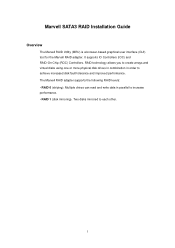
Marvell SATA3 RAID Installation Guide Overview The Marvell RAID Utility (MRU) is a browser-based graphical user interface (GUI) tool for the Marvell RAID adapter. Multiple drives can ...
Marvell SATA3 RAID Installation Guide Overview The Marvell RAID Utility (MRU) is a browser-based graphical user interface (GUI) tool for the Marvell RAID adapter. Multiple drives can ...
Marvell SATA3 RAID Installation Guide
Page 2
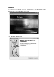
Click "Install all" or "Marvell SATA3 Driver". The system will start to the optical drive. Click "Next" at the welcome screen. 2 Installation Insert ASRock support CD to auto-install Marvell SATA3 driver.
Click "Install all" or "Marvell SATA3 Driver". The system will start to the optical drive. Click "Next" at the welcome screen. 2 Installation Insert ASRock support CD to auto-install Marvell SATA3 driver.
Marvell SATA3 RAID Installation Guide
Page 12
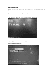
Press . 12 Press + during the POST to create virtual disk on this array. In Marvell BIOS Setup screen, select free disks to create array and continue to enter Marvell BIOS Setup screen. Marvell RAID ROM Besides Marvell SATA3 RAID utility, you need to configure RAID functions. First of all, you can also use Marvell RAID ROM to make a SATA3 driver diskette.
Press . 12 Press + during the POST to create virtual disk on this array. In Marvell BIOS Setup screen, select free disks to create array and continue to enter Marvell BIOS Setup screen. Marvell RAID ROM Besides Marvell SATA3 RAID utility, you need to configure RAID functions. First of all, you can also use Marvell RAID ROM to make a SATA3 driver diskette.
User Manual
Page 3
...Dr. Debug 38 2.14 HDMI_SPDIF Header Connection Guide 41 2.15 Serial ATA (SATA) / Serial ATAII (SATAII) / Serial ATA3 (SATA3) Hard Disks Installation 42 2.16 Serial ATA3 (SATA3) Hard Disks Installation 42 2.17 Hot Plug and Hot Swap Functions for SATA / SATAII HDDs 43 2.18 Hot Plug and Hot Swap... Functions for SATA3 HDDs ... 43 2.19 SATA / SATAII / SATA3 HDD Hot Plug Feature and Operation Guide 44 2.20 Driver Installation Guide 46 2.21 Installing Windows® 7 / 7 64-bit / ...
...Dr. Debug 38 2.14 HDMI_SPDIF Header Connection Guide 41 2.15 Serial ATA (SATA) / Serial ATAII (SATAII) / Serial ATA3 (SATA3) Hard Disks Installation 42 2.16 Serial ATA3 (SATA3) Hard Disks Installation 42 2.17 Hot Plug and Hot Swap Functions for SATA / SATAII HDDs 43 2.18 Hot Plug and Hot Swap... Functions for SATA3 HDDs ... 43 2.19 SATA / SATAII / SATA3 HDD Hot Plug Feature and Operation Guide 44 2.20 Driver Installation Guide 46 2.21 Installing Windows® 7 / 7 64-bit / ...
User Manual
Page 7
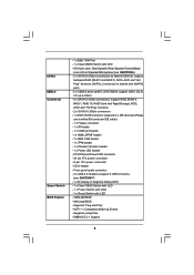
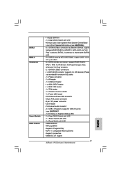
...to 5Gb/s - 6 x SATAII 3.0Gb/s connectors, support RAID (RAID 0, RAID 1, RAID 10, RAID 5 and Intel Rapid Storage), NCQ, AHCI and "Hot Plug" functions - 2 x SATA3 6.0Gb/s connectors - 1 x ATA133 IDE connector (supports 2 x IDE devices) (Please use bundled 80-conductor IDE cable) - 1 x Floppy connector - 1 x IR header - 1 ...Segment Debug LED) - 1 x Clear CMOS Switch with LED - 1 x Power Switch with LED - 1 x Reset Switch with LED - Supports jumperfree - SATA3 USB3.0 Connector Smart Switch BIOS Feature - 1 x IEEE 1394 Port - 1 x Clear CMOS Switch with LED - 16Mb AMI BIOS - CPU/Chassis/Power ...
...to 5Gb/s - 6 x SATAII 3.0Gb/s connectors, support RAID (RAID 0, RAID 1, RAID 10, RAID 5 and Intel Rapid Storage), NCQ, AHCI and "Hot Plug" functions - 2 x SATA3 6.0Gb/s connectors - 1 x ATA133 IDE connector (supports 2 x IDE devices) (Please use bundled 80-conductor IDE cable) - 1 x Floppy connector - 1 x IR header - 1 ...Segment Debug LED) - 1 x Clear CMOS Switch with LED - 1 x Power Switch with LED - 1 x Reset Switch with LED - Supports jumperfree - SATA3 USB3.0 Connector Smart Switch BIOS Feature - 1 x IEEE 1394 Port - 1 x Clear CMOS Switch with LED - 16Mb AMI BIOS - CPU/Chassis/Power ...
User Manual
Page 12
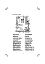
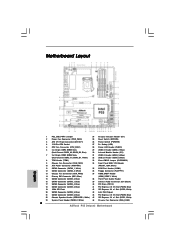
... MIC IN 46 45 44 43 42 41 40 39 38 PCIE1 LAN PHY PCIE2 CHA_FAN3 CHA_FAN2 IDE1 EuP Ready SATA3 6Gb/s SATAII_5_6 SATAII_3_4 SATAII_1_2 PCIE3 Super I/O P55 Deluxe3 Intel P55 PCIE4 PCI Express 2.0 1394a AUDIO CODEC HD_AUDIO1 1 CD1 HDMI_SPDIF1 1 FLOPPY1 PCI1 RoHS PCI2 COM1 1 CMOS Battery ...2.0 x16 Slot (PCIE4, Blue) 19 16Mb SPI Flash 42 PCI Express 2.0 x1 Slot (PCIE3, White) 20 SATAII Connector (SATAII_5, Blue ) 43 Intel P55 Chipset 21 SATAII Connector (SATAII_6, Blue ) 44 PCI Express 2.0 x16 Slot (PCIE2, Blue) 22 Chassis Speaker Header (SPEAKER 1, White) 45 PCI Express ...
... MIC IN 46 45 44 43 42 41 40 39 38 PCIE1 LAN PHY PCIE2 CHA_FAN3 CHA_FAN2 IDE1 EuP Ready SATA3 6Gb/s SATAII_5_6 SATAII_3_4 SATAII_1_2 PCIE3 Super I/O P55 Deluxe3 Intel P55 PCIE4 PCI Express 2.0 1394a AUDIO CODEC HD_AUDIO1 1 CD1 HDMI_SPDIF1 1 FLOPPY1 PCI1 RoHS PCI2 COM1 1 CMOS Battery ...2.0 x16 Slot (PCIE4, Blue) 19 16Mb SPI Flash 42 PCI Express 2.0 x1 Slot (PCIE3, White) 20 SATAII Connector (SATAII_5, Blue ) 43 Intel P55 Chipset 21 SATAII Connector (SATAII_6, Blue ) 44 PCI Express 2.0 x16 Slot (PCIE2, Blue) 22 Chassis Speaker Header (SPEAKER 1, White) 45 PCI Express ...
User Manual
Page 31
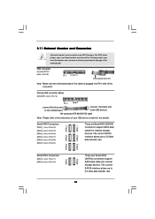
The current SATA3 interface allows up to the instruction of the motherboard! FDD connector (33-pin FLOPPY1) (see p.12 No. 14) PIN1 IDE1 connect the blue end to ...: see p.12, No. 18) (SATAII_4: see p.12, No. 17) (SATAII_5: see p.12, No. 20) (SATAII_6: see p.12, No. 12) SATA3_1 SATA3_2 These two Serial ATA3 (SATA3) connectors support SATA data cables for the details. Do NOT place jumper caps over the headers and connectors will cause permanent damage of your IDE...
The current SATA3 interface allows up to the instruction of the motherboard! FDD connector (33-pin FLOPPY1) (see p.12 No. 14) PIN1 IDE1 connect the blue end to ...: see p.12, No. 18) (SATAII_4: see p.12, No. 17) (SATAII_5: see p.12, No. 20) (SATAII_6: see p.12, No. 12) SATA3_1 SATA3_2 These two Serial ATA3 (SATA3) connectors support SATA data cables for the details. Do NOT place jumper caps over the headers and connectors will cause permanent damage of your IDE...
User Manual
Page 32
... GND NC LAD2 LAD1 GND NC SERIRQ CLKRUN NC Either end of the SATA data cable can be connected to the SATA / SATAII / SATA3 hard disk or the SATAII / SATA3 connector on this motherboard. A TPM system also helps enhance network security, protects digital identities, and ensures platform integrity. 32 Besides five default...
... GND NC LAD2 LAD1 GND NC SERIRQ CLKRUN NC Either end of the SATA data cable can be connected to the SATA / SATAII / SATA3 hard disk or the SATAII / SATA3 connector on this motherboard. A TPM system also helps enhance network security, protects digital identities, and ensures platform integrity. 32 Besides five default...
User Manual
Page 42
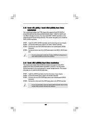
... disks on this motherboard for internal storage devices. 2.15 Serial ATA (SATA) / Serial ATAII (SATAII) Hard Disks Installation This motherboard adopts Intel® P55 chipset that supports Serial ATA3 (SATA3) hard disks and RAID (RAID 0 and RAID 1) functions. STEP 1: Install the SATA / SATAII hard disks into the drive bays of your chassis...
... disks on this motherboard for internal storage devices. 2.15 Serial ATA (SATA) / Serial ATAII (SATAII) Hard Disks Installation This motherboard adopts Intel® P55 chipset that supports Serial ATA3 (SATA3) hard disks and RAID (RAID 0 and RAID 1) functions. STEP 1: Install the SATA / SATAII hard disks into the drive bays of your chassis...
User Manual
Page 43
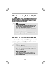
Intel® P55 chipset provides hardware support for Advanced Host controller Interface (AHCI), a new programming interface for SATA host controllers developed thru a joint industry effort. However, please note that it cannot perform Hot Plug if the OS has been installed into the SATA3 HDD. Marvell SE9128 chipset provides hardware ...the SATA / SATAII HDDs while the system is still power-on and in RAID / AHCI mode. NOTE What is Hot Swap Function? If the SATA3 HDDs are NOT set for RAID configuration, it is called "Hot Plug" for SATA / SATAII in RAID / AHCI mode. 2.17 Hot Plug ...
Intel® P55 chipset provides hardware support for Advanced Host controller Interface (AHCI), a new programming interface for SATA host controllers developed thru a joint industry effort. However, please note that it cannot perform Hot Plug if the OS has been installed into the SATA3 HDD. Marvell SE9128 chipset provides hardware ...the SATA / SATAII HDDs while the system is still power-on and in RAID / AHCI mode. NOTE What is Hot Swap Function? If the SATA3 HDDs are NOT set for RAID configuration, it is called "Hot Plug" for SATA / SATAII in RAID / AHCI mode. 2.17 Hot Plug ...
User Manual
Page 44
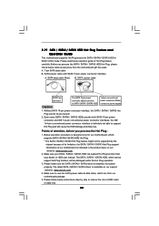
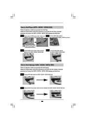
... indicated in RAID / AHCI mode. Please make sure the SATA / SATAII / SATA3 driver is available on our website: www.asrock.com 2. Without SATA 15-pin power connector interface, the SATA / SATAII / SATA3 Hot Plug cannot be damaged under the Hot Plug operation. 3. Before you process...feature carefully. Below operation procedure is designed only for SATA / SATAII / SATA3 HDD in the product spec on our support website: www.asrock.com 4. A. 7-pin SATA data cable B. 2.19 SATA / SATAII / SATA3 HDD Hot Plug Feature and Operation Guide This motherboard supports Hot Plug feature for...
... indicated in RAID / AHCI mode. Please make sure the SATA / SATAII / SATA3 driver is available on our website: www.asrock.com 2. Without SATA 15-pin power connector interface, the SATA / SATAII / SATA3 Hot Plug cannot be damaged under the Hot Plug operation. 3. Before you process...feature carefully. Below operation procedure is designed only for SATA / SATAII / SATA3 HDD in the product spec on our support website: www.asrock.com 4. A. 7-pin SATA data cable B. 2.19 SATA / SATAII / SATA3 HDD Hot Plug Feature and Operation Guide This motherboard supports Hot Plug feature for...
User Manual
Page 45
...Step 3 Connect SATA 15-pin power cable connector (Black) end to process the Hot Unplug, improper procedure will cause the SATA / SATAII / SATA3 HDD damage and data loss. Step 4 Connect SATA data cable to process the Hot Plug, improper procedure will cause the SATA / SATAII..., before you process the Hot Unplug: Please do follow below instruction sequence to the SATA / SATAII / SATA3 HDD. the motherboard's SATAII / SATA3 connector. Step 1 Unplug SATA data cable from SATA / SATAII / SATA3 HDD side. 45 Step 1 Please connect SATA power cable 1x4-pin end Step 2 Connect SATA data cable...
...Step 3 Connect SATA 15-pin power cable connector (Black) end to process the Hot Unplug, improper procedure will cause the SATA / SATAII / SATA3 HDD damage and data loss. Step 4 Connect SATA data cable to process the Hot Plug, improper procedure will cause the SATA / SATAII..., before you process the Hot Unplug: Please do follow below instruction sequence to the SATA / SATAII / SATA3 HDD. the motherboard's SATAII / SATA3 connector. Step 1 Unplug SATA data cable from SATA / SATAII / SATA3 HDD side. 45 Step 1 Please connect SATA power cable 1x4-pin end Step 2 Connect SATA data cable...
User Manual
Page 47
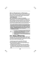
... "Intel Rapid Storage" in the folder at a later date by booting from the Support CD again so that "Intel Rapid Storage" will be presented. Marvell SATA3 RAID Utility does not support rebuild function under Marvell RAID ROM. 2.21.2 Setting Up a "RAID Ready" System You can be presented. When done, exit Setup...
... "Intel Rapid Storage" in the folder at a later date by booting from the Support CD again so that "Intel Rapid Storage" will be presented. Marvell SATA3 RAID Utility does not support rebuild function under Marvell RAID ROM. 2.21.2 Setting Up a "RAID Ready" System You can be presented. When done, exit Setup...

User Manual
Page 48
... can follow the procedures of the hard drive already in order to extend any data on the destination hard drive will need another SATA / SATAII / SATA3 hard drive with your motherboard or after downloading it as the source hard drive. 1. It's important to a two drive RAID 0, RAID 1 configuration or three drive...
... can follow the procedures of the hard drive already in order to extend any data on the destination hard drive will need another SATA / SATAII / SATA3 hard drive with your motherboard or after downloading it as the source hard drive. 1. It's important to a two drive RAID 0, RAID 1 configuration or three drive...

User Manual
Page 49
... left on your system as well. 2. If you need to check the installation guide in the Support CD for RAID configuration. page, please insert the ASRock Support CD into your system. After the installation of Windows® 7 / 7 64-bit / VistaTM / VistaTM 64-bit OS, if you want to manage ... the Windows® 7 / 7 64-bit / VistaTM / VistaTM 64-bit optical disk into the optical drive to boot your system, and follow below steps. Marvell SATA3 RAID Utility does not support rebuild function under Marvell RAID ROM. 49 Please refer to the document in the Support CD, "Guide to SATA Hard...
... left on your system as well. 2. If you need to check the installation guide in the Support CD for RAID configuration. page, please insert the ASRock Support CD into your system. After the installation of Windows® 7 / 7 64-bit / VistaTM / VistaTM 64-bit OS, if you want to manage ... the Windows® 7 / 7 64-bit / VistaTM / VistaTM 64-bit optical disk into the optical drive to boot your system, and follow below steps. Marvell SATA3 RAID Utility does not support rebuild function under Marvell RAID ROM. 49 Please refer to the document in the Support CD, "Guide to SATA Hard...
User Manual
Page 64
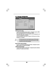
... Configuration" will appear. SATAII Operation Mode Use this to select Marvell SATA3 Operation Mode. 3.4.4 Storage Configuration BIOS SETUP UTILITY Advanced Storage Configuration SATA Operation Mode SATAII 1,2,3,4 Configuration SATAII 5,6 Configuration Marvell SATA3 Operation Mode eSATA Compatible Mode [IDE] [Compatible] [Enhanced] [IDE... American Megatrends, Inc. Configuration options: [IDE], [RAID], [AHCI] and [Disabled]. The default value is [IDE]. Marvell SATA3 Operation Mode Use this to select eSATA Compatible Mode. If you select [RAID] or [AHCI] mode, the options "Hot Plug...
... Configuration" will appear. SATAII Operation Mode Use this to select Marvell SATA3 Operation Mode. 3.4.4 Storage Configuration BIOS SETUP UTILITY Advanced Storage Configuration SATA Operation Mode SATAII 1,2,3,4 Configuration SATAII 5,6 Configuration Marvell SATA3 Operation Mode eSATA Compatible Mode [IDE] [Compatible] [Enhanced] [IDE... American Megatrends, Inc. Configuration options: [IDE], [RAID], [AHCI] and [Disabled]. The default value is [IDE]. Marvell SATA3 Operation Mode Use this to select eSATA Compatible Mode. If you select [RAID] or [AHCI] mode, the options "Hot Plug...
Quick Installation Guide
Page 2
... (CHA_FAN1) 34 Front Panel IEEE 1394 Header 10 ATX Power Connector (ATXPWR1) (FRONT_1394, White) 11 SATA3 Connector (SATA3_1, White) 35 COM Port Header (COM1) 12 SATA3 Connector (SATA3_2, White) 36 Floppy Connector (FLOPPY1) 13 Chassis Fan Connector (CHA_FAN2) 37 HDMI_SPDIF Header ... ) 43 Intel P55 Chipset 21 SATAII Connector (SATAII_6, Blue ) 44 PCI Express 2.0 x16 Slot (PCIE2, Blue) 22 Chassis Speaker Header (SPEAKER 1, White) 45 PCI Express 2.0 x1 Slot (PCIE1, White) 23 System Panel Header (PANEL1, White) 46 Chassis Fan Connector (CHA_FAN2) 2 ASRock P55 Deluxe3 Motherboard
... (CHA_FAN1) 34 Front Panel IEEE 1394 Header 10 ATX Power Connector (ATXPWR1) (FRONT_1394, White) 11 SATA3 Connector (SATA3_1, White) 35 COM Port Header (COM1) 12 SATA3 Connector (SATA3_2, White) 36 Floppy Connector (FLOPPY1) 13 Chassis Fan Connector (CHA_FAN2) 37 HDMI_SPDIF Header ... ) 43 Intel P55 Chipset 21 SATAII Connector (SATAII_6, Blue ) 44 PCI Express 2.0 x16 Slot (PCIE2, Blue) 22 Chassis Speaker Header (SPEAKER 1, White) 45 PCI Express 2.0 x1 Slot (PCIE1, White) 23 System Panel Header (PANEL1, White) 46 Chassis Fan Connector (CHA_FAN2) 2 ASRock P55 Deluxe3 Motherboard
Quick Installation Guide
Page 7
... AMI BIOS - Front panel audio connector - 3 x USB 2.0 headers (support 6 USB 2.0 ports) (see CAUTION 6) - 2 x SATA3 6.0Gb/s connectors by Marvell SE9128, support hardware RAID (RAID 0 and RAID 1), NCQ, AHCI and "Hot Plug" functions (SATA3_2 connector is...SATA3 6.0Gb/s connectors - 1 x ATA133 IDE connector (supports 2 x IDE devices) (Please use bundled 80-conductor IDE cable) - 1 x Floppy connector - 1 x IR header - 1 x COM port header - 1 x HDMI_SPDIF header - 1 x IEEE 1394 header - 1 x TPM header - 1 x Chassis Intrusion header - 1 x Power LED header - SMBIOS 2.3.1 Support 7 ASRock P55 Deluxe3...
... AMI BIOS - Front panel audio connector - 3 x USB 2.0 headers (support 6 USB 2.0 ports) (see CAUTION 6) - 2 x SATA3 6.0Gb/s connectors by Marvell SE9128, support hardware RAID (RAID 0 and RAID 1), NCQ, AHCI and "Hot Plug" functions (SATA3_2 connector is...SATA3 6.0Gb/s connectors - 1 x ATA133 IDE connector (supports 2 x IDE devices) (Please use bundled 80-conductor IDE cable) - 1 x Floppy connector - 1 x IR header - 1 x COM port header - 1 x HDMI_SPDIF header - 1 x IEEE 1394 header - 1 x TPM header - 1 x Chassis Intrusion header - 1 x Power LED header - SMBIOS 2.3.1 Support 7 ASRock P55 Deluxe3...
Quick Installation Guide
Page 25
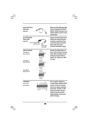
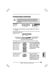
Do NOT place jumper caps over the headers and connectors will cause permanent damage of the motherboard! The current SATA3 interface allows up to 6.0 Gb/s data transfer rate. 25 ASRock P55 Deluxe3 Motherboard Serial ATAII Connectors (SATAII_1: see p.2, No. 16) (SATAII_2: see p.2, No. 15) (SATAII_3: see... devices. Primary IDE connector (Blue) (39-pin IDE1, see p.2, No. 12) SATA3_1 SATA3_2 These two Serial ATA3 (SATA3) connectors support SATA data cables for internal storage devices. SATAII_5 SATAII_3 SATAII_1 SATAII_6 SATAII_4 SATAII_2 English Serial ATA3 Connectors (SATA3_1: ...
Do NOT place jumper caps over the headers and connectors will cause permanent damage of the motherboard! The current SATA3 interface allows up to 6.0 Gb/s data transfer rate. 25 ASRock P55 Deluxe3 Motherboard Serial ATAII Connectors (SATAII_1: see p.2, No. 16) (SATAII_2: see p.2, No. 15) (SATAII_3: see... devices. Primary IDE connector (Blue) (39-pin IDE1, see p.2, No. 12) SATA3_1 SATA3_2 These two Serial ATA3 (SATA3) connectors support SATA data cables for internal storage devices. SATAII_5 SATAII_3 SATAII_1 SATAII_6 SATAII_4 SATAII_2 English Serial ATA3 Connectors (SATA3_1: ...
Quick Installation Guide
Page 26
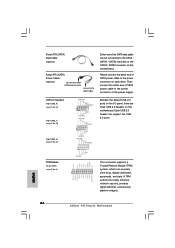
...digital identities, and ensures platform integrity. Please connect the black end of SATA power cable to the SATA / SATAII / SATA3 hard disk or the SATAII / SATA3 connector on this motherboard. Serial ATA (SATA) Data Cable (Optional) Serial ATA (SATA) Power Cable (Optional) connect ... store keys, digital certificates, passwords, and data. Then connect the white end of SATA power cable to the power connector of the power supply. ASRock P55 Deluxe3 Motherboard USB 2.0 Headers (9-pin USB8_9) (see p.2 No. 32) (9-pin USB6_7) (see p.2 No. 8) 26 This connector supports a Trusted Platform...
...digital identities, and ensures platform integrity. Please connect the black end of SATA power cable to the SATA / SATAII / SATA3 hard disk or the SATAII / SATA3 connector on this motherboard. Serial ATA (SATA) Data Cable (Optional) Serial ATA (SATA) Power Cable (Optional) connect ... store keys, digital certificates, passwords, and data. Then connect the white end of SATA power cable to the power connector of the power supply. ASRock P55 Deluxe3 Motherboard USB 2.0 Headers (9-pin USB8_9) (see p.2 No. 32) (9-pin USB6_7) (see p.2 No. 8) 26 This connector supports a Trusted Platform...