User Manual
Page 3
...Menu 28 4. Exit Menu 30 3 Boot Setup Menu 29 5. Advanced BIOS Setup Menu 22 2. Contents 1 Introduction 4 1.1 Package Contents 4 1.2 Specifications 5 1.3 Motherboard Layout 8 1.4 ASRock I/OTM 9 2 Installation 10 2.1 Screw Holes 10 2.2 Pre-installation Precautions 10 2.3 CPU Installation 11 2.4 Installation of CPU fan and Heatsink 11 2.5 Installation of... Operating System 21 4.2 Support CD Information 21 4.2.1 Running Support CD 21 4.2.2 Drivers Menu 21 4.2.3 Utilities Menu 21 4.2.4 ASRock "PC-DIY Live Demo" Program 21 4.2.5 Contact Information 21 Appendix 22 1.
...Menu 28 4. Exit Menu 30 3 Boot Setup Menu 29 5. Advanced BIOS Setup Menu 22 2. Contents 1 Introduction 4 1.1 Package Contents 4 1.2 Specifications 5 1.3 Motherboard Layout 8 1.4 ASRock I/OTM 9 2 Installation 10 2.1 Screw Holes 10 2.2 Pre-installation Precautions 10 2.3 CPU Installation 11 2.4 Installation of CPU fan and Heatsink 11 2.5 Installation of... Operating System 21 4.2 Support CD Information 21 4.2.1 Running Support CD 21 4.2.2 Drivers Menu 21 4.2.3 Utilities Menu 21 4.2.4 ASRock "PC-DIY Live Demo" Program 21 4.2.5 Contact Information 21 Appendix 22 1.

User Manual
Page 4
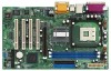
... might be updated, the content of this manual will be subject to quality and endurance. ASRock website http://www.asrock.com 1.1 Package Contents ASRock P4i45PE-C Motherboard (ATX Form Factor: 12.0-in x 7.0-in, 30.5 cm x 17.8 cm) ASRock P4i45PE-C Quick Installation Guide ASRock P4i45PE-C Support CD One 80-conductor Ultra ATA 66/100 IDE Ribbon Cable One Ribbon Cable for...
... might be updated, the content of this manual will be subject to quality and endurance. ASRock website http://www.asrock.com 1.1 Package Contents ASRock P4i45PE-C Motherboard (ATX Form Factor: 12.0-in x 7.0-in, 30.5 cm x 17.8 cm) ASRock P4i45PE-C Quick Installation Guide ASRock P4i45PE-C Support CD One 80-conductor Ultra ATA 66/100 IDE Ribbon Cable One Ribbon Cable for...

User Manual
Page 6
... not recommended to perform over -clocking mode). While CPU overheat is detected, the system will also be fine tuned to the NOTE on P4i45PE-C motherboard! P4i45PE-C motherboard may cause the instability of "Hyper Threading Technology", please check page 22. 3. To improve heat dissipation, remember to Microsoft® official document at http://www....
... not recommended to perform over -clocking mode). While CPU overheat is detected, the system will also be fine tuned to the NOTE on P4i45PE-C motherboard! P4i45PE-C motherboard may cause the instability of "Hyper Threading Technology", please check page 22. 3. To improve heat dissipation, remember to Microsoft® official document at http://www....

User Manual
Page 7
... SIDE TTD7608F8E50B TMD7608F8E43B TMD7608F8E50B TTD7608F8E50B DOUBLE SIDE SINGLE SIDE SINGLE SIDE SINGLE SIDE Since the memory types are changing rapidly, please visit ASRock website (http://www.asrock.com/support/index.htm) for the latest recommended memory support list. 7 Set the "FSB" jumper to the tables below for...DDR1 DIMM. (If it is set to DDR 400 mode, then it does not support CL3 module.) The Recommended Memory Modules lists for P4i45PE-C motherboard. FSB 800 MHz / DDR 400 Mode DRAM SIZE TYPE CELL VENDOR (MB) VENDOR ADATA ADATA ADATA 512 DDR400 256 DDR450 256 DDR400 ...
... SIDE TTD7608F8E50B TMD7608F8E43B TMD7608F8E50B TTD7608F8E50B DOUBLE SIDE SINGLE SIDE SINGLE SIDE SINGLE SIDE Since the memory types are changing rapidly, please visit ASRock website (http://www.asrock.com/support/index.htm) for the latest recommended memory support list. 7 Set the "FSB" jumper to the tables below for...DDR1 DIMM. (If it is set to DDR 400 mode, then it does not support CL3 module.) The Recommended Memory Modules lists for P4i45PE-C motherboard. FSB 800 MHz / DDR 400 Mode DRAM SIZE TYPE CELL VENDOR (MB) VENDOR ADATA ADATA ADATA 512 DDR400 256 DDR450 256 DDR400 ...

User Manual
Page 10
...Holes Place screws into it on the carpet or the like. Failure to do not touch the ICs. 4. Before you install motherboard components or change any component. 2. Do not over-tighten the screws! Doing so may cause severe damage to ensure that comes...component. Hold components by circles to secure the motherboard to use a grounded wrist strap or touch a safety grounded object before installing or removing the motherboard. Chapter 2 Installation P4i45PE-C is detached from the wall socket before you install the motherboard, study the configuration of the following precautions ...
...Holes Place screws into it on the carpet or the like. Failure to do not touch the ICs. 4. Before you install motherboard components or change any component. 2. Do not over-tighten the screws! Doing so may cause severe damage to ensure that comes...component. Hold components by circles to secure the motherboard to use a grounded wrist strap or touch a safety grounded object before installing or removing the motherboard. Chapter 2 Installation P4i45PE-C is detached from the wall socket before you install the motherboard, study the configuration of the following precautions ...

User Manual
Page 12
... outward. Step 2. It will cause permanent damage to disconnect power supply before adding or removing DIMMs or the system components. 2.5 Installation of Memory Modules (DIMM) P4i45PE-C motherboard provides two 184-pin DDR (Double Data Rate) DIMM slots. Align a DIMM on the slot such that the notch on the DIMM matches the break... on the slot. Step 3. Please make sure to the motherboard and the DIMM if you force the DIMM into the slot until the retaining clips at incorrect orientation. Step 1.
... outward. Step 2. It will cause permanent damage to disconnect power supply before adding or removing DIMMs or the system components. 2.5 Installation of Memory Modules (DIMM) P4i45PE-C motherboard provides two 184-pin DDR (Double Data Rate) DIMM slots. Align a DIMM on the slot such that the notch on the DIMM matches the break... on the slot. Step 3. Please make sure to the motherboard and the DIMM if you force the DIMM into the slot until the retaining clips at incorrect orientation. Step 1.

User Manual
Page 13
AGP slot: The AGP slot is unplugged. The ASRock AGP slot has a special locking mechanism which can securely fasten the graphics card inserted. Before installing the ...that have the 32-bit PCI interface. Step 4. It may cause permanent damage! Remove the system unit cover (if your motherboard is completely seated on P4i45PE-C motherboard! Step 3. Installing an expansion card Step 1. Step 5. Fasten the card to the chassis with the slot and press ...Slots) There are used to install a graphics card. PCI slots: PCI slots are 4 PCI slots and 1 AGP slot on P4i45PE-C motherboard.
AGP slot: The AGP slot is unplugged. The ASRock AGP slot has a special locking mechanism which can securely fasten the graphics card inserted. Before installing the ...that have the 32-bit PCI interface. Step 4. It may cause permanent damage! Remove the system unit cover (if your motherboard is completely seated on P4i45PE-C motherboard! Step 3. Installing an expansion card Step 1. Step 5. Fasten the card to the chassis with the slot and press ...Slots) There are used to install a graphics card. PCI slots: PCI slots are 4 PCI slots and 1 AGP slot on P4i45PE-C motherboard.

User Manual
Page 15
...please connect your IDE device vendor for the details. Infrared module connector (5-pin IR1) (see p.8 item 18) USB_PWR P-5 P+5 GND DUMMY 1 GND P+4 P-4 USB_PWR ASRock I/OTM provides you use only one IDE device on the rear panel. USB 2.0 Header (9-pin USB45) (see p.8 item 17) IRTX +5V DUMMY 1 GND IRRX ... (IDE1, blue) and CD-ROM to the IDE devices 80-conductor ATA 66/100 cable Note: If you 4 default USB 2.0 ports on this motherboard, please set the IDE device as "Master". Connector FDD connector (33-pin FLOPPY1) (see p.8 item 8) PIN1 IDE1 PIN1 IDE2 connect the blue ...
...please connect your IDE device vendor for the details. Infrared module connector (5-pin IR1) (see p.8 item 18) USB_PWR P-5 P+5 GND DUMMY 1 GND P+4 P-4 USB_PWR ASRock I/OTM provides you use only one IDE device on the rear panel. USB 2.0 Header (9-pin USB45) (see p.8 item 17) IRTX +5V DUMMY 1 GND IRRX ... (IDE1, blue) and CD-ROM to the IDE devices 80-conductor ATA 66/100 cable Note: If you 4 default USB 2.0 ports on this motherboard, please set the IDE device as "Master". Connector FDD connector (33-pin FLOPPY1) (see p.8 item 8) PIN1 IDE1 PIN1 IDE2 connect the blue ...
User Manual
Page 17
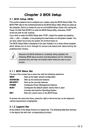
The BIOS FWH chip on the motherboard stores the BIOS Setup Utility. Press during the Power-On-Self-Test (POST) to enter the BIOS Setup Utility, otherwise, POST continues with its various ...
The BIOS FWH chip on the motherboard stores the BIOS Setup Utility. Press during the Power-On-Self-Test (POST) to enter the BIOS Setup Utility, otherwise, POST continues with its various ...

User Manual
Page 21
...® Media Player® to play the file. 4.2.5 Contact Information If you may contact your computer. Because motherboard settings and hardware options vary, use the setup procedures in this demo program, you need to contact ASRock or want to know more information. 4.2 Support CD Information The Support CD that came with the...
...® Media Player® to play the file. 4.2.5 Contact Information If you may contact your computer. Because motherboard settings and hardware options vary, use the setup procedures in this demo program, you need to contact ASRock or want to know more information. 4.2 Support CD Information The Support CD that came with the...

User Manual
Page 22
...SDRAM Frequency Hyper Threading Technology Disabled Auto 133MHz Locked Auto Auto [ Setup Help ] to enable or disable the feature of the installed motherboard. CPU Host Frequency: This shows current CPU host frequency of spread spectrum. For the setting of FSB 400, you may select [133MHz... of FSB 533, you the following BIOS Setup menus: "Advanced," "Security," "Power," "Boot," and "Exit." 1. Set to [Auto], the motherboard will introduce you may select [133MHz (DDR 266)] as the operating frequency. This option will equal the core speed of the installed processor. Appendix: ...
...SDRAM Frequency Hyper Threading Technology Disabled Auto 133MHz Locked Auto Auto [ Setup Help ] to enable or disable the feature of the installed motherboard. CPU Host Frequency: This shows current CPU host frequency of spread spectrum. For the setting of FSB 400, you may select [133MHz... of FSB 533, you the following BIOS Setup menus: "Advanced," "Security," "Power," "Boot," and "Exit." 1. Set to [Auto], the motherboard will introduce you may select [133MHz (DDR 266)] as the operating frequency. This option will equal the core speed of the installed processor. Appendix: ...

User Manual
Page 26
.... OnBoard LAN: This allows you to enable or disable the on your system. OnBoard AC'97 Audio: Select [Enabled], [Auto] or [Disabled] for CPU temperature, Motherboard temperature, CPU fan speed, and critical voltage. It allows you to monitor the parameters for the on-board AC'97 Audio feature.
.... OnBoard LAN: This allows you to enable or disable the on your system. OnBoard AC'97 Audio: Select [Enabled], [Auto] or [Disabled] for CPU temperature, Motherboard temperature, CPU fan speed, and critical voltage. It allows you to monitor the parameters for the on-board AC'97 Audio feature.

