
User Manual
Page 3
... Menu 30 4. Boot Setup Menu 31 5. Contents 1 Introduction 4 1.1 Package Contents 4 1.2 Specifications 5 1.3 Supported AGP VGA Cards List 8 1.4 Motherboard Layout 10 1.5 ASRock I/OTM 12 2 Installation 13 Pre-installation Precautions 13 2.1 CPU Installation 14 2.2 Installation of CPU fan and Heatsink 14 2.3 Installation of Memory Modules (... Operating System 24 4.2 Support CD Information 24 4.2.1 Running Support CD 24 4.2.2 Drivers Menu 24 4.2.3 Utilities Menu 24 4.2.4 ASRock "PC-DIY Live Demo" Program 24 4.2.5 Contact Information 24 Appendix 25 1. Security Setup Menu 29 3.
... Menu 30 4. Boot Setup Menu 31 5. Contents 1 Introduction 4 1.1 Package Contents 4 1.2 Specifications 5 1.3 Supported AGP VGA Cards List 8 1.4 Motherboard Layout 10 1.5 ASRock I/OTM 12 2 Installation 13 Pre-installation Precautions 13 2.1 CPU Installation 14 2.2 Installation of CPU fan and Heatsink 14 2.3 Installation of Memory Modules (... Operating System 24 4.2 Support CD Information 24 4.2.1 Running Support CD 24 4.2.2 Drivers Menu 24 4.2.3 Utilities Menu 24 4.2.4 ASRock "PC-DIY Live Demo" Program 24 4.2.5 Contact Information 24 Appendix 25 1. Security Setup Menu 29 3.

User Manual
Page 4
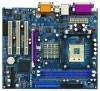
... change without further notice. ASRock website: http://www.asrock.com 1.1 Package Contents ASRock P4i45GL/P4i45GV motherboard (Micro ATX Form Factor: 9.6-in x 8.2-in, 24.4 cm x 20.8 cm) ASRock P4i45GL/P4i45GV Quick Installation Guide ASRock P4i45GL/P4i45GV Support CD One 80-conductor Ultra ATA 66/100 IDE Ribbon Cable One Ribbon Cable for purchasing ASRock P4i45GL/P4i45GV motherboard, a reliable motherboard produced under ASRock's consistently stringent quality...
... change without further notice. ASRock website: http://www.asrock.com 1.1 Package Contents ASRock P4i45GL/P4i45GV motherboard (Micro ATX Form Factor: 9.6-in x 8.2-in, 24.4 cm x 20.8 cm) ASRock P4i45GL/P4i45GV Quick Installation Guide ASRock P4i45GL/P4i45GV Support CD One 80-conductor Ultra ATA 66/100 IDE Ribbon Cable One Ribbon Cable for purchasing ASRock P4i45GL/P4i45GV motherboard, a reliable motherboard produced under ASRock's consistently stringent quality...

User Manual
Page 6
...www.microsoft.com/whdc/hwdev/bus/USB/USB2support.mspx 9. The AGI [ASRock Graphics Interface] slot is detected, the system will not be fine tuned to support higher CPU bus frequencies on the motherboard functions properly before you install the PC system. 6. Please refer to .... It may not work properly under Microsoft® Windows® XP SP1/2000 SP4. Although this motherboard offers stepless control, it will support PC2700(DDR333) at FSB 533MHz. 5. P4i45GV motherboard will support PC2100(DDR266) and PC2800(DDR350). 3 About the setting of "Hyper Threading Technology", please...
...www.microsoft.com/whdc/hwdev/bus/USB/USB2support.mspx 9. The AGI [ASRock Graphics Interface] slot is detected, the system will not be fine tuned to support higher CPU bus frequencies on the motherboard functions properly before you install the PC system. 6. Please refer to .... It may not work properly under Microsoft® Windows® XP SP1/2000 SP4. Although this motherboard offers stepless control, it will support PC2700(DDR333) at FSB 533MHz. 5. P4i45GV motherboard will support PC2100(DDR266) and PC2800(DDR350). 3 About the setting of "Hyper Threading Technology", please...

User Manual
Page 7
... INFINEON HYB25D256800BT-5 SINGLE SIDE TRANSCEND 256 DDR333 SAMSUNG K4H560838D-TCB3 SINGLE SIDE Since the memory types are changing rapidly, please visit ASRock website (http://www.asrock.com/support/index.htm) for P4i45GL motherboard. NOTE P4i45GL may be fine tuned to the table below for the details. FSB 533MHz / DDR350 Mode DRAM SIZE TYPE...
... INFINEON HYB25D256800BT-5 SINGLE SIDE TRANSCEND 256 DDR333 SAMSUNG K4H560838D-TCB3 SINGLE SIDE Since the memory types are changing rapidly, please visit ASRock website (http://www.asrock.com/support/index.htm) for P4i45GL motherboard. NOTE P4i45GL may be fine tuned to the table below for the details. FSB 533MHz / DDR350 Mode DRAM SIZE TYPE...
User Manual
Page 13
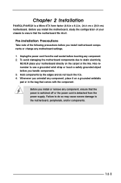
... P4i45GL/P4i45GV is detached from the wall socket before you uninstall any component. 2. Before you install motherboard components or change any component, ensure that the power is switched off or the power cord is a Micro ATX form factor (9.6-in x 8.2-in the bag that the motherboard fits into...to use a grounded wrist strap or touch a safety grounded object before touching any component, place it . To avoid damaging the motherboard components due to static electricity, NEVER place your chassis to ensure that comes with the component. Unplug the power cord from the power...
... P4i45GL/P4i45GV is detached from the wall socket before you uninstall any component. 2. Before you install motherboard components or change any component, ensure that the power is switched off or the power cord is a Micro ATX form factor (9.6-in x 8.2-in the bag that the motherboard fits into...to use a grounded wrist strap or touch a safety grounded object before touching any component, place it . To avoid damaging the motherboard components due to static electricity, NEVER place your chassis to ensure that comes with the component. Unplug the power cord from the power...
User Manual
Page 15
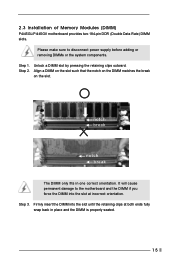
...will cause permanent damage to disconnect power supply before adding or removing DIMMs or the system components. Step 1. 2.3 Installation of Memory Modules (DIMM) P4i45GL/P4i45GV motherboard provides two 184-pin DDR (Double Data Rate) DIMM slots. Unlock a DIMM slot by pressing the retaining clips outward. Firmly insert the DIMM into the... slot at both ends fully snap back in one correct orientation. Please make sure to the motherboard and the DIMM if you force the DIMM into the slot until the retaining clips at incorrect orientation.
...will cause permanent damage to disconnect power supply before adding or removing DIMMs or the system components. Step 1. 2.3 Installation of Memory Modules (DIMM) P4i45GL/P4i45GV motherboard provides two 184-pin DDR (Double Data Rate) DIMM slots. Unlock a DIMM slot by pressing the retaining clips outward. Firmly insert the DIMM into the... slot at both ends fully snap back in one correct orientation. Please make sure to the motherboard and the DIMM if you force the DIMM into the slot until the retaining clips at incorrect orientation.
User Manual
Page 16
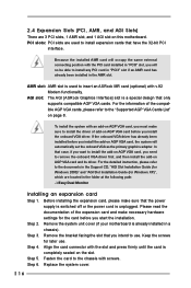
... system will occupy the same external connecting position with screws. For the information of the compatible AGP VGA cards, please refer to insert an ASRock MR card (optional) with the slot and press firmly until the card is a special design that have the 32-bit PCI interface. For... AGP VGA cards. Before installing the expansion card, please make sure that you start the installation. Please read the documentation of add-on this motherboard. Step 6. Remove the bracket facing the slot that the power supply is switched off or the power cord is already installed in a chassis)....
... system will occupy the same external connecting position with screws. For the information of the compatible AGP VGA cards, please refer to insert an ASRock MR card (optional) with the slot and press firmly until the card is a special design that have the 32-bit PCI interface. For... AGP VGA cards. Before installing the expansion card, please make sure that you start the installation. Please read the documentation of add-on this motherboard. Step 6. Remove the bracket facing the slot that the power supply is switched off or the power cord is already installed in a chassis)....

User Manual
Page 17
.... 24) JL1(see p.10/p.11, No. 18) 2-pin Jumper Note: CLRCMOS0 allows you do the clear-CMOS action. 17 Please rem ember to ASRock patented AGI8X Technology, this motherboard supports Easy Dual Monitor upgrade. Note: To select +5VSB, it down before you to short the pins on AGP VGA card, you must...
.... 24) JL1(see p.10/p.11, No. 18) 2-pin Jumper Note: CLRCMOS0 allows you do the clear-CMOS action. 17 Please rem ember to ASRock patented AGI8X Technology, this motherboard supports Easy Dual Monitor upgrade. Note: To select +5VSB, it down before you to short the pins on AGP VGA card, you must...

User Manual
Page 18
... default USB 2.0 ports. Infrared Module Header (5-pin IR1) (see p.10/p.11, No. 19) USB_PWR P-5 P+5 GND DUMMY 1 GND P+4 P-4 USB_PWR ASRock I /O panel are NOT jumpers. Placing jumper caps over these headers and connectors. Besides, to optimize compatibility and performance, please connect your IDE device vendor ...ROM to support 2 additional USB 2.0 ports. 2.7 Onboard Headers and Connectors Onboard headers and connectors are not sufficient, this motherboard, please set the IDE device as "Master". Do NOT place jumper caps over the headers and connectors will cause permanent damage of ...
... default USB 2.0 ports. Infrared Module Header (5-pin IR1) (see p.10/p.11, No. 19) USB_PWR P-5 P+5 GND DUMMY 1 GND P+4 P-4 USB_PWR ASRock I /O panel are NOT jumpers. Placing jumper caps over these headers and connectors. Besides, to optimize compatibility and performance, please connect your IDE device vendor ...ROM to support 2 additional USB 2.0 ports. 2.7 Onboard Headers and Connectors Onboard headers and connectors are not sufficient, this motherboard, please set the IDE device as "Master". Do NOT place jumper caps over the headers and connectors will cause permanent damage of ...

User Manual
Page 20
... you wish to enter the BIOS Setup after POST, restart the system by pressing + + , or by turning the system off and then back on the motherboard stores the BIOS Setup Utility. It is a menu-driven program, which allows you to run the BIOS Setup. If you see on your system using...
... you wish to enter the BIOS Setup after POST, restart the system by pressing + + , or by turning the system off and then back on the motherboard stores the BIOS Setup Utility. It is a menu-driven program, which allows you to run the BIOS Setup. If you see on your system using...

User Manual
Page 24
... to know more information. 4.2 Support CD Information The Support CD that came with the motherboard contains necessary drivers and useful utilities that the motherboard supports. Please install the necessary drivers to visit ASRock's website at http://www.asrock.com; Because motherboard settings and hardware options vary, use the setup procedures in this demo program, you...
... to know more information. 4.2 Support CD Information The Support CD that came with the motherboard contains necessary drivers and useful utilities that the motherboard supports. Please install the necessary drivers to visit ASRock's website at http://www.asrock.com; Because motherboard settings and hardware options vary, use the setup procedures in this demo program, you...

User Manual
Page 25
... and assigns appropriate frequency automatically. Advanced BIOS Setup Menu Main Advanced AMIBIOS SETUP UTILITY - SDRAM Frequency: If [Auto] is selected, the motherboard will introduce you the following BIOS Setup menus: "Advanced," "Security," "Power," "Boot," and "Exit." 1. Whether the option is ...This field should always be hidden if the current CPU does not support Hyper-Threading technology. 25 Hyper-Threading Technology (For P4i45GV Only): To enable this feature, it requires a computer system with an Intel Pentium®4 processor that supports Hyper-Threading ...
... and assigns appropriate frequency automatically. Advanced BIOS Setup Menu Main Advanced AMIBIOS SETUP UTILITY - SDRAM Frequency: If [Auto] is selected, the motherboard will introduce you the following BIOS Setup menus: "Advanced," "Security," "Power," "Boot," and "Exit." 1. Whether the option is ...This field should always be hidden if the current CPU does not support Hyper-Threading technology. 25 Hyper-Threading Technology (For P4i45GV Only): To enable this feature, it requires a computer system with an Intel Pentium®4 processor that supports Hyper-Threading ...
User Manual
Page 28
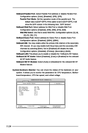
.... OnBoard MC'97 Modem: Select [Auto] or [Disabled] for Midi Port or disable Midi Port. It allows you to monitor the parameters for CPU temperature, Motherboard temperature, CPU fan speed, and critical voltage. VERSION 3.31a System Hardware Monitor [ Setup Help ] CPU Temperature M / B Temperature CPU FAN Speed Chassis FAN Speed Vcore + 3.30V...
.... OnBoard MC'97 Modem: Select [Auto] or [Disabled] for Midi Port or disable Midi Port. It allows you to monitor the parameters for CPU temperature, Motherboard temperature, CPU fan speed, and critical voltage. VERSION 3.31a System Hardware Monitor [ Setup Help ] CPU Temperature M / B Temperature CPU FAN Speed Chassis FAN Speed Vcore + 3.30V...

