
User Manual
Page 3
Advanced Menu ...Security Menu ...Power Menu ...Boot Menu ...Exit Menu ... 4 Software Support ...21 Appendix ...22 3 Contents 1 Introduction ...4 1.1 1.2 1.3 1.4 1.5 2.1 2.2 2.3 2.4 2.5 2.6 2.7 2.8 Package Contents ...Specifications ...Motherboard Layout (P4i45GL) ...Motherboard Layout (P4i45GV) ...ASRock I/OTM (P4i45GL / P4i45GV) ...Screw Holes ...Pre-installation Precautions ...CPU Installation ...Installation of Heatsink and CPU fan ...Installation of Memory Modules (DIMM) ...Expansion Slots ...Jumpers Setup ...Connectors ...4 5 8 9 10 ...
Advanced Menu ...Security Menu ...Power Menu ...Boot Menu ...Exit Menu ... 4 Software Support ...21 Appendix ...22 3 Contents 1 Introduction ...4 1.1 1.2 1.3 1.4 1.5 2.1 2.2 2.3 2.4 2.5 2.6 2.7 2.8 Package Contents ...Specifications ...Motherboard Layout (P4i45GL) ...Motherboard Layout (P4i45GV) ...ASRock I/OTM (P4i45GL / P4i45GV) ...Screw Holes ...Pre-installation Precautions ...CPU Installation ...Installation of Heatsink and CPU fan ...Installation of Memory Modules (DIMM) ...Expansion Slots ...Jumpers Setup ...Connectors ...4 5 8 9 10 ...

User Manual
Page 4
... manual will be available on ASRock website without notice. ASRock website http://www.asrock.com 1.1 Package Contents ASRock P4i45GL or P4i45GV motherboard (Micro ATX form factor: 9.6" x 7.0", 24.4 x 17.8 cm) ASRock P4i45GL / P4i45GV Quick Installation Guide ASRock Intel-Intel Support CD 1 cable for IDE devices (1 x ATA 66 / 100) 1 cable for purchasing ASRock P4i45GL / P4i45GV motherboard, a reliable motherboard produced under ASRock's consistently stringent quality control. Because...
... manual will be available on ASRock website without notice. ASRock website http://www.asrock.com 1.1 Package Contents ASRock P4i45GL or P4i45GV motherboard (Micro ATX form factor: 9.6" x 7.0", 24.4 x 17.8 cm) ASRock P4i45GL / P4i45GV Quick Installation Guide ASRock Intel-Intel Support CD 1 cable for IDE devices (1 x ATA 66 / 100) 1 cable for purchasing ASRock P4i45GL / P4i45GV motherboard, a reliable motherboard produced under ASRock's consistently stringent quality control. Because...

User Manual
Page 6
... other clocks, such as PCI clock and Memory clock will automatically shutdown. Supports jumperfree; Supports "Plug and Play"; Please check if the CPU fan on P4i45GL motherboard, it is not recommended to perform over clocking, other than the recommended CPU bus frequencies may not work properly under Microsoft® Windows® XP...
... other clocks, such as PCI clock and Memory clock will automatically shutdown. Supports jumperfree; Supports "Plug and Play"; Please check if the CPU fan on P4i45GL motherboard, it is not recommended to perform over clocking, other than the recommended CPU bus frequencies may not work properly under Microsoft® Windows® XP...

User Manual
Page 7
... K4H560838D-TCB3 K4H560838D-TCB3 TRANSCEND 256 APACER 256 Since the memory types are changing rapidly, please visit ASRock website (http://www.asrock.com/support/index.htm) for P4i45GL motherboard. P4i45GL The Recommended Memory Modules list for the latest recommended memory support list. 7 It supports DDR350 memory...VENDOR TWINMOS TWINMOS TWINMOS M.TEC WINBOND WINBOND ADATA KINGMAX KINGMAX MOSEL INFINEON MICRON MICRON INFINEON INFINEON SAMSUNG SAMSUNG CELL NO. NOTE P4i45GL may be fine tuned to the table below for the details. It supports DDR266 memory module at DDR DIMM1. 3. ...
... K4H560838D-TCB3 K4H560838D-TCB3 TRANSCEND 256 APACER 256 Since the memory types are changing rapidly, please visit ASRock website (http://www.asrock.com/support/index.htm) for P4i45GL motherboard. P4i45GL The Recommended Memory Modules list for the latest recommended memory support list. 7 It supports DDR350 memory...VENDOR TWINMOS TWINMOS TWINMOS M.TEC WINBOND WINBOND ADATA KINGMAX KINGMAX MOSEL INFINEON MICRON MICRON INFINEON INFINEON SAMSUNG SAMSUNG CELL NO. NOTE P4i45GL may be fine tuned to the table below for the details. It supports DDR266 memory module at DDR DIMM1. 3. ...
User Manual
Page 8
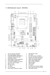
1.3 Motherboard Layout (P4i45GL) 1 2 3 4 17.8cm (7.0 in) 5 6 PS/2 Mouse 1 PS2_USB_PWR1 PARALLEL PORT Keyboard mPGA478B VGA LAN (optional) USB 2.0 Ports 28 USB 2.0 Ports DDR1 (64/72 bit, 184-pin module) ... (USB45, Blue) Floppy Connector (FLOPPY1) AMR Slot (AMR1) AUDIO CODEC JL1 Jumper Front Panel Audio Connector (AUDIO1) Internal Audio Connector: AUX1 (White) North Bridge Controller P4i45GL PANEL 1 IDE1 IDE2 ATXPWR1 PS/2 8
1.3 Motherboard Layout (P4i45GL) 1 2 3 4 17.8cm (7.0 in) 5 6 PS/2 Mouse 1 PS2_USB_PWR1 PARALLEL PORT Keyboard mPGA478B VGA LAN (optional) USB 2.0 Ports 28 USB 2.0 Ports DDR1 (64/72 bit, 184-pin module) ... (USB45, Blue) Floppy Connector (FLOPPY1) AMR Slot (AMR1) AUDIO CODEC JL1 Jumper Front Panel Audio Connector (AUDIO1) Internal Audio Connector: AUX1 (White) North Bridge Controller P4i45GL PANEL 1 IDE1 IDE2 ATXPWR1 PS/2 8
User Manual
Page 9
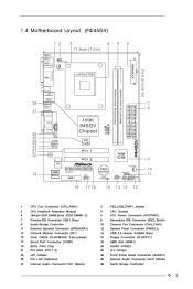
1.4 Motherboard Layout (P4i45GV) 1 2 3 4 17.8cm (7.0 in) 5 6 PS/2 Mouse 1 PS2_USB_PWR1 PARALLEL PORT Keyboard mPGA478B VGA LAN (optional) USB 2.0 Ports 28 USB 2.0 Ports DDR1 (64/72 bit, 184-...
1.4 Motherboard Layout (P4i45GV) 1 2 3 4 17.8cm (7.0 in) 5 6 PS/2 Mouse 1 PS2_USB_PWR1 PARALLEL PORT Keyboard mPGA478B VGA LAN (optional) USB 2.0 Ports 28 USB 2.0 Ports DDR1 (64/72 bit, 184-...
User Manual
Page 11
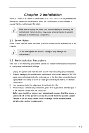
...do not touch the ICs. 4. Hold components by circles to secure the motherboard to use a grounded wrist strap or touch a safety grounded object before installing or removing the motherboard. Whenever you and damages to you uninstall any component. 2. Make sure to.... Also remember to the chassis. Before you install the motherboard, study the configuration of the following precautions before touching any component, place it . Before you install or remove any motherboard settings. 1. Chapter 2 Installation P4i45GL / P4i45GV is detached from the wall socket before you ...
...do not touch the ICs. 4. Hold components by circles to secure the motherboard to use a grounded wrist strap or touch a safety grounded object before installing or removing the motherboard. Whenever you and damages to you uninstall any component. 2. Make sure to.... Also remember to the chassis. Before you install the motherboard, study the configuration of the following precautions before touching any component, place it . Before you install or remove any motherboard settings. 1. Chapter 2 Installation P4i45GL / P4i45GV is detached from the wall socket before you ...
User Manual
Page 13
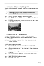
...you intend to insert an ASRock MR card (optional) with the slot and press firmly until the retaining clip snap back in a chassis). Step 2. Step 1. Align a DIMM on the slot such that the notch on the DIMM matches the break on P4i45GL / P4i45GV motherboard. Align the card connector... with v.92 Modem functionality. Step 2. Step 3. Before installing the expansion card, read the documentation of Memory Modules (DIMM) P4i45GL / P4i45GV motherboard provides two 184-pin DDR (Double Data Rate) DIMM slots. PCI slots: PCI slots are 2 PCI slots and 1 AMR slot on...
...you intend to insert an ASRock MR card (optional) with the slot and press firmly until the retaining clip snap back in a chassis). Step 2. Step 1. Align a DIMM on the slot such that the notch on the DIMM matches the break on P4i45GL / P4i45GV motherboard. Align the card connector... with v.92 Modem functionality. Step 2. Step 3. Before installing the expansion card, read the documentation of Memory Modules (DIMM) P4i45GL / P4i45GV motherboard provides two 184-pin DDR (Double Data Rate) DIMM slots. PCI slots: PCI slots are 2 PCI slots and 1 AMR slot on...

User Manual
Page 15
... connectors (4-pin CD1, 4-pin AUX1) (CD1: see p.8/p.9 item 27) (AUX1: see p.8/p.9 item 14) 1 GND P+4 P-4 USB_PWR USB_PWR P-5 P+5 GND DUMMY ASRock I/OTM provides 4 default USB 2.0 ports. If those USB 2.0 ports on the floppy ribbon cable with Pin1. 2.8 Connectors Connectors are not sufficient, this BLUE end ...to the motherboard 80-Pin ATA 100 cable Note: To optimize compatibility and performance, please connect your hard disk drive to the primary IDE connector (IDE1...
... connectors (4-pin CD1, 4-pin AUX1) (CD1: see p.8/p.9 item 27) (AUX1: see p.8/p.9 item 14) 1 GND P+4 P-4 USB_PWR USB_PWR P-5 P+5 GND DUMMY ASRock I/OTM provides 4 default USB 2.0 ports. If those USB 2.0 ports on the floppy ribbon cable with Pin1. 2.8 Connectors Connectors are not sufficient, this BLUE end ...to the motherboard 80-Pin ATA 100 cable Note: To optimize compatibility and performance, please connect your hard disk drive to the primary IDE connector (IDE1...
User Manual
Page 17
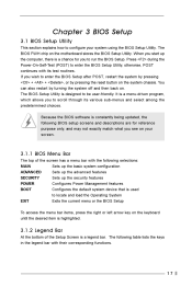
... System EXIT Exits the current menu or the BIOS Setup To access the menu bar items, press the right or left arrow key on the motherboard stores the BIOS Setup Utility. You can also restart by pressing the reset button on . The following BIOS setup screens and descriptions are for you...
... System EXIT Exits the current menu or the BIOS Setup To access the menu bar items, press the right or left arrow key on the motherboard stores the BIOS Setup Utility. You can also restart by pressing the reset button on . The following BIOS setup screens and descriptions are for you...

User Manual
Page 21
...chapter for more about ASRock, welcome to know more information. 4.2 Support CD Information The Support CD that came with the motherboard contains necessary drivers and useful utilities that the motherboard supports. Chapter 4 Software Support 4.1 Install Operating System This motherboard supports various Microsoft®...ROM drive. Refer to activate the devices. 4.2.3 Utilities Menu The Utilities Menu shows the applications software that enhance the motherboard features. 4.2.1 Running The Support CD To begin using the support CD, insert the CD into your computer. Please ...
...chapter for more about ASRock, welcome to know more information. 4.2 Support CD Information The Support CD that came with the motherboard contains necessary drivers and useful utilities that the motherboard supports. Chapter 4 Software Support 4.1 Install Operating System This motherboard supports various Microsoft®...ROM drive. Refer to activate the devices. 4.2.3 Utilities Menu The Utilities Menu shows the applications software that enhance the motherboard features. 4.2.1 Running The Support CD To begin using the support CD, insert the CD into your computer. Please ...

User Manual
Page 22
...): To enable this technology, such as Microsoft® Windows® XP. Set to enable or disable the feature of the installed motherboard. This option will detect the memory module(s) inserted and assigns appropriate frequency automatically. VERSION 3.31a Boot Power Exit [ Spread Spectrum CPU...spectrum. SDRAM Frequency: If [Auto] is determined by the installed processor. Whether the option is open or locked is selected, the motherboard will be [Disabled] for this feature, it requires a computer system with an Intel Pentium®4 processor that supports Hyper-Threading technology...
...): To enable this technology, such as Microsoft® Windows® XP. Set to enable or disable the feature of the installed motherboard. This option will detect the memory module(s) inserted and assigns appropriate frequency automatically. VERSION 3.31a Boot Power Exit [ Spread Spectrum CPU...spectrum. SDRAM Frequency: If [Auto] is determined by the installed processor. Whether the option is open or locked is selected, the motherboard will be [Disabled] for this feature, it requires a computer system with an Intel Pentium®4 processor that supports Hyper-Threading technology...
User Manual
Page 25
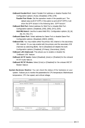
If this to monitor the parameters for CPU temperature, Motherboard temperature, CPU fan speed, and critical voltage. Configuration options: [3], [4], [5], [7], [10], [11]. OnBoard Game Port: Select address for the onboard AC'97 Audio feature. Or you ...
If this to monitor the parameters for CPU temperature, Motherboard temperature, CPU fan speed, and critical voltage. Configuration options: [3], [4], [5], [7], [10], [11]. OnBoard Game Port: Select address for the onboard AC'97 Audio feature. Or you ...

