User Manual
Page 3
... Contents 4 1.2 Specifications 5 1.3 Motherboard Layout (P4i45G 8 1.4 Motherboard Layout (P4i45GL 9 1.5 Motherboard Layout (P4i45GV 10 1.6 ASRock I/OTM (P4i45G / P4i45GL / P4i45GV 11 2 Installation 12 2.1 Screw Holes 12 2.2 Pre-installation Precautions 12 2.3 CPU Installation 12 2.4 Installation of Heatsink and CPU fan 13 2.5 Installation of Memory Modules (DIMM 13 2.6 Expansion Slots 14 2.7 Jumpers Setup 15 2.8 Connectors 16 3 BIOS Setup 18 3.1 BIOS Setup Utility 18 3.1.1 BIOS Menu Bar 18 3.1.2 Legend Bar 18 3.2 Main Menu 19 3.3 Advanced, Security, Power, Boot, and Exit...
... Contents 4 1.2 Specifications 5 1.3 Motherboard Layout (P4i45G 8 1.4 Motherboard Layout (P4i45GL 9 1.5 Motherboard Layout (P4i45GV 10 1.6 ASRock I/OTM (P4i45G / P4i45GL / P4i45GV 11 2 Installation 12 2.1 Screw Holes 12 2.2 Pre-installation Precautions 12 2.3 CPU Installation 12 2.4 Installation of Heatsink and CPU fan 13 2.5 Installation of Memory Modules (DIMM 13 2.6 Expansion Slots 14 2.7 Jumpers Setup 15 2.8 Connectors 16 3 BIOS Setup 18 3.1 BIOS Setup Utility 18 3.1.1 BIOS Menu Bar 18 3.1.2 Legend Bar 18 3.2 Main Menu 19 3.3 Advanced, Security, Power, Boot, and Exit...
User Manual
Page 5
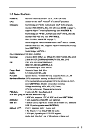
... floppy disk drive Audio: 5.1 channels AC'97 Audio PCI LAN: Speed: 802.3u (10/100 Ethernet), supports Wake-On-LAN Hardware Monitor: CPU temperature sensing (ASRock U-COP); CPU fan tachometer; North Bridge on P4i45G Motherboard): 1 AGP slot, supports 1.5V, 4X AGP card (see CAUTION 4) AMR slot: 1 slot, supports ASRock MR card (optional) USB 2.0: 4 default USB 2.0 ports and 1 extra set of header for SDR: DIMM3 and DIMM4 (PC133), Max. 2GB IDE: IDE1: ATA 100 / Ultra DMA Mode 5; Chassis temperature sensing; Chassis fan tachometer PCI slots: 3 slots with PCI Specification...
... floppy disk drive Audio: 5.1 channels AC'97 Audio PCI LAN: Speed: 802.3u (10/100 Ethernet), supports Wake-On-LAN Hardware Monitor: CPU temperature sensing (ASRock U-COP); CPU fan tachometer; North Bridge on P4i45G Motherboard): 1 AGP slot, supports 1.5V, 4X AGP card (see CAUTION 4) AMR slot: 1 slot, supports ASRock MR card (optional) USB 2.0: 4 default USB 2.0 ports and 1 extra set of header for SDR: DIMM3 and DIMM4 (PC133), Max. 2GB IDE: IDE1: ATA 100 / Ultra DMA Mode 5; Chassis temperature sensing; Chassis fan tachometer PCI slots: 3 slots with PCI Specification...
User Manual
Page 6
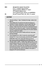
... also be overclocked proportionally. Please refer to perform over clocking, other than the recommended CPU bus frequencies may not work properly under Microsoft® Windows® XP. Although P4i45G / P4i45GL / P4i45GV offers stepless control, it will only support DDR 266. 3. Supports "Plug and Play"; Do NOT use 3.3V AGP card on the motherboard functions properly before you install the PC system. 4. Supports jumperfree; If the installed CPU runs with...
... also be overclocked proportionally. Please refer to perform over clocking, other than the recommended CPU bus frequencies may not work properly under Microsoft® Windows® XP. Although P4i45G / P4i45GL / P4i45GV offers stepless control, it will only support DDR 266. 3. Supports "Plug and Play"; Do NOT use 3.3V AGP card on the motherboard functions properly before you install the PC system. 4. Supports jumperfree; If the installed CPU runs with...
User Manual
Page 8
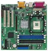
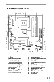
... IDE connector (IDE2, Black) 9 Chassis fan connector (CHA_FAN1) 10 Floppy connector (FLOPPY1) 11 BIOS FWH chip 12 System panel connector (PANEL1) 13 USB 2.0 header (USB45) 14 Infrared module connector (IR1) 15 External speaker connector (SPEAKER1) 16 South Bridge controller 17 Clear CMOS (CLRCMOS0, 2-pin jumper) 18 PCI slots (PCI 1- 3) 19 AUDIO CODEC 20 Front panel audio connector (AUDIO1) 21 PCI LAN 22 PS2_USB_PWR1 jumper 23 Internal audio connector: AUX1(white) 24 Internal audio connector: CD1 (black) 25 Serial port connector (COM1) 26 AMR slot (AMR1) 27 CPU heatsink retention...
... IDE connector (IDE2, Black) 9 Chassis fan connector (CHA_FAN1) 10 Floppy connector (FLOPPY1) 11 BIOS FWH chip 12 System panel connector (PANEL1) 13 USB 2.0 header (USB45) 14 Infrared module connector (IR1) 15 External speaker connector (SPEAKER1) 16 South Bridge controller 17 Clear CMOS (CLRCMOS0, 2-pin jumper) 18 PCI slots (PCI 1- 3) 19 AUDIO CODEC 20 Front panel audio connector (AUDIO1) 21 PCI LAN 22 PS2_USB_PWR1 jumper 23 Internal audio connector: AUX1(white) 24 Internal audio connector: CD1 (black) 25 Serial port connector (COM1) 26 AMR slot (AMR1) 27 CPU heatsink retention...

User Manual
Page 9
... IDE connector (IDE2, Black) 9 Chassis fan connector (CHA_FAN1) 10 Floppy connector (FLOPPY1) 11 BIOS FWH chip 12 System panel connector (PANEL1) 13 USB 2.0 header (USB45) 14 Infrared module connector (IR1) 15 External speaker connector (SPEAKER1) 16 South Bridge controller 17 Clear CMOS (CLRCMOS0, 2-pin jumper) 18 PCI slots (PCI 1- 3) 19 AUDIO CODEC 20 Front panel audio connector (AUDIO1) 21 PCI LAN 22 PS2_USB_PWR1 jumper 23 Internal audio connector: AUX1(white) 24 Internal audio connector: CD1 (black) 25 Serial port connector (COM1) 26 AMR slot (AMR1) 27 CPU heatsink retention...
... IDE connector (IDE2, Black) 9 Chassis fan connector (CHA_FAN1) 10 Floppy connector (FLOPPY1) 11 BIOS FWH chip 12 System panel connector (PANEL1) 13 USB 2.0 header (USB45) 14 Infrared module connector (IR1) 15 External speaker connector (SPEAKER1) 16 South Bridge controller 17 Clear CMOS (CLRCMOS0, 2-pin jumper) 18 PCI slots (PCI 1- 3) 19 AUDIO CODEC 20 Front panel audio connector (AUDIO1) 21 PCI LAN 22 PS2_USB_PWR1 jumper 23 Internal audio connector: AUX1(white) 24 Internal audio connector: CD1 (black) 25 Serial port connector (COM1) 26 AMR slot (AMR1) 27 CPU heatsink retention...

User Manual
Page 10
... IDE connector (IDE2, Black) 9 Chassis fan connector (CHA_FAN1) 10 Floppy connector (FLOPPY1) 11 BIOS FWH chip 12 System panel connector (PANEL1) 13 USB 2.0 header (USB45) 14 Infrared module connector (IR1) 15 External speaker connector (SPEAKER1) 16 South Bridge controller 17 Clear CMOS (CLRCMOS0, 2-pin jumper) 18 PCI slots (PCI 1- 3) 19 AUDIO CODEC 20 Front panel audio connector (AUDIO1) 21 PCI LAN 22 PS2_USB_PWR1 jumper 23 Internal audio connector: AUX1(white) 24 Internal audio connector: CD1 (black) 25 Serial port connector (COM1) 26 AMR slot (AMR1) 27 CPU heatsink retention...
... IDE connector (IDE2, Black) 9 Chassis fan connector (CHA_FAN1) 10 Floppy connector (FLOPPY1) 11 BIOS FWH chip 12 System panel connector (PANEL1) 13 USB 2.0 header (USB45) 14 Infrared module connector (IR1) 15 External speaker connector (SPEAKER1) 16 South Bridge controller 17 Clear CMOS (CLRCMOS0, 2-pin jumper) 18 PCI slots (PCI 1- 3) 19 AUDIO CODEC 20 Front panel audio connector (AUDIO1) 21 PCI LAN 22 PS2_USB_PWR1 jumper 23 Internal audio connector: AUX1(white) 24 Internal audio connector: CD1 (black) 25 Serial port connector (COM1) 26 AMR slot (AMR1) 27 CPU heatsink retention...
User Manual
Page 12
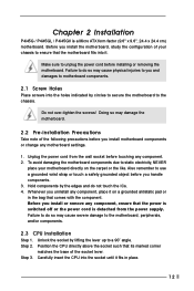
... power cord from the power supply. Unlock the socket by lifting the lever up to unplug the power cord before touching any motherboard settings. 1. Step 3. Before you install or remove any component, place it fits in the bag that the power is switched off or the power cord is a Micro ATX form factor (9.6" x 9.6", 24.4 x 24.4 cm) motherboard. Before you install the motherboard, study the configuration of the socket...
... power cord from the power supply. Unlock the socket by lifting the lever up to unplug the power cord before touching any motherboard settings. 1. Step 3. Before you install or remove any component, place it fits in the bag that the power is switched off or the power cord is a Micro ATX form factor (9.6" x 9.6", 24.4 x 24.4 cm) motherboard. Before you install the motherboard, study the configuration of the socket...
User Manual
Page 13
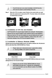
... Please do not use two different models of the pins. The lever clicks on the socket while you push down the socket lever to improve heat dissipation. For proper installation, please kindly refer to disconnect power supply before adding or removing DIMMs or the system components. 168-pin RAM 184-pin RAM The 168-pin SDRAM DIMM slot (black) and 184-pin DDR DIMM slot (blue) can...
... Please do not use two different models of the pins. The lever clicks on the socket while you push down the socket lever to improve heat dissipation. For proper installation, please kindly refer to disconnect power supply before adding or removing DIMMs or the system components. 168-pin RAM 184-pin RAM The 168-pin SDRAM DIMM slot (black) and 184-pin DDR DIMM slot (blue) can...
User Manual
Page 18
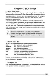
Because the BIOS software is constantly being updated, the following BIOS setup screens and descriptions are for you start up the security features POWER Configures Power Management features BOOT Configures the default system device that is designed to enter the BIOS Setup Utility, otherwise, POST continues with their corresponding functions. 18 When you to locate and load the Operating System EXIT Exits the current menu or the BIOS Setup To access the menu bar items, press the...
Because the BIOS software is constantly being updated, the following BIOS setup screens and descriptions are for you start up the security features POWER Configures Power Management features BOOT Configures the default system device that is designed to enter the BIOS Setup Utility, otherwise, POST continues with their corresponding functions. 18 When you to locate and load the Operating System EXIT Exits the current menu or the BIOS Setup To access the menu bar items, press the...
User Manual
Page 19
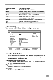
... Enter:Select Sub-Menu F9:Setup Defaults F10:Save & Exit System Date [Month/Day/Year] Set the system date that you specify. Use keys to move between the Hour, Minute and Second fields. IDE Devices Use this to configure IDE devices. 19 VERSION 3.31a Security Power Boot Exit Jan 08 2003 Wed 20:07:40 [ Setup Help ] Month: Jan - Main Advanced System Date System Time Floppy Drives IDE Devices BIOS Version Processor Type Processor Speed Cache Size Microcode Update Total Memory...
... Enter:Select Sub-Menu F9:Setup Defaults F10:Save & Exit System Date [Month/Day/Year] Set the system date that you specify. Use keys to move between the Hour, Minute and Second fields. IDE Devices Use this to configure IDE devices. 19 VERSION 3.31a Security Power Boot Exit Jan 08 2003 Wed 20:07:40 [ Setup Help ] Month: Jan - Main Advanced System Date System Time Floppy Drives IDE Devices BIOS Version Processor Type Processor Speed Cache Size Microcode Update Total Memory...
User Manual
Page 20
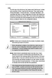
... display the size of the Primary IDE hard disk drives to get into BIOS, use a disk utility, such as FDISK, to automatically detect hard disk drive. After making your selections on Main menu and press to active. 20 If the autodetection fails, it may due to set the parameters of the IDE device, first, please select "IDE Devices" on this sub-menu. Make sure to that you have the correct configuration information supplied...
... display the size of the Primary IDE hard disk drives to get into BIOS, use a disk utility, such as FDISK, to automatically detect hard disk drive. After making your selections on Main menu and press to active. 20 If the autodetection fails, it may due to set the parameters of the IDE device, first, please select "IDE Devices" on this sub-menu. Make sure to that you have the correct configuration information supplied...
User Manual
Page 21
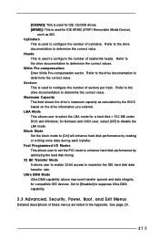
... value. Block Mode Set the block mode to [On] will enhance hard disk performance by optimizing the hard disk timing. 32 Bit Transfer Mode It allows user to enable 32-bit access to configure the number of sectors per track. [CD/DVD]: This is used for IDE CD/DVD drives. [ARMD]: This is used for IDE ARMD (ATAPI Removable Media Device), such as calculated by the BIOS based on the drive information you entered. Refer to...
... value. Block Mode Set the block mode to [On] will enhance hard disk performance by optimizing the hard disk timing. 32 Bit Transfer Mode It allows user to enable 32-bit access to configure the number of sectors per track. [CD/DVD]: This is used for IDE CD/DVD drives. [ARMD]: This is used for IDE ARMD (ATAPI Removable Media Device), such as calculated by the BIOS based on the drive information you entered. Refer to...

User Manual
Page 22
.... 4.2.2 Drivers Menu The Drivers Menu shows the available devices drivers if the system detects installed devices. Because motherboard settings and hardware options vary, use the setup procedures in your own PC system step by step. The CD automatically displays the Main Menu if "AUTORUN" is enabled in this demo program, you can run Microsoft Media Player to play the file. 4.2.5 Contact Information If you need to contact ASRock or...
.... 4.2.2 Drivers Menu The Drivers Menu shows the available devices drivers if the system detects installed devices. Because motherboard settings and hardware options vary, use the setup procedures in your own PC system step by step. The CD automatically displays the Main Menu if "AUTORUN" is enabled in this demo program, you can run Microsoft Media Player to play the file. 4.2.5 Contact Information If you need to contact ASRock or...
User Manual
Page 23
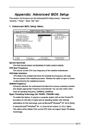
... the memory module(s) inserted and assigns appropriate frequency automatically. VERSION 3.31a Security Power Boot Exit Spread Spectrum CPU Host Frequency Actual Frequency CPU Ratio Selection SDRAM Frequency Hyper Threading Technology Disabled Disabled 133MHz Locked Auto Auto [ Setup Help ] to [Auto] if using Microsoft® Windows® XP, or Linux kernel version 2.4.18 or higher. Chipset Configuration Resource Configuration Peripheral Configuration System Hardware Monitor F1:Help Esc:Exit :Select Item :Select Menu +/-:Change Values Enter:Select Sub-Menu F9:Setup Defaults F10...
... the memory module(s) inserted and assigns appropriate frequency automatically. VERSION 3.31a Security Power Boot Exit Spread Spectrum CPU Host Frequency Actual Frequency CPU Ratio Selection SDRAM Frequency Hyper Threading Technology Disabled Disabled 133MHz Locked Auto Auto [ Setup Help ] to [Auto] if using Microsoft® Windows® XP, or Linux kernel version 2.4.18 or higher. Chipset Configuration Resource Configuration Peripheral Configuration System Hardware Monitor F1:Help Esc:Exit :Select Item :Select Menu +/-:Change Values Enter:Select Sub-Menu F9:Setup Defaults F10...
User Manual
Page 24
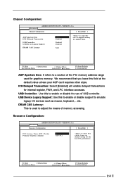
... to select the size of memory accessing. etc. DRAM CAS Latency: This is used for graphics data. F1:Help Esc:Previous Menu :Select Item +/-:Change Values Enter:Select Sub-Menu F9:Setup Defaults F10:Save & Exit 24 Chipset Configuration: Advanced AMIBIOS SETUP UTILITY - VERSION 3.31a Chipset Configuration [ Setup Help ] AGP Aperture Size ICH Delayed Transaction USB Controller USB Device Legacy Support DRAM CAS Latency 32MB Disabled Disabled Disabled Auto to adjust the means of mapped memory for graphics memory. Leave on default setting for internal register, FWH...
... to select the size of memory accessing. etc. DRAM CAS Latency: This is used for graphics data. F1:Help Esc:Previous Menu :Select Item +/-:Change Values Enter:Select Sub-Menu F9:Setup Defaults F10:Save & Exit 24 Chipset Configuration: Advanced AMIBIOS SETUP UTILITY - VERSION 3.31a Chipset Configuration [ Setup Help ] AGP Aperture Size ICH Delayed Transaction USB Controller USB Device Legacy Support DRAM CAS Latency 32MB Disabled Disabled Disabled Auto to adjust the means of mapped memory for graphics memory. Leave on default setting for internal register, FWH...
User Manual
Page 25
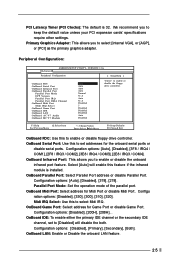
...select [Internal VGA], or [AGP], or [PCI] as the primary graphics adapter. OnBoard Midi Port: Select address for Game Port or disable Game Port. Peripheral Configuration: Advanced AMIBIOS SETUP UTILITY - F1:Help Esc:Previous Menu :Select Item +/-:Change Values Enter:Select Sub-Menu F9:Setup Defaults F10:Save & Exit OnBoard FDC: Use this to set addresses for the onboard serial ports or disable serial ports. OnBoard LAN: Enable or Disable the onboard LAN feature. 25 We recommend you to enable or disable the floppy drive controller. Configuration options: [Disabled], [Primary...
...select [Internal VGA], or [AGP], or [PCI] as the primary graphics adapter. OnBoard Midi Port: Select address for Game Port or disable Game Port. Peripheral Configuration: Advanced AMIBIOS SETUP UTILITY - F1:Help Esc:Previous Menu :Select Item +/-:Change Values Enter:Select Sub-Menu F9:Setup Defaults F10:Save & Exit OnBoard FDC: Use this to set addresses for the onboard serial ports or disable serial ports. OnBoard LAN: Enable or Disable the onboard LAN feature. 25 We recommend you to enable or disable the floppy drive controller. Configuration options: [Disabled], [Primary...
User Manual
Page 26
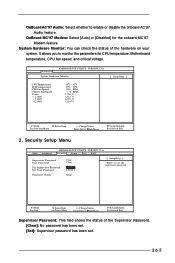
.... VERSION 3.31a System Hardware Monitor [ Setup Help ] CPU Temperature M/B Temperature CPU Fan Speed Chassis Fan Speed Vcore + 3.30V + 5.00V +12.00V 35 C / 95 F 27 C / 82 F 3110 RPM 0 RPM 1.728 V 3.312 V 4.975 V 12.167 V F1:Help Esc:Previous Menu :Select Item +/-:Change Values Enter:Select Sub-Menu F9:Setup Defaults F10:Save & Exit 2. Advanced AMIBIOS SETUP UTILITY - Security Setup Menu Main Advanced AMIBIOS SETUP UTILITY - System Hardware Monitor: You can check the status of the Supervisor Password. [Clear]: No password...
.... VERSION 3.31a System Hardware Monitor [ Setup Help ] CPU Temperature M/B Temperature CPU Fan Speed Chassis Fan Speed Vcore + 3.30V + 5.00V +12.00V 35 C / 95 F 27 C / 82 F 3110 RPM 0 RPM 1.728 V 3.312 V 4.975 V 12.167 V F1:Help Esc:Previous Menu :Select Item +/-:Change Values Enter:Select Sub-Menu F9:Setup Defaults F10:Save & Exit 2. Advanced AMIBIOS SETUP UTILITY - Security Setup Menu Main Advanced AMIBIOS SETUP UTILITY - System Hardware Monitor: You can check the status of the Supervisor Password. [Clear]: No password...
User Manual
Page 27
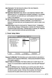
... Disabled Disabled Power Off Disabled Disabled Disabled Disabled Every Day 00 00 00 [ Setup Help ] Set the power state after an unexpected AC/power loss. F1:Help Esc:Exit :Select Item :Select Menu +/-:Change Values Enter:Select Sub-Menu F9:Setup Defaults F10:Save & Exit Suspend To RAM (S3): This field allows you to set User Password. Configuration options: [Setup], [Always]. Set Supervisor Password: Press to set . Valid password can be a 1 to enable this feature if the system supports it. Power Setup Menu Main...
... Disabled Disabled Power Off Disabled Disabled Disabled Disabled Every Day 00 00 00 [ Setup Help ] Set the power state after an unexpected AC/power loss. F1:Help Esc:Exit :Select Item :Select Menu +/-:Change Values Enter:Select Sub-Menu F9:Setup Defaults F10:Save & Exit Suspend To RAM (S3): This field allows you to set User Password. Configuration options: [Setup], [Always]. Set Supervisor Password: Press to set . Valid password can be a 1 to enable this feature if the system supports it. Power Setup Menu Main...
User Manual
Page 28
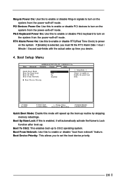
... Menu +/-:Change Values Enter:Select Sub-Menu F9:Setup Defaults F10:Save & Exit Quick Boot Mode: Enable this mode will automatically activate the Numeric Lock function after boot-up time you to set the boot device priority. 28 Boot Device Priority: This allows you desire. 4. Boot Setup Menu Main Advanced AMIBIOS SETUP UTILITY - If [Enable] is enabled, it will speed up the boot-up to OS/2 operating system. Boot From Network: Use this to enable or disable the quick boot mode. PS/2 Keyboard Power On: Use...
... Menu +/-:Change Values Enter:Select Sub-Menu F9:Setup Defaults F10:Save & Exit Quick Boot Mode: Enable this mode will automatically activate the Numeric Lock function after boot-up time you to set the boot device priority. 28 Boot Device Priority: This allows you desire. 4. Boot Setup Menu Main Advanced AMIBIOS SETUP UTILITY - If [Enable] is enabled, it will speed up the boot-up to OS/2 operating system. Boot From Network: Use this to enable or disable the quick boot mode. PS/2 Keyboard Power On: Use...
User Manual
Page 29
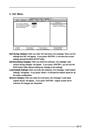
... enter the submenu, the message "Load Default Settings" will appear. 5. If you enter the submenu, the message "Quit without making any changes to the settings. Exit Discarding Changes: After you press , it will be restored. If you press , it will appear. Exit Menu Main Advanced AMIBIOS SETUP UTILITY - VERSION 3.31a Security Power Boot Exit Exit Saving Changes Exit Discarding Changes Load Default Settings Discard Changes [ Enter ] [ Enter ] [ Enter ] [ Enter ] [ Setup Help ] Exits and saves the changes in CMOS RAM...
... enter the submenu, the message "Load Default Settings" will appear. 5. If you enter the submenu, the message "Quit without making any changes to the settings. Exit Discarding Changes: After you press , it will be restored. If you press , it will appear. Exit Menu Main Advanced AMIBIOS SETUP UTILITY - VERSION 3.31a Security Power Boot Exit Exit Saving Changes Exit Discarding Changes Load Default Settings Discard Changes [ Enter ] [ Enter ] [ Enter ] [ Enter ] [ Setup Help ] Exits and saves the changes in CMOS RAM...


