
User Manual
Page 3
...Menu 22 2. Security Menu 26 3. Exit Menu 29 3 Contents 1 Introduction 4 1.1 Package Contents 4 1.2 Specifications 5 1.3 Motherboard Layout 8 1.4 ASRock I/OTM 9 2 Installation 10 2.1 Screw Holes 10 2.2 Pre-installation Precautions 10 2.3 CPU Installation 11 2.4 Installation of Heatsink and CPU fan 11 ...2.5 Installation of Memory Modules (DIMM 12 2.6 Expansion Slots 12 2.7 Jumpers Setup 14 2.8 Connectors 15 3 BIOS Setup 17 3.1 BIOS Setup Utility 17 3.1.1 BIOS Menu Bar 17 3.1.2 Legend Bar 17 3.2 Main Menu 18 3.3 Advanced, Security, Power, Boot, and Exit Menus .........
...Menu 22 2. Security Menu 26 3. Exit Menu 29 3 Contents 1 Introduction 4 1.1 Package Contents 4 1.2 Specifications 5 1.3 Motherboard Layout 8 1.4 ASRock I/OTM 9 2 Installation 10 2.1 Screw Holes 10 2.2 Pre-installation Precautions 10 2.3 CPU Installation 11 2.4 Installation of Heatsink and CPU fan 11 ...2.5 Installation of Memory Modules (DIMM 12 2.6 Expansion Slots 12 2.7 Jumpers Setup 14 2.8 Connectors 15 3 BIOS Setup 17 3.1 BIOS Setup Utility 17 3.1.1 BIOS Menu Bar 17 3.1.2 Legend Bar 17 3.2 Main Menu 18 3.3 Advanced, Security, Power, Boot, and Exit Menus .........

User Manual
Page 4
... 1 cable for IDE devices (1 x ATA 66 / 100) 1 cable for purchasing ASRock P4i45D+ motherboard, a reliable motherboard produced under ASRock's consistently stringent quality control. In case any modifications of the motherboard and step-bystep installation guide for new DIY system builders. Chapter 3 and 4 contain basic BIOS setup and support CD information. It delivers excellent performance with...
... 1 cable for IDE devices (1 x ATA 66 / 100) 1 cable for purchasing ASRock P4i45D+ motherboard, a reliable motherboard produced under ASRock's consistently stringent quality control. In case any modifications of the motherboard and step-bystep installation guide for new DIY system builders. Chapter 3 and 4 contain basic BIOS setup and support CD information. It delivers excellent performance with...

User Manual
Page 6
... 1. Please refer to spray thermal grease between the CPU and the heatsink when you resume the system. When the CPU frequency of P4i45D+ is set to perform over clocking. CPU FSB Frequency 800 533 400 Memory Support Frequency DDR400* DDR266 DDR266 *Please refer to perform... over clocking, it is detected, the system will also be overclocked proportionally. Although P4i45D+ offers stepless control, it 's Memory clock will automatically shutdown Vcore. BIOS: OS: AMI legal BIOS; While CPU overheat is not recommended to the NOTE on page 7 for USB 2.0 works ...
... 1. Please refer to spray thermal grease between the CPU and the heatsink when you resume the system. When the CPU frequency of P4i45D+ is set to perform over clocking. CPU FSB Frequency 800 533 400 Memory Support Frequency DDR400* DDR266 DDR266 *Please refer to perform... over clocking, it is detected, the system will also be overclocked proportionally. Although P4i45D+ offers stepless control, it 's Memory clock will automatically shutdown Vcore. BIOS: OS: AMI legal BIOS; While CPU overheat is not recommended to the NOTE on page 7 for USB 2.0 works ...

User Manual
Page 8
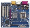
...845D Chipsets 8 9 Prescott 800 01 23 CMOS Battery AGP1 10 CLRCMOS0 11 PCI 1 21 PCI LAN P4i45D+ Intel 12 ICH2 20 Super I/O PCI 2 PCI 3 USB45 1 13 FSB 800 DDR400 14 2MB 19 BIOS PCI 4 FLOPPY1 PANEL 1 USB2.0 5.1CH 1 IR1 CHA_FAN1 PLED PWRBTN SPEAKER1 1 1 HDLED RST 18...(IDE2, Black) 11 AGP slot (AGP1) 13 USB 2.0 header (USB45, Blue) 15 System panel connector (PANEL1) 17 Chassis fan connector (CHA_FAN1) 19 BIOS FWH chip 21 PCI LAN 23 JL1 jumper 25 Front panel audio connector (AUDIO1) 27 Internal audio connector: CD1 (Black) 8 2 CPU fan connector (CPU_FAN1...
...845D Chipsets 8 9 Prescott 800 01 23 CMOS Battery AGP1 10 CLRCMOS0 11 PCI 1 21 PCI LAN P4i45D+ Intel 12 ICH2 20 Super I/O PCI 2 PCI 3 USB45 1 13 FSB 800 DDR400 14 2MB 19 BIOS PCI 4 FLOPPY1 PANEL 1 USB2.0 5.1CH 1 IR1 CHA_FAN1 PLED PWRBTN SPEAKER1 1 1 HDLED RST 18...(IDE2, Black) 11 AGP slot (AGP1) 13 USB 2.0 header (USB45, Blue) 15 System panel connector (PANEL1) 17 Chassis fan connector (CHA_FAN1) 19 BIOS FWH chip 21 PCI LAN 23 JL1 jumper 25 Front panel audio connector (AUDIO1) 27 Internal audio connector: CD1 (Black) 8 2 CPU fan connector (CPU_FAN1...

User Manual
Page 17
...for reference purpose only, and may not exactly match what you to locate and load the Operating System EXIT Exits the current menu or the BIOS Setup To access the menu bar items, press the right or left arrow key on the keyboard until the desired item is highlighted. 3.1.2 ...features POWER Configures Power Management features BOOT Configures the default system device that is a legend bar. You may run the BIOS Setup when you wish to configure your screen. 3.1.1 BIOS Menu Bar The top of the Setup Screen is used to scroll through its test routines. You may also restart ...
...for reference purpose only, and may not exactly match what you to locate and load the Operating System EXIT Exits the current menu or the BIOS Setup To access the menu bar items, press the right or left arrow key on the keyboard until the desired item is highlighted. 3.1.2 ...features POWER Configures Power Management features BOOT Configures the default system device that is a legend bar. You may run the BIOS Setup when you wish to configure your screen. 3.1.1 BIOS Menu Bar The top of the Setup Screen is used to scroll through its test routines. You may also restart ...

User Manual
Page 18
Dec Day: 01 - 31 Year: 1980 - 2099 P4i45D+ BIOS P1.00 Pentium(R) 4 CPU 2400 MHz 512 KB F24 / 18 128 MB 128 MB / 133 MHz (DDR266) None F1:Help Esc:Exit :Select Item :Select ... you specify. System Time [Hour:Minute:Second] Set the system to the time that you enter the BIOS Setup Utility, the following screen appears. Main Advanced System Date System Time Floppy Drives IDE Devices BIOS Version Processor Type Processor Speed Cache Size Microcode Update Total Memory DDR1 DDR2 AMIBIOS SETUP UTILITY - Navigation...
Dec Day: 01 - 31 Year: 1980 - 2099 P4i45D+ BIOS P1.00 Pentium(R) 4 CPU 2400 MHz 512 KB F24 / 18 128 MB 128 MB / 133 MHz (DDR266) None F1:Help Esc:Exit :Select Item :Select ... you specify. System Time [Hour:Minute:Second] Set the system to the time that you enter the BIOS Setup Utility, the following screen appears. Main Advanced System Date System Time Floppy Drives IDE Devices BIOS Version Processor Type Processor Speed Cache Size Microcode Update Total Memory DDR1 DDR2 AMIBIOS SETUP UTILITY - Navigation...

User Manual
Page 19
.... 19 In these cases, select [User] to automatically detect hard disk drive. This is necessary so that the hard disk is successful, the BIOS Setup automatically fills in the correct values for the drive. Before attempting to configure a hard disk drive, make configuration of cylinders, heads, and... among "Primary IDE Master", "Primary IDE Slave", "Secondary IDE Master", and "Secondary IDE Slave" to make sure you can write the data into BIOS, use a disk utility, such as FDISK, to manually enter the number of its type. Main AMIBIOS SETUP UTILITY - After entering the hard disk ...
.... 19 In these cases, select [User] to automatically detect hard disk drive. This is necessary so that the hard disk is successful, the BIOS Setup automatically fills in the correct values for the drive. Before attempting to configure a hard disk drive, make configuration of cylinders, heads, and... among "Primary IDE Master", "Primary IDE Slave", "Secondary IDE Master", and "Secondary IDE Slave" to make sure you can write the data into BIOS, use a disk utility, such as FDISK, to manually enter the number of its type. Main AMIBIOS SETUP UTILITY - After entering the hard disk ...

User Manual
Page 20
... the IDE hard disk data transfer rate. Fast Programmed I/O Modes This allows user to set the PIO mode to enhance hard disk performance by the BIOS based on the drive information you entered. [CD/DVD]: This is used for IDE CD/DVD drives. [ARMD]: This is used to configure the number...
... the IDE hard disk data transfer rate. Fast Programmed I/O Modes This allows user to set the PIO mode to enhance hard disk performance by the BIOS based on the drive information you entered. [CD/DVD]: This is used for IDE CD/DVD drives. [ARMD]: This is used to configure the number...
User Manual
Page 22
... Intel Pentium®4 processor at 3.06 GHz or higher and an operating system that times the frontside bus frequency will introduce you the following BIOS Setup menus: "Advanced," "Security," "Power," "Boot," and "Exit." 1. Flexibility Option The default value of the installed motherboard. CPU ...Host Frequency: This shows current CPU host frequency of this technology, such as Microsoft® Windows® XP. Advanced BIOS Setup Menu Main Advanced AMIBIOS SETUP UTILITY - Whether the option is open or locked is [Disabled]. VERSION 3.31a Security Power Boot ...
... Intel Pentium®4 processor at 3.06 GHz or higher and an operating system that times the frontside bus frequency will introduce you the following BIOS Setup menus: "Advanced," "Security," "Power," "Boot," and "Exit." 1. Flexibility Option The default value of the installed motherboard. CPU ...Host Frequency: This shows current CPU host frequency of this technology, such as Microsoft® Windows® XP. Advanced BIOS Setup Menu Main Advanced AMIBIOS SETUP UTILITY - Whether the option is open or locked is [Disabled]. VERSION 3.31a Security Power Boot ...

User Manual
Page 26
... No password has been set. [Set]: User password has been set . If [Setup] option is selected, the "Password Check" is performed before BIOS setup. User Password: This field shows the status of the Supervisor Password. [Clear]: No password has been set. [Set]: Supervisor password has been ...User Password: Press to create a new password. If [Always] option is selected, the "Password Check" is performed before both boot-up and BIOS setup. 26 If you already have a password, you need to enter your current password first in order to set the Supervisor Password. 2. Security...
... No password has been set. [Set]: User password has been set . If [Setup] option is selected, the "Password Check" is performed before BIOS setup. User Password: This field shows the status of the Supervisor Password. [Clear]: No password has been set. [Set]: Supervisor password has been ...User Password: Press to create a new password. If [Always] option is selected, the "Password Check" is performed before both boot-up and BIOS setup. 26 If you already have a password, you need to enter your current password first in order to set the Supervisor Password. 2. Security...

User Manual
Page 29
... changes" will appear. If you press , you enter the sub-menu, the message "Load setup original values" will save the current settings and exit the BIOS SETUP Utility. VERSION 3.31a Security Power Boot Exit Exit Saving Changes Exit Discarding Changes Load Default Settings Discard Changes [ Enter ] [ Enter ] [ Enter ] [ Enter ] [ Setup Help...
... changes" will appear. If you press , you enter the sub-menu, the message "Load setup original values" will save the current settings and exit the BIOS SETUP Utility. VERSION 3.31a Security Power Boot Exit Exit Saving Changes Exit Discarding Changes Load Default Settings Discard Changes [ Enter ] [ Enter ] [ Enter ] [ Enter ] [ Setup Help...

User Manual
Page 3
... 23 3 Contents 1 Introduction 4 1.1 Package Contents 4 1.2 Specifications 4 1.3 Motherboard Layout 6 1.4 ASRock I/OTM 7 2 Installation 8 2.1 Screw Holes 8 2.2 Pre-installation Precautions 8 2.3 CPU Installation 8 2.4 Installation of Heatsink and CPU fan 9 2.5 Installation of Memory Modules (DIMM 9 2.6 Expansion Slots 10 2.7 Jumpers Setup 11 2.8 Connectors 11 3 BIOS Setup 14 3.1 BIOS Setup Utility 14 3.1.1 BIOS Menu Bar 14 3.1.2 Legend Bar 14 3.2 Main Menu 15...
... 23 3 Contents 1 Introduction 4 1.1 Package Contents 4 1.2 Specifications 4 1.3 Motherboard Layout 6 1.4 ASRock I/OTM 7 2 Installation 8 2.1 Screw Holes 8 2.2 Pre-installation Precautions 8 2.3 CPU Installation 8 2.4 Installation of Heatsink and CPU fan 9 2.5 Installation of Memory Modules (DIMM 9 2.6 Expansion Slots 10 2.7 Jumpers Setup 11 2.8 Connectors 11 3 BIOS Setup 14 3.1 BIOS Setup Utility 14 3.1.1 BIOS Menu Bar 14 3.1.2 Legend Bar 14 3.2 Main Menu 15...

User Manual
Page 4
... reference, the Appendix offers more advanced BIOS setup information. 1.1 Package Contents ASRock P4I45D motherboard (ATX form factor: 12" x 9.6", 30.5 x 24.4 cm) ASRock P4I45D Quick Installation Guide ASRock Intel-Intel Series Support CD 1 Cable for IDE devices (1 x ATA 66/100) 1 Cable for floppy drive (1 x ribbon cable) 1 ASRock I/O shield 1.2 Specifications Platform: ATX ... - 200MHz Memory: 2 slots for DDR: DIMM1 and DIMM2 (PC1600/ PC2100), Max. 2GB; 2 slots for purchasing ASRock P4I45D motherboard, a reliable motherboard produced under ASRock's consistently stringent quality control.
... reference, the Appendix offers more advanced BIOS setup information. 1.1 Package Contents ASRock P4I45D motherboard (ATX form factor: 12" x 9.6", 30.5 x 24.4 cm) ASRock P4I45D Quick Installation Guide ASRock Intel-Intel Series Support CD 1 Cable for IDE devices (1 x ATA 66/100) 1 Cable for floppy drive (1 x ribbon cable) 1 ASRock I/O shield 1.2 Specifications Platform: ATX ... - 200MHz Memory: 2 slots for DDR: DIMM1 and DIMM2 (PC1600/ PC2100), Max. 2GB; 2 slots for purchasing ASRock P4I45D motherboard, a reliable motherboard produced under ASRock's consistently stringent quality control.

User Manual
Page 5
...174; 98 SE / ME / 2000 / XP compliant CAUTION! 1. Do NOT use the slot PCI 5 if there is USB device working on P4I45D's AGP slot! It may not work properly under Microsoft® Windows® XP. Frequencies other than the recommended CPU bus frequency may cause the instability...2.3.1 support; Legacy support is recommended to attach USB keyboard / mouse to the USB 1.1 ports: USB 2,3, see page 7 item 7. 5. AGP slot: USB 2.0: USB 1.1: ASRock I/OTM: BIOS: OS: 1 AGP slot, supports 1.5v, 4X / 2X / 1X AGP card (see CAUTION 3) 2 default USB 2.0 ports and one extra set of USB 2.0 header ...
...174; 98 SE / ME / 2000 / XP compliant CAUTION! 1. Do NOT use the slot PCI 5 if there is USB device working on P4I45D's AGP slot! It may not work properly under Microsoft® Windows® XP. Frequencies other than the recommended CPU bus frequency may cause the instability...2.3.1 support; Legacy support is recommended to attach USB keyboard / mouse to the USB 1.1 ports: USB 2,3, see page 7 item 7. 5. AGP slot: USB 2.0: USB 1.1: ASRock I/OTM: BIOS: OS: 1 AGP slot, supports 1.5v, 4X / 2X / 1X AGP card (see CAUTION 3) 2 default USB 2.0 ports and one extra set of USB 2.0 header ...

User Manual
Page 14
...-menus and select among the predetermined choices. Press during the Power-On-Self-Test (POST) to enter the BIOS Setup Utility, otherwise, POST continues with their corresponding functions. 14 The BIOS Setup Utility is designed to be user-friendly. It is a menu-driven program, which allows you to run...Management features BOOT Configures the default system device that is used to locate and load the Operating System EXIT Exits the current menu or the BIOS Setup To access the menu bar items, press the right or left arrow key on the keyboard until the desired item is highlighted. ...
...-menus and select among the predetermined choices. Press during the Power-On-Self-Test (POST) to enter the BIOS Setup Utility, otherwise, POST continues with their corresponding functions. 14 The BIOS Setup Utility is designed to be user-friendly. It is a menu-driven program, which allows you to run...Management features BOOT Configures the default system device that is used to locate and load the Operating System EXIT Exits the current menu or the BIOS Setup To access the menu bar items, press the right or left arrow key on the keyboard until the desired item is highlighted. ...

User Manual
Page 15
...UTILITY - Valid values for a highlighted field Resets the current screen to its Setup Defaults Saves changes and exits Setup 3.2 Main Menu When you enter the BIOS Setup Utility, the following screen appears. Use keys to move between the Hour, Minute and Second fields. Navigation Key(s) / / + / Function Description ...Help ] Month: Jan - System Time [Hour:Minute:Second] Set the system to configure IDE devices. 15 Dec Day: 01 - 31 Year: 1980 - 2099 P4I45D BIOS L1.00 Pentium (R) 4 Family CPU 2400 MHz 512 KB F24 / 0F 128 MB 128 MB / 266 MHz None None None F1:Help Esc:Exit :Select...
...UTILITY - Valid values for a highlighted field Resets the current screen to its Setup Defaults Saves changes and exits Setup 3.2 Main Menu When you enter the BIOS Setup Utility, the following screen appears. Use keys to move between the Hour, Minute and Second fields. Navigation Key(s) / / + / Function Description ...Help ] Month: Jan - System Time [Hour:Minute:Second] Set the system to configure IDE devices. 15 Dec Day: 01 - 31 Year: 1980 - 2099 P4I45D BIOS L1.00 Pentium (R) 4 Family CPU 2400 MHz 512 KB F24 / 0F 128 MB 128 MB / 266 MHz None None None F1:Help Esc:Exit :Select...
User Manual
Page 16
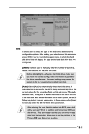
After making your selections on an older system, the BIOS Setup may detect incorrect parameters. If the autodetection fails, it may cause the.... Below are the configuration options. Incorrect settings may due to that the hard disk is successful, the BIOS Setup automatically fills in the correct values for the remaining fields on this sub-menu, press key to return...select the type of the Primary IDE hard disk drives to active. 16 After entering the hard disk information into BIOS, use a disk utility, such as FDISK, to manually enter the IDE hard disk drive parameters. If auto...
After making your selections on an older system, the BIOS Setup may detect incorrect parameters. If the autodetection fails, it may cause the.... Below are the configuration options. Incorrect settings may due to that the hard disk is successful, the BIOS Setup automatically fills in the correct values for the remaining fields on this sub-menu, press key to return...select the type of the Primary IDE hard disk drives to active. 16 After entering the hard disk information into BIOS, use a disk utility, such as FDISK, to manually enter the IDE hard disk drive parameters. If auto...

User Manual
Page 17
... number of sectors per track. Sectors This is used to determine the correct value. for IDE ARMD (Accelerated RemovableMedia Device), such as calculated by the BIOS based on the drive information you entered. Block Mode Set the block mode to [On] will enhance hard disk performance by optimizing the hard disk...
... number of sectors per track. Sectors This is used to determine the correct value. for IDE ARMD (Accelerated RemovableMedia Device), such as calculated by the BIOS based on the drive information you entered. Block Mode Set the block mode to [On] will enhance hard disk performance by optimizing the hard disk...

User Manual
Page 19
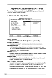
You can also select other value as Microsoft® Windows® XP. Appendix: Advanced BIOS Setup This section will introduce you the following BIOS Setup menus: "Advanced," "Security," "Power," "Boot," and "Exit." 1. CPU Host Frequency: [Auto]: The motherboard detects the... the motherboard detects the memory module(s) inserted and automatically assigns appropriate frequency. Wrong setup may cause problems during operation. Advanced BIOS Setup Menu Main Advanced AMIBIOS SETUP UTILITY - VERSION 3.31a Security Power Boot Exit Spread Spectrum CPU Host Frequency Actual Frequency ...
You can also select other value as Microsoft® Windows® XP. Appendix: Advanced BIOS Setup This section will introduce you the following BIOS Setup menus: "Advanced," "Security," "Power," "Boot," and "Exit." 1. CPU Host Frequency: [Auto]: The motherboard detects the... the motherboard detects the memory module(s) inserted and automatically assigns appropriate frequency. Wrong setup may cause problems during operation. Advanced BIOS Setup Menu Main Advanced AMIBIOS SETUP UTILITY - VERSION 3.31a Security Power Boot Exit Spread Spectrum CPU Host Frequency Actual Frequency ...

User Manual
Page 22
is performed before both boot-up and BIOS setup. 3. Power Setup Menu Suspend to RAM (S3): This field allows you must fill the RTC Alarm Date / Hour / Minute / Second sub-fields with the ... Time Clock) to turn on S3 resume. If [Enable] is recommended to -RAM feature. If [Always] option is selected, the "Password Check" is performed before BIOS setup. It is selected, you to select whether to auto-detect or disable the ACPI Suspend-to enable this feature if the system supports it.
is performed before both boot-up and BIOS setup. 3. Power Setup Menu Suspend to RAM (S3): This field allows you must fill the RTC Alarm Date / Hour / Minute / Second sub-fields with the ... Time Clock) to turn on S3 resume. If [Enable] is recommended to -RAM feature. If [Always] option is selected, the "Password Check" is performed before BIOS setup. It is selected, you to select whether to auto-detect or disable the ACPI Suspend-to enable this feature if the system supports it.


