User Manual
Page 3
Contents 1. Installation 10 Pre-installation Precautions 10 2.1 CPU Installation 11 2.2 Installation of CPU Fan and Heatsink 11 2.3 Installation of Memory Modules (DIMM 12 2.4 Expansion Slots (PCI, AMR, and AGP Slots 13 2.5 Jumpers Setup 14 2.6 Onboard Headers and Connectors 15 2.7 Serial ATA (SATA) Hard Disks ... Hardware Health Event Monitoring Screen 32 3.5 Boot Screen 32 3.5.1 Boot Settings Configuration 33 3.6 Security Screen 33 3.7 Exit Screen 34 3 Introduction 5 1.1 Package Contents 5 1.2 Specifications 6 1.3 Motherboard Layout 8 1.4 ASRock I/O Plus 9 TM 2.
Contents 1. Installation 10 Pre-installation Precautions 10 2.1 CPU Installation 11 2.2 Installation of CPU Fan and Heatsink 11 2.3 Installation of Memory Modules (DIMM 12 2.4 Expansion Slots (PCI, AMR, and AGP Slots 13 2.5 Jumpers Setup 14 2.6 Onboard Headers and Connectors 15 2.7 Serial ATA (SATA) Hard Disks ... Hardware Health Event Monitoring Screen 32 3.5 Boot Screen 32 3.5.1 Boot Settings Configuration 33 3.6 Security Screen 33 3.7 Exit Screen 34 3 Introduction 5 1.1 Package Contents 5 1.2 Specifications 6 1.3 Motherboard Layout 8 1.4 ASRock I/O Plus 9 TM 2.
User Manual
Page 5
... and information of the Support CD. Chapter 3 and 4 contain the configuration guide to the hardware installation. ASRock website http://www.asrock.com 1.1 Package Contents ASRock P4VM800 Motherboard (Micro ATX Form Factor: 9.6-in x 8.0-in Floppy Drive One Serial ATA (SATA) Cable One ...Serial ATA (SATA) HDD Power Cable(Optional) One ASRock I/O PlusTM Shield One COM Port Bracket 5 1. You may find the latest memory and CPU support lists on ASRock...
... and information of the Support CD. Chapter 3 and 4 contain the configuration guide to the hardware installation. ASRock website http://www.asrock.com 1.1 Package Contents ASRock P4VM800 Motherboard (Micro ATX Form Factor: 9.6-in x 8.0-in Floppy Drive One Serial ATA (SATA) Cable One ...Serial ATA (SATA) HDD Power Cable(Optional) One ASRock I/O PlusTM Shield One COM Port Bracket 5 1. You may find the latest memory and CPU support lists on ASRock...

User Manual
Page 6
...800/533/400 MHz, with Intel® Hyper-Threading Technology ready (see CAUTION 1) South Bridge: VIA VT8237R, supports USB 2.0, ATA 133, SATA 1.5Gb/s Memory: 2 DDR DIMM Slots: DDR1 and DDR2 1 DDR DIMM Slot Supports PC3200 (DDR400), Max. 1GB, 2 DDR DIMM Slots Supports PC2700 (DDR333) / ....3u (10/100 Ethernet), supports Wake-On-LAN Hardware Monitor: CPU temperature sensing Chassis temperature sensing CPU overheat shutdown to protect CPU life (ASRock U-COP)(see CAUTION 2) CPU fan tachometer Chassis fan tachometer Voltage monitoring: +12V, +5V, +3.3V, Vcore PCI slots: 3 slots with...
...800/533/400 MHz, with Intel® Hyper-Threading Technology ready (see CAUTION 1) South Bridge: VIA VT8237R, supports USB 2.0, ATA 133, SATA 1.5Gb/s Memory: 2 DDR DIMM Slots: DDR1 and DDR2 1 DDR DIMM Slot Supports PC3200 (DDR400), Max. 1GB, 2 DDR DIMM Slots Supports PC2700 (DDR333) / ....3u (10/100 Ethernet), supports Wake-On-LAN Hardware Monitor: CPU temperature sensing Chassis temperature sensing CPU overheat shutdown to protect CPU life (ASRock U-COP)(see CAUTION 2) CPU fan tachometer Chassis fan tachometer Voltage monitoring: +12V, +5V, +3.3V, Vcore PCI slots: 3 slots with...

User Manual
Page 8
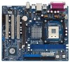
Blue) 6 Infrared Module Header (IR1) 7 Flash Memory 8 ATX Power Connector (ATXPWR1) 9 Floppy Connector (FLOPPY1) 10 Secondary IDE Connector (IDE2, Black) 11 Primary IDE Connector (IDE1, Blue) 12 AGP Slot (1.5V_AGP1) 13 South ... B: USB5 LAN PHY VIA P4M800 Chipset 5.1CH 1 AUDIO1 CMOS Battery JR1 JL1 CLRCMOS1 CD1 AUX1 Audio CODEC AMR1 AGP 8X 1.5V_AGP1 ATA133 IDE1 IDE2 PCI 1 ` P4VM800 PCI 2 USB2.0 PCI 3 1 COM1 VIA VT8237R SATA 1 USB67 PANEL 1 PLED PWRBTN 1 1 SPEAKER1 HDLED RESET SATA2 SATA1 Prescott 800 DDR400 DDR1 (64/72 bit, 184-pin...
Blue) 6 Infrared Module Header (IR1) 7 Flash Memory 8 ATX Power Connector (ATXPWR1) 9 Floppy Connector (FLOPPY1) 10 Secondary IDE Connector (IDE2, Black) 11 Primary IDE Connector (IDE1, Blue) 12 AGP Slot (1.5V_AGP1) 13 South ... B: USB5 LAN PHY VIA P4M800 Chipset 5.1CH 1 AUDIO1 CMOS Battery JR1 JL1 CLRCMOS1 CD1 AUX1 Audio CODEC AMR1 AGP 8X 1.5V_AGP1 ATA133 IDE1 IDE2 PCI 1 ` P4VM800 PCI 2 USB2.0 PCI 3 1 COM1 VIA VT8237R SATA 1 USB67 PANEL 1 PLED PWRBTN 1 1 SPEAKER1 HDLED RESET SATA2 SATA1 Prescott 800 DDR400 DDR1 (64/72 bit, 184-pin...

User Manual
Page 12
... DIMM is properly seated. 12 Firmly insert the DIMM into the slot at both ends fully snap back in one correct orientation. 2.3 Installation of Memory Modules (DIMM) P4VM800 motherboard provides two 184-pin DDR (Double Data Rate) DIMM slots. Step 2. Please make sure to the motherboard and the DIMM if you force...
... DIMM is properly seated. 12 Firmly insert the DIMM into the slot at both ends fully snap back in one correct orientation. 2.3 Installation of Memory Modules (DIMM) P4VM800 motherboard provides two 184-pin DDR (Double Data Rate) DIMM slots. Step 2. Please make sure to the motherboard and the DIMM if you force...

User Manual
Page 21
... bar, and then press to configure your screen. 3.1.1 BIOS Menu Bar The top of the screen has a menu bar with its test routines. The Flash Memory on . If you see on the system chassis. BIOS SETUP UTILITY 3.1 Introduction This section explains how to use the BIOS SETUP UTILITY to get into...
... bar, and then press to configure your screen. 3.1.1 BIOS Menu Bar The top of the screen has a menu bar with its test routines. The Flash Memory on . If you see on the system chassis. BIOS SETUP UTILITY 3.1 Introduction This section explains how to use the BIOS SETUP UTILITY to get into...

User Manual
Page 22
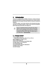
...Main Advanced H/W Monitor Boot Security Exit System Overview System Time System Date [17:00:09] [Fri 02/25/2005] BIOS Version : P4VM800 BIOS P1.00 Processor Type : Intel (R) Pentium (R) 4 CPU 2.40 GHz Processor Speed : 2400 MHz Cache Size : 512KB Microcode Update : 0F24/...1E Total Memory DIMM 1 DIMM 2 : 256MB with 64MB shared memory : 256MB/166MHz (DDR333) : None Use [Enter], [TAB] or [SHIFT-TAB] to the Exit Screen or exit the current screen 3.2 Main...
...Main Advanced H/W Monitor Boot Security Exit System Overview System Time System Date [17:00:09] [Fri 02/25/2005] BIOS Version : P4VM800 BIOS P1.00 Processor Type : Intel (R) Pentium (R) 4 CPU 2.40 GHz Processor Speed : 2400 MHz Cache Size : 512KB Microcode Update : 0F24/...1E Total Memory DIMM 1 DIMM 2 : 256MB with 64MB shared memory : 256MB/166MHz (DDR333) : None Use [Enter], [TAB] or [SHIFT-TAB] to the Exit Screen or exit the current screen 3.2 Main...
User Manual
Page 24
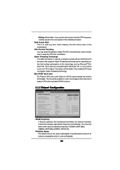
...(ex. Ratio Actual Value This is [Disabled]. DRAM Frequency If [Auto] is set to boot legacy OSes that includes optimization for memory compatibility when it will be enabled in order to [Enabled]. 24 Set to keep the CPU from overheated. Flexibility Option The default value... This should be equal to time the CPU frequency, it is selected, the motherboard will be hidden. This option will detect the memory module(s) inserted and assigns appropriate frequency automatically. CPU Thermal Throttling You may also select other value as Microsoft® Windows® XP....
...(ex. Ratio Actual Value This is [Disabled]. DRAM Frequency If [Auto] is set to boot legacy OSes that includes optimization for memory compatibility when it will be enabled in order to [Enabled]. 24 Set to keep the CPU from overheated. Flexibility Option The default value... This should be equal to time the CPU frequency, it is selected, the motherboard will be hidden. This option will detect the memory module(s) inserted and assigns appropriate frequency automatically. CPU Thermal Throttling You may also select other value as Microsoft® Windows® XP....
User Manual
Page 25
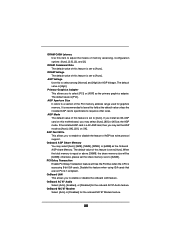
... of this feature is set to [Auto]. It is a 4X-AGP card, then you to select [PCI] or [AGP] as the Onboard AGP share Memory. PCI Delay Transaction Enable PCI Delay Transaction feature will be [64MB]; Configuration options: [Auto], [2.5], [2], and [3]. OnBoard MC'97 Modem Select [Auto] or... for the onboard AC'97 Audio feature. Disable this to enable or disable the onboard LAN feature. DRAM Command Rate The default value of memory accessing. AGP Voltage Use this feature when using ISA cards that are not PCI 2.1 compliant. Primary Graphics Adapter This allows you may select ...
... of this feature is set to [Auto]. It is a 4X-AGP card, then you to select [PCI] or [AGP] as the Onboard AGP share Memory. PCI Delay Transaction Enable PCI Delay Transaction feature will be [64MB]; Configuration options: [Auto], [2.5], [2], and [3]. OnBoard MC'97 Modem Select [Auto] or... for the onboard AC'97 Audio feature. Disable this to enable or disable the onboard LAN feature. DRAM Command Rate The default value of memory accessing. AGP Voltage Use this feature when using ISA cards that are not PCI 2.1 compliant. Primary Graphics Adapter This allows you may select ...

