User Manual
Page 3
...Jumpers Setup 14 2.6 Onboard Headers and Connectors 15 2.7 Serial ATA (SATA) Hard Disks Installation 18 2.8 Hot Plug and Hot Swap Functions for SATA HDDs ....... 18 2.9 Installing Windows 2000 / Windows XP With RAID Functions 19 2.10 Installing Windows 98 / ME / 2000 / XP Without RAID Functions 20 3. Contents 1. Introduction 5 1.1 Package Contents 5 1.2 Specifications 6 1.3 Motherboard Layout 8 1.4 ASRock I/O Plus 9 TM 2. BIOS SETUP UTILITY 21 3.1 Introduction 21 3.1.1 BIOS Menu Bar 21 3.1.2 Navigation Keys 22 3.2 Main Screen 22 3.3 Advanced Screen 22 3.3.1 CPU Configuration...
...Jumpers Setup 14 2.6 Onboard Headers and Connectors 15 2.7 Serial ATA (SATA) Hard Disks Installation 18 2.8 Hot Plug and Hot Swap Functions for SATA HDDs ....... 18 2.9 Installing Windows 2000 / Windows XP With RAID Functions 19 2.10 Installing Windows 98 / ME / 2000 / XP Without RAID Functions 20 3. Contents 1. Introduction 5 1.1 Package Contents 5 1.2 Specifications 6 1.3 Motherboard Layout 8 1.4 ASRock I/O Plus 9 TM 2. BIOS SETUP UTILITY 21 3.1 Introduction 21 3.1.1 BIOS Menu Bar 21 3.1.2 Navigation Keys 22 3.2 Main Screen 22 3.3 Advanced Screen 22 3.3.1 CPU Configuration...
User Manual
Page 5
... x 20.3 cm) ASRock P4VM800 Quick Installation Guide ASRock P4VM800 Support CD One 80-conductor Ultra ATA 66/100/133 IDE Ribbon Cable One Ribbon Cable for purchasing ASRock P4VM800 motherboard, a reliable motherboard produced under ASRock's consistently stringent quality control. Chapter 3 and 4 contain the configuration guide to quality and endurance. In case any modifications of the Support CD. 1. Introduction Thank you for a 3.5-in Floppy Drive One Serial ATA (SATA) Cable One Serial ATA (SATA) HDD Power Cable(Optional) One ASRock I/O PlusTM Shield One...
... x 20.3 cm) ASRock P4VM800 Quick Installation Guide ASRock P4VM800 Support CD One 80-conductor Ultra ATA 66/100/133 IDE Ribbon Cable One Ribbon Cable for purchasing ASRock P4VM800 motherboard, a reliable motherboard produced under ASRock's consistently stringent quality control. Chapter 3 and 4 contain the configuration guide to quality and endurance. In case any modifications of the Support CD. 1. Introduction Thank you for a 3.5-in Floppy Drive One Serial ATA (SATA) Cable One Serial ATA (SATA) HDD Power Cable(Optional) One ASRock I/O PlusTM Shield One...

User Manual
Page 6
...Mode 6 Supports up to 4 IDE devices Serial ATA: 2 SATA connectors Support up to 1.5Gb/s data transfer rate Floppy Port: Supports up to 2 floppy disk drives Audio: 5.1 channels AC'97 Audio OnBoard VGA: S3 Unichrome Pro 3D/2D Graphics Controller, supports DX7 H / W LAN: Speed: 802.3u (10/100 Ethernet), supports Wake-On-LAN Hardware Monitor: CPU temperature sensing Chassis temperature sensing CPU overheat shutdown to protect CPU life (ASRock U-COP)(see CAUTION 2) CPU fan tachometer Chassis fan tachometer Voltage monitoring: +12V, +5V, +3.3V, Vcore PCI slots: 3 slots with PCI...
...Mode 6 Supports up to 4 IDE devices Serial ATA: 2 SATA connectors Support up to 1.5Gb/s data transfer rate Floppy Port: Supports up to 2 floppy disk drives Audio: 5.1 channels AC'97 Audio OnBoard VGA: S3 Unichrome Pro 3D/2D Graphics Controller, supports DX7 H / W LAN: Speed: 802.3u (10/100 Ethernet), supports Wake-On-LAN Hardware Monitor: CPU temperature sensing Chassis temperature sensing CPU overheat shutdown to protect CPU life (ASRock U-COP)(see CAUTION 2) CPU fan tachometer Chassis fan tachometer Voltage monitoring: +12V, +5V, +3.3V, Vcore PCI slots: 3 slots with PCI...
User Manual
Page 7
... BIOS Supports "Plug and Play" ACPI 1.1 compliance wake up events Supports jumperfree SMBIOS 2.3.1 support CPU frequency stepless control (only for USB 2.0 works fine under Microsoft® Windows® 98 / ME. 5. About the setting of this motherboard offers stepless control, it back again. Frequencies other than the recommended CPU bus frequencies may cause permanent damage! 4. It may cause the instability of the system or damage the CPU. 7 ASRock I/O PlusTM: 1 PS/2 mouse port, 1 PS/2 keyboard port, 1 VGA port, 1 parallel port...
... BIOS Supports "Plug and Play" ACPI 1.1 compliance wake up events Supports jumperfree SMBIOS 2.3.1 support CPU frequency stepless control (only for USB 2.0 works fine under Microsoft® Windows® 98 / ME. 5. About the setting of this motherboard offers stepless control, it back again. Frequencies other than the recommended CPU bus frequencies may cause permanent damage! 4. It may cause the instability of the system or damage the CPU. 7 ASRock I/O PlusTM: 1 PS/2 mouse port, 1 PS/2 keyboard port, 1 VGA port, 1 parallel port...

User Manual
Page 8
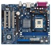
... Chassis Speaker Header (SPEAKER 1) 18 USB 2.0 Header (USB67, Blue) 19 Serial Port Connector (COM1) 20 AMR Slot (AMR1) 21 Internal Audio Connector: CD1 (Black) 22 Internal Audio Connector: AUX1 (White) 23 3 x PCI Slots (PCI1- 3) 24 Clear CMOS Jumper (CLRCMOS1) 25 JR1 / JL1 Jumpers 26 Front Panel Audio Header (AUDIO1) 27 Chassis Fan Connector (CHA_FAN1) 28 Shared USB 2.0 Header (USB4_5, Blue) 29 North Bridge Controller 30 CPU Fan Connector (CPU_FAN1) 8 1.3 Motherboard Layout PS2 Keyboard 1 23 4 20.3cm (8.0 in) PS2 Mouse 1 PS2_USB_PWR1 ATX12V1 56 1 IR1 Super I/O 4Mb BIOS PARALLEL...
... Chassis Speaker Header (SPEAKER 1) 18 USB 2.0 Header (USB67, Blue) 19 Serial Port Connector (COM1) 20 AMR Slot (AMR1) 21 Internal Audio Connector: CD1 (Black) 22 Internal Audio Connector: AUX1 (White) 23 3 x PCI Slots (PCI1- 3) 24 Clear CMOS Jumper (CLRCMOS1) 25 JR1 / JL1 Jumpers 26 Front Panel Audio Header (AUDIO1) 27 Chassis Fan Connector (CHA_FAN1) 28 Shared USB 2.0 Header (USB4_5, Blue) 29 North Bridge Controller 30 CPU Fan Connector (CPU_FAN1) 8 1.3 Motherboard Layout PS2 Keyboard 1 23 4 20.3cm (8.0 in) PS2 Mouse 1 PS2_USB_PWR1 ATX12V1 56 1 IR1 Super I/O 4Mb BIOS PARALLEL...
User Manual
Page 16
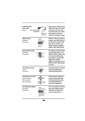
Serial ATA (SATA) Power Cable (Optional) connect to the SATA HDD power connector connect to the power supply Please connect the black end of audio devices. 16 When using the front panel USB ports by attaching the front panel USB cable to this USB 2.0 header is available to the power connector on the rear panel. R MIC-POWER MIC This is shared with the USB 2.0 ports 4,5 on ASRock I/O PlusTM will not be able to the power connector of the power supply. Internal Audio Connectors (4-pin CD1, 4-pin AUX1) (CD1: see p.8, No. 21) (AUX1...
Serial ATA (SATA) Power Cable (Optional) connect to the SATA HDD power connector connect to the power supply Please connect the black end of audio devices. 16 When using the front panel USB ports by attaching the front panel USB cable to this USB 2.0 header is available to the power connector on the rear panel. R MIC-POWER MIC This is shared with the USB 2.0 ports 4,5 on ASRock I/O PlusTM will not be able to the power connector of the power supply. Internal Audio Connectors (4-pin CD1, 4-pin AUX1) (CD1: see p.8, No. 21) (AUX1...

User Manual
Page 17
...# GND 1 DUMMY RESET# GND HDLEDHDLED+ 1 SPEAKER DUMMY DUMMY +5V This header accommodates several system front panel functions. System Panel Header (9-pin PANEL1) (see p.8, No. 16) Chassis Speaker Header (4-pin SPEAKER 1) (see p.8 item 19) RRXD1 DDTR#1 DDSR#1 CCTS#1 1 RRI#1 RRTS#1 GND TTXD1 DDCD#1 17 This COM1 connector supports a serial port module. Please connect the CPU fan cable to this connector and match the black wire to power up. Please install the heatsink and the CPU fan before installing ATX 12V connector;
...# GND 1 DUMMY RESET# GND HDLEDHDLED+ 1 SPEAKER DUMMY DUMMY +5V This header accommodates several system front panel functions. System Panel Header (9-pin PANEL1) (see p.8, No. 16) Chassis Speaker Header (4-pin SPEAKER 1) (see p.8 item 19) RRXD1 DDTR#1 DDSR#1 CCTS#1 1 RRI#1 RRTS#1 GND TTXD1 DDCD#1 17 This COM1 connector supports a serial port module. Please connect the CPU fan cable to this connector and match the black wire to power up. Please install the heatsink and the CPU fan before installing ATX 12V connector;

User Manual
Page 19
...: .. \ SATA RAID BIOS STEP 3: Install Windows 2000 / Windows XP OS on your system as the boot device. If you want to manage RAID functions, you can start to use both "SATA RAID BIOS" and "VIA RAID Tool" for RAID configuration. STEP 1: Make a SATA Driver Diskette. Please insert a floppy diskette into your optical drive to use "VIA RAID Tool" in it! Windows 98 / Windows ME does not support RAID functions. 2. Insert the ASRock Support CD into the floppy drive, and press . Start to set RAID configuration...
...: .. \ SATA RAID BIOS STEP 3: Install Windows 2000 / Windows XP OS on your system as the boot device. If you want to manage RAID functions, you can start to use both "SATA RAID BIOS" and "VIA RAID Tool" for RAID configuration. STEP 1: Make a SATA Driver Diskette. Please insert a floppy diskette into your optical drive to use "VIA RAID Tool" in it! Windows 98 / Windows ME does not support RAID functions. 2. Insert the ASRock Support CD into the floppy drive, and press . Start to set RAID configuration...

User Manual
Page 21
... the motherboard stores the BIOS SETUP UTILITY. Please press during the Power-On-Self-Test (POST) to choose among the selections on the system chassis. Because the BIOS software is constantly being updated, the following selections: Main To set up the system time/date information Advanced To set up the advanced BIOS features H/W Monitor To display current hardware status Boot To set up the default system device to locate and load the...
... the motherboard stores the BIOS SETUP UTILITY. Please press during the Power-On-Self-Test (POST) to choose among the selections on the system chassis. Because the BIOS software is constantly being updated, the following selections: Main To set up the system time/date information Advanced To set up the advanced BIOS features H/W Monitor To display current hardware status Boot To set up the default system device to locate and load the...
User Manual
Page 23
... motherboard. CPU Configuration Chipset Configuration ACPI Configuration IDE Configuration PCIPnP Configuration Floppy Configuration SuperIO Configuration USB Configuration Configure CPU Select Screen Select Item Enter Go to Sub Screen F1 General Help F9 Load Defaults F10 Save and Exit ESC Exit v02.54 (C) Copyright 1985-2003, American Megatrends, Inc. If it shows "Unlocked", you changing the ratio value of Boot Failure Guard. If it shows "Locked", then the item Ratio CMOS 23 BIOS SETUP UTILITY Main Advanced H/W Monitor Boot Security Exit Advanced Settings WARNING : Setting...
... motherboard. CPU Configuration Chipset Configuration ACPI Configuration IDE Configuration PCIPnP Configuration Floppy Configuration SuperIO Configuration USB Configuration Configure CPU Select Screen Select Item Enter Go to Sub Screen F1 General Help F9 Load Defaults F10 Save and Exit ESC Exit v02.54 (C) Copyright 1985-2003, American Megatrends, Inc. If it shows "Unlocked", you changing the ratio value of Boot Failure Guard. If it shows "Locked", then the item Ratio CMOS 23 BIOS SETUP UTILITY Main Advanced H/W Monitor Boot Security Exit Advanced Settings WARNING : Setting...
User Manual
Page 24
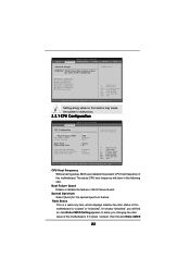
... kernel version 2.4.18 or higher. NT4.0) cannot handle the function with an Intel Pentium®4 processor that supports Hyper-Threading technology and an operating system that cannot support CPUs with extended CPUID functions. 3.3.2 Chipset Configuration BIOS SETUP UTILITY Advanced Chipset Configuration DRAM Frequency Flexibility Option DRAM CAS# Latency DRAM Command Rate DRAM Voltage AGP Voltage Primary Graphics Adapter AGP Aperture Size AGP Mode AGP Fast Write Onboard AGP Share Memory PCI Delay Transaction OnBoard LAN OnBoard AC'97 Audio Onboard MC...
... kernel version 2.4.18 or higher. NT4.0) cannot handle the function with an Intel Pentium®4 processor that supports Hyper-Threading technology and an operating system that cannot support CPUs with extended CPUID functions. 3.3.2 Chipset Configuration BIOS SETUP UTILITY Advanced Chipset Configuration DRAM Frequency Flexibility Option DRAM CAS# Latency DRAM Command Rate DRAM Voltage AGP Voltage Primary Graphics Adapter AGP Aperture Size AGP Mode AGP Fast Write Onboard AGP Share Memory PCI Delay Transaction OnBoard LAN OnBoard AC'97 Audio Onboard MC...
User Manual
Page 25
...-AGP card on this motherboard, you to enable or disable the onboard LAN feature. Disable this feature when using ISA cards that are not PCI 2.1 compliant. OnBoard AC'97 Audio Select [Auto], [Enabled], or [Disabled] for graphics memory. DRAM Voltage The default value of AGP fast write protocol support. AGP Mode The default value of this feature is set to [Auto]. When the total memory is accessing 8-bit ISA cards. PCI Delay Transaction Enable PCI Delay Transaction feature will free the PCI Bus when the CPU...
...-AGP card on this motherboard, you to enable or disable the onboard LAN feature. Disable this feature when using ISA cards that are not PCI 2.1 compliant. OnBoard AC'97 Audio Select [Auto], [Enabled], or [Disabled] for graphics memory. DRAM Voltage The default value of AGP fast write protocol support. AGP Mode The default value of this feature is set to [Auto]. When the total memory is accessing 8-bit ISA cards. PCI Delay Transaction Enable PCI Delay Transaction feature will free the PCI Bus when the CPU...
User Manual
Page 26
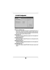
... Alarm Power On [Disabled] [Power Off] [Disabled] [Disabled] [Disabled] [Disabled] Select auto-detect or disable the STR feature. +F1 F9 F10 ESC Select Screen Select Item Change Option General Help Load Defaults Save and Exit Exit v02.54 (C) Copyright 1985-2003, American Megatrends, Inc. PCI Devices Power On Use this item to enable or disable PS/2 keyboard to turn on the system. 26 If [Power On] is selected, the AC/power remains off mode. 3.3.3 ACPI Configuration BIOS SETUP UTILITY Advanced ACPI Configuration...
... Alarm Power On [Disabled] [Power Off] [Disabled] [Disabled] [Disabled] [Disabled] Select auto-detect or disable the STR feature. +F1 F9 F10 ESC Select Screen Select Item Change Option General Help Load Defaults Save and Exit Exit v02.54 (C) Copyright 1985-2003, American Megatrends, Inc. PCI Devices Power On Use this item to enable or disable PS/2 keyboard to turn on the system. 26 If [Power On] is selected, the AC/power remains off mode. 3.3.3 ACPI Configuration BIOS SETUP UTILITY Advanced ACPI Configuration...

User Manual
Page 27
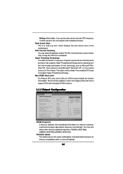
...ESC Select Screen Select Item Change Option General Help Load Defaults Save and Exit Exit v02.54 (C) Copyright 1985-2003, American Megatrends, Inc. 27 BOTH: enables both the primary and the secondary IDE channels by selecting [Both]. PRIMARY: enables only the Primary IDE Controller. SATA Operation Mode Use this option is [RAID]. OnBoard IDE Controller You may enable either the primary IDE channel or the secondary IDE channel. 3.3.4 IDE Configuration BIOS SETUP UTILITY Advanced IDE Configuration OnBoard IDE Controller SATA Operation Mode Primary IDE Master Primary IDE Slave...
...ESC Select Screen Select Item Change Option General Help Load Defaults Save and Exit Exit v02.54 (C) Copyright 1985-2003, American Megatrends, Inc. 27 BOTH: enables both the primary and the secondary IDE channels by selecting [Both]. PRIMARY: enables only the Primary IDE Controller. SATA Operation Mode Use this option is [RAID]. OnBoard IDE Controller You may enable either the primary IDE channel or the secondary IDE channel. 3.3.4 IDE Configuration BIOS SETUP UTILITY Advanced IDE Configuration OnBoard IDE Controller SATA Operation Mode Primary IDE Master Primary IDE Slave...
User Manual
Page 28
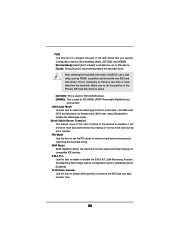
... Removable Media Device), such as FDISK, to partition and format the new IDE hard disk drives. S.M.A.R.T. TYPE Use this item to configure the type of the IDE device that you specify. LBA/Large Mode Use this item to enable or disable the S.M.A.R.T. (Self-Monitoring, Analysis, and Reporting Technology) feature. for compatible IDE devices. Configuration options: [Disabled], [Auto], [Enabled]. 32-Bit Data Transfer Use this item to enable 32-bit access to disable the use a disk utility, such as MO. After selecting the hard disk information into BIOS, use of IDE device. [Auto...
... Removable Media Device), such as FDISK, to partition and format the new IDE hard disk drives. S.M.A.R.T. TYPE Use this item to configure the type of the IDE device that you specify. LBA/Large Mode Use this item to enable or disable the S.M.A.R.T. (Self-Monitoring, Analysis, and Reporting Technology) feature. for compatible IDE devices. Configuration options: [Disabled], [Auto], [Enabled]. 32-Bit Data Transfer Use this item to enable 32-bit access to disable the use a disk utility, such as MO. After selecting the hard disk information into BIOS, use of IDE device. [Auto...
User Manual
Page 29
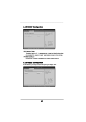
3.3.5 PCIPnP Configuration BIOS SETUP UTILITY Advanced PCI / PnP Configuration PCI Latency Timer PCI IDE BusMaster [32] [Enabled] Value in units of floppy drive connected to the system. +F1 F9 F10 ESC Select Screen Select Item Change Option General Help Load Defaults Save and Exit Exit v02.54 (C) Copyright 1985-2003, American Megatrends, Inc. 29 BIOS SETUP UTILITY Advanced Floppy Configuration Floppy A Floppy B [1.44 MB 312"] [Disabled] Select the type of PCI clocks for PCI device latency timer register. +F1 F9 F10 ESC...
3.3.5 PCIPnP Configuration BIOS SETUP UTILITY Advanced PCI / PnP Configuration PCI Latency Timer PCI IDE BusMaster [32] [Enabled] Value in units of floppy drive connected to the system. +F1 F9 F10 ESC Select Screen Select Item Change Option General Help Load Defaults Save and Exit Exit v02.54 (C) Copyright 1985-2003, American Megatrends, Inc. 29 BIOS SETUP UTILITY Advanced Floppy Configuration Floppy A Floppy B [1.44 MB 312"] [Disabled] Select the type of PCI clocks for PCI device latency timer register. +F1 F9 F10 ESC...
User Manual
Page 30
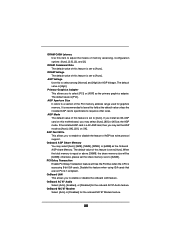
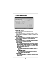
... SETUP UTILITY Advanced Configure Super IO Chipset OnBoard Floppy Controller Serial Port Address Infrared Port Address Parallel Port Address Parallel Port Mode EPP Version ECP Mode DMA Channel Parallel Port IRQ [Enabled] [3F8 / IRQ4] [Disabled] [378] [ECP + EPP] [1.9] [DMA3] [IRQ7] Allow BIOS to enable or disable floppy drive controller. Configuration options: [Disabled], [2F8 / IRQ3], and [2E8 / IRQ3]. Parallel Port Address Use this item to set the address for the parallel port. EPP Version Use this item to set the IRQ for the onboard serial port or disable it . Serial Port...
... SETUP UTILITY Advanced Configure Super IO Chipset OnBoard Floppy Controller Serial Port Address Infrared Port Address Parallel Port Address Parallel Port Mode EPP Version ECP Mode DMA Channel Parallel Port IRQ [Enabled] [3F8 / IRQ4] [Disabled] [378] [ECP + EPP] [1.9] [DMA3] [IRQ7] Allow BIOS to enable or disable floppy drive controller. Configuration options: [Disabled], [2F8 / IRQ3], and [2E8 / IRQ3]. Parallel Port Address Use this item to set the address for the parallel port. EPP Version Use this item to set the IRQ for the onboard serial port or disable it . Serial Port...

User Manual
Page 31
... BIOS SETUP UTILITY Advanced USB Configuration USB Controller USB 2.0 Support Legacy USB Support [Enabled] [Enabled] [Disabled] To enable or disable the onboard USB controllers. +F1 F9 F10 ESC Select Screen Select Item Change Option General Help Load Defaults Save and Exit Exit v02.54 (C) Copyright 1985-2003, American Megatrends, Inc. Legacy USB Support Use this item to emulate legacy I/O devices such as mouse, keyboard,... USB 2.0 Support Use this item to enable or disable the support to enable or disable the USB 2.0 support. USB Controller Use this item to auto...
... BIOS SETUP UTILITY Advanced USB Configuration USB Controller USB 2.0 Support Legacy USB Support [Enabled] [Enabled] [Disabled] To enable or disable the onboard USB controllers. +F1 F9 F10 ESC Select Screen Select Item Change Option General Help Load Defaults Save and Exit Exit v02.54 (C) Copyright 1985-2003, American Megatrends, Inc. Legacy USB Support Use this item to emulate legacy I/O devices such as mouse, keyboard,... USB 2.0 Support Use this item to enable or disable the support to enable or disable the USB 2.0 support. USB Controller Use this item to auto...

User Manual
Page 33
...Boot Settings Configuration BIOS SETUP UTILITY Boot Boot Settings Configuration Boot From Network VIA SATA Raid Utility Bootup Num-Lock [Disabled] [Enabled] [On] To enable or disable the boot from network feature. +F1 F9 F10 ESC Select Screen Select Item Change Option General Help Load Defaults Save and Exit Exit v02.54 (C) Copyright 1985-2003, American Megatrends, Inc. VIA SATA Raid Utility Use this item to enable or disable the Boot From Network feature. BIOS SETUP UTILITY Main Advanced H/W Monitor Boot Security Exit Security Settings Supervisor Password : Not Installed User...
...Boot Settings Configuration BIOS SETUP UTILITY Boot Boot Settings Configuration Boot From Network VIA SATA Raid Utility Bootup Num-Lock [Disabled] [Enabled] [On] To enable or disable the boot from network feature. +F1 F9 F10 ESC Select Screen Select Item Change Option General Help Load Defaults Save and Exit Exit v02.54 (C) Copyright 1985-2003, American Megatrends, Inc. VIA SATA Raid Utility Use this item to enable or disable the Boot From Network feature. BIOS SETUP UTILITY Main Advanced H/W Monitor Boot Security Exit Security Settings Supervisor Password : Not Installed User...

User Manual
Page 35
... activate the devices. 4.2.3 Utilities Menu The Utilities Menu shows the applications software that enhance the motherboard features. 4.2.1 Running The Support CD To begin using the support CD, insert the CD into your CD-ROM drive. 4. Please install the necessary drivers to visit ASRock's website at http://www.asrock.com; If the Main Menu did not appear automatically, locate and double click on a specific item then follow the installation wizard to install it...
... activate the devices. 4.2.3 Utilities Menu The Utilities Menu shows the applications software that enhance the motherboard features. 4.2.1 Running The Support CD To begin using the support CD, insert the CD into your CD-ROM drive. 4. Please install the necessary drivers to visit ASRock's website at http://www.asrock.com; If the Main Menu did not appear automatically, locate and double click on a specific item then follow the installation wizard to install it...


