
User Manual
Page 1
All rights reserved. 1 P4S55FX+ P4S55FX User Manual Version 1.01 Published March 2004 Copyright©2004 ASRock INC.
All rights reserved. 1 P4S55FX+ P4S55FX User Manual Version 1.01 Published March 2004 Copyright©2004 ASRock INC.
User Manual
Page 3
... Setup Menu 33 5. Power Setup Menu 32 4. Contents 1 Introduction 4 1.1 Package Contents 4 1.2 Specifications 5 1.3 Motherboard Layout (P4S55FX 7 1.4 Motherboard Layout (P4S55FX 8 1.5 ASRock I/O PlusTM (P4S55FX+/ P4S55FX 9 2 Installation 10 Pre-installation Precautions 10 2.1 CPU Installation 11 2.2 Installation of CPU Fan and Heatsink 11 2.3 Installation of Memory... 25 4.2.1 Running Support CD 25 4.2.2 Drivers Menu 25 4.2.3 Utilities Menu 25 4.2.4 ASRock "PC-DIY Live Demo" Program 25 4.2.5 Contact Information 25 Appendix 26 1. Advanced BIOS Setup Menu 26 2.
... Setup Menu 33 5. Power Setup Menu 32 4. Contents 1 Introduction 4 1.1 Package Contents 4 1.2 Specifications 5 1.3 Motherboard Layout (P4S55FX 7 1.4 Motherboard Layout (P4S55FX 8 1.5 ASRock I/O PlusTM (P4S55FX+/ P4S55FX 9 2 Installation 10 Pre-installation Precautions 10 2.1 CPU Installation 11 2.2 Installation of CPU Fan and Heatsink 11 2.3 Installation of Memory... 25 4.2.1 Running Support CD 25 4.2.2 Drivers Menu 25 4.2.3 Utilities Menu 25 4.2.4 ASRock "PC-DIY Live Demo" Program 25 4.2.5 Contact Information 25 Appendix 26 1. Advanced BIOS Setup Menu 26 2.
User Manual
Page 4
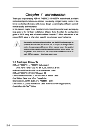
... find the latest memory and CPU support lists on page 26 for a 3.5-in , 30.5 cm x 21.8 cm) ASRock P4S55FX+ / P4S55FX Quick Installation Guide ASRock P4S55FX+ / P4S55FX Support CD One 80-conductor Ultra ATA 66/100/133 IDE Ribbon Cable One Ribbon Cable for advanced users' reference. It ... be subject to quality and endurance. In case any modifications of advanced BIOS setup is offered on ASRock website as well. ASRock website http://www.asrock.com 1.1 Package Contents ASRock P4S55FX+ or P4S55FX Motherboard (ATX Form Factor: 12.0-in x 8.6-in Floppy Drive One Serial ATA (SATA) Cable ...
... find the latest memory and CPU support lists on page 26 for a 3.5-in , 30.5 cm x 21.8 cm) ASRock P4S55FX+ / P4S55FX Quick Installation Guide ASRock P4S55FX+ / P4S55FX Support CD One 80-conductor Ultra ATA 66/100/133 IDE Ribbon Cable One Ribbon Cable for advanced users' reference. It ... be subject to quality and endurance. In case any modifications of advanced BIOS setup is offered on ASRock website as well. ASRock website http://www.asrock.com 1.1 Package Contents ASRock P4S55FX+ or P4S55FX Motherboard (ATX Form Factor: 12.0-in x 8.6-in Floppy Drive One Serial ATA (SATA) Cable ...

User Manual
Page 5
... Mode 6 Supports up to 4 IDE devices Serial ATA: 2 SATA connectors Supports up to 1.5Gb/s data transfer rate (SATA is only available on P4S55FX+ Motherboard) Floppy Port: Supports up to 2 floppy disk drives Audio: 5.1 channels AC'97 Audio LAN: Speed: 802.3u (10/100 Ethernet),... supports Wake-On-LAN Hardware Monitor: CPU temperature sensing Chassis temperature sensing CPU overheat shutdown to protect CPU life (ASRock U-COP)(see CAUTION 2) CPU fan tachometer Chassis fan tachometer Voltage monitoring: +12V, +5V, +3V, Vcore PCI slots: 5 slots with PCI ...
... Mode 6 Supports up to 4 IDE devices Serial ATA: 2 SATA connectors Supports up to 1.5Gb/s data transfer rate (SATA is only available on P4S55FX+ Motherboard) Floppy Port: Supports up to 2 floppy disk drives Audio: 5.1 channels AC'97 Audio LAN: Speed: 802.3u (10/100 Ethernet),... supports Wake-On-LAN Hardware Monitor: CPU temperature sensing Chassis temperature sensing CPU overheat shutdown to protect CPU life (ASRock U-COP)(see CAUTION 2) CPU fan tachometer Chassis fan tachometer Voltage monitoring: +12V, +5V, +3V, Vcore PCI slots: 5 slots with PCI ...

User Manual
Page 9
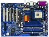
1.5 ASRock I/O PlusTM (P4S55FX+ / P4S55FX) 1 2 3 4 5 11 10 9 1 Parallel Port 2 RJ-45 Port 3 Line In (Light Blue) 4 Line Out (Lime) 5 Microphone (Pink) 6 USB 2.0 Ports (USB4, USB5) 8 7 6 7 USB 2.0 Ports (USB0, USB1) 8 USB 2.0 Ports (USB2, USB3) 9 Serial Port: COM1 10 PS/2 Keyboard Port (Purple) 11 PS/2 Mouse Port (Green) 9
1.5 ASRock I/O PlusTM (P4S55FX+ / P4S55FX) 1 2 3 4 5 11 10 9 1 Parallel Port 2 RJ-45 Port 3 Line In (Light Blue) 4 Line Out (Lime) 5 Microphone (Pink) 6 USB 2.0 Ports (USB4, USB5) 8 7 6 7 USB 2.0 Ports (USB0, USB1) 8 USB 2.0 Ports (USB2, USB3) 9 Serial Port: COM1 10 PS/2 Keyboard Port (Purple) 11 PS/2 Mouse Port (Green) 9

User Manual
Page 14
... card on P4S55FX+ / P4S55FX motherboard. Step 3. For the voltage information of your motherboard is completely seated on the slot. Remove the system unit cover (if your AGP card, please check with the slot and press firmly until the card is already installed in a chassis). Replace the system cover. 14 The ASRock AGP slot...
... card on P4S55FX+ / P4S55FX motherboard. Step 3. For the voltage information of your motherboard is completely seated on the slot. Remove the system unit cover (if your AGP card, please check with the slot and press firmly until the card is already installed in a chassis). Replace the system cover. 14 The ASRock AGP slot...
User Manual
Page 17
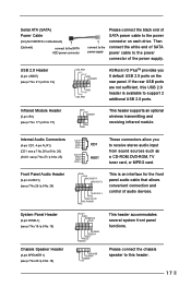
..., or MPEG card. Front Panel Audio Header (9-pin AUDIO1) (see p.7 No. 21 / p.8 No. 19) USB_PWR P-7 P+7 GND DUMMY 1 GND P+6 P-6 USB_PWR ASRock I/O PlusTM provides you to this USB 2.0 header is an interface for P4S55FX+ motherboard) (Optional) connect to the SATA HDD power connector connect to the power supply Please connect the black end of...
..., or MPEG card. Front Panel Audio Header (9-pin AUDIO1) (see p.7 No. 21 / p.8 No. 19) USB_PWR P-7 P+7 GND DUMMY 1 GND P+6 P-6 USB_PWR ASRock I/O PlusTM provides you to this USB 2.0 header is an interface for P4S55FX+ motherboard) (Optional) connect to the SATA HDD power connector connect to the power supply Please connect the black end of...

User Manual
Page 19
STEP 2: Connect one end of the second SATA data cable to the SATA hard disk. 2.8 Hot Plug and Hot Swap Functions for SATA HDDs P4S55FX+ motherboard supports Hot Plug function for HDDs. STEP 7: Connect the SATA power cable to the motherboard's secondary SATA connector (SATA2). What is Hot ...suggest you to install only one end of the SATA data cable to prevent intervention. You may install SATA hard disks on our website www.asrock.com NOTE What is Hot Swap Function? STEP 1: Install the SATA hard disks into the SATA HDD. This section will provide 2 power connectors...
STEP 2: Connect one end of the second SATA data cable to the SATA hard disk. 2.8 Hot Plug and Hot Swap Functions for SATA HDDs P4S55FX+ motherboard supports Hot Plug function for HDDs. STEP 7: Connect the SATA power cable to the motherboard's secondary SATA connector (SATA2). What is Hot ...suggest you to install only one end of the SATA data cable to prevent intervention. You may install SATA hard disks on our website www.asrock.com NOTE What is Hot Swap Function? STEP 1: Install the SATA hard disks into the SATA HDD. This section will provide 2 power connectors...


