
User Manual
Page 3
Contents 1 Introduction 4 1.1 Package Contents 4 1.2 Specifications 5 1.3 Motherboard Layout (P4AL-800 7 1.4 Motherboard Layout (P4AL-800M 8 1.5 ASRock I/OTM (P4AL-800 / P4AL-800M 9 2 Installation 10 2.1 Screw Holes 10 2.2 Pre-installation Precautions 10 2.3 CPU Installation 11 2.4 ...Support 21 4.1 Installing Operating System 21 4.2 Support CD Information 21 4.2.1 Running Support CD 21 4.2.2 Drivers Menu 21 4.2.3 Utilities Menu 21 4.2.4 ASRock "PC-DIY Live Demo" Program 21 4.2.5 Contact Information 21 Appendix: Advanced BIOS Setup 22 1 Advanced Menu 22 2 Security Menu 26 3....
Contents 1 Introduction 4 1.1 Package Contents 4 1.2 Specifications 5 1.3 Motherboard Layout (P4AL-800 7 1.4 Motherboard Layout (P4AL-800M 8 1.5 ASRock I/OTM (P4AL-800 / P4AL-800M 9 2 Installation 10 2.1 Screw Holes 10 2.2 Pre-installation Precautions 10 2.3 CPU Installation 11 2.4 ...Support 21 4.1 Installing Operating System 21 4.2 Support CD Information 21 4.2.1 Running Support CD 21 4.2.2 Drivers Menu 21 4.2.3 Utilities Menu 21 4.2.4 ASRock "PC-DIY Live Demo" Program 21 4.2.5 Contact Information 21 Appendix: Advanced BIOS Setup 22 1 Advanced Menu 22 2 Security Menu 26 3....

User Manual
Page 4
... without further notice. ASRock website http://www.asrock.com 1.1 Package Contents ASRock P4AL-800 motherboard (ATX form factor: 12.0" x 7.8", 30.5 x 19.8 cm) or ASRock P4AL-800M motherboard (Micro ATX form factor: 9.6" x 7.8", 24.4 x 19.8 cm) ASRock P4AL-800 / P4AL-800M Quick Installation Guide ASRock Intel-ALi Support CD 1 cable for IDE devices (1 x ATA 66 / 100 / 133) 1 cable for purchasing ASRock P4AL-800 / P4AL-800M motherboard, a reliable motherboard produced under ASRock's consistently stringent...
... without further notice. ASRock website http://www.asrock.com 1.1 Package Contents ASRock P4AL-800 motherboard (ATX form factor: 12.0" x 7.8", 30.5 x 19.8 cm) or ASRock P4AL-800M motherboard (Micro ATX form factor: 9.6" x 7.8", 24.4 x 19.8 cm) ASRock P4AL-800 / P4AL-800M Quick Installation Guide ASRock Intel-ALi Support CD 1 cable for IDE devices (1 x ATA 66 / 100 / 133) 1 cable for purchasing ASRock P4AL-800 / P4AL-800M motherboard, a reliable motherboard produced under ASRock's consistently stringent...

User Manual
Page 6
...; Windows® XP SP1/2000 SP4. ACPI 1.1 compliance wake up events; Supports jumperfree; Although P4AL-800 / P4AL-800M offers stepless control, it is detected, the system will also be overclocked proportionally. Please check if the CPU fan on P4AL-800 / P4AL-800M motherboard! It may cause permanent damage! 4. While CPU overheat is not recommended to spray thermal...
...; Windows® XP SP1/2000 SP4. ACPI 1.1 compliance wake up events; Supports jumperfree; Although P4AL-800 / P4AL-800M offers stepless control, it is detected, the system will also be overclocked proportionally. Please check if the CPU fan on P4AL-800 / P4AL-800M motherboard! It may cause permanent damage! 4. While CPU overheat is not recommended to spray thermal...

User Manual
Page 7
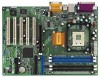
1.3 Motherboard Layout (P4AL-800) 22 36 2 19.8cm (7.8 in) PS/2 Mouse 1 PS2_USB_PWR1 PS/2 Keyboard CPU_FAN1 COM1 PGA478B 5 1 PARALLEL PORT ATXPWR1 DDR1 (64/72 bit, 184-pin module) DDR2 (64/... 25 AGP1 8 19 7 AUDIO CODEC PCI 1 Super I/O 18 2MB 11 BIOS PCI 2 ALi 16 M1563 CLRTC1 1 17 PCI 3 PCI 4 USB2.0 5.1CH CMOS Battery CHA_FAN1 PCI 5 ` P4AL-800 FLOPPY1 USB45 SPEAKER1 1 1 PANEL 1 IR1 PLED PWRBTN 1 1 HDLED RESET 9 10 13 15 14 12 1 ATX power connector (ATXPWR1) 2 CPU socket 3 CPU fan connector (CPU_FAN1) 4 North...
1.3 Motherboard Layout (P4AL-800) 22 36 2 19.8cm (7.8 in) PS/2 Mouse 1 PS2_USB_PWR1 PS/2 Keyboard CPU_FAN1 COM1 PGA478B 5 1 PARALLEL PORT ATXPWR1 DDR1 (64/72 bit, 184-pin module) DDR2 (64/... 25 AGP1 8 19 7 AUDIO CODEC PCI 1 Super I/O 18 2MB 11 BIOS PCI 2 ALi 16 M1563 CLRTC1 1 17 PCI 3 PCI 4 USB2.0 5.1CH CMOS Battery CHA_FAN1 PCI 5 ` P4AL-800 FLOPPY1 USB45 SPEAKER1 1 1 PANEL 1 IR1 PLED PWRBTN 1 1 HDLED RESET 9 10 13 15 14 12 1 ATX power connector (ATXPWR1) 2 CPU socket 3 CPU fan connector (CPU_FAN1) 4 North...

User Manual
Page 10
... in the bag that comes with the component. Before you uninstall any motherboard settings. 1. Chapter 2 Installation P4AL-800 is a Micro ATX form factor (9.6" x 7.8", 24.4 x 19.8 cm) motherboard. Failure to do so may cause physical injuries to the chassis. Whenever you install the motherboard, study the configuration of the following precautions before installing or removing the...
... in the bag that comes with the component. Before you uninstall any motherboard settings. 1. Chapter 2 Installation P4AL-800 is a Micro ATX form factor (9.6" x 7.8", 24.4 x 19.8 cm) motherboard. Failure to do so may cause physical injuries to the chassis. Whenever you install the motherboard, study the configuration of the following precautions before installing or removing the...

User Manual
Page 12
... orientation. Step 3. Align a DIMM on the slot such that the notch on the DIMM matches the break on the slot. 2.5 Installation of Memory Modules (DIMM) P4AL-800 / P4AL-800M motherboard provides three 184-pin DDR (Double Data Rate) DIMM slots.
... orientation. Step 3. Align a DIMM on the slot such that the notch on the DIMM matches the break on the slot. 2.5 Installation of Memory Modules (DIMM) P4AL-800 / P4AL-800M motherboard provides three 184-pin DDR (Double Data Rate) DIMM slots.

User Manual
Page 13
The ASRock AGP slot has a special locking mechanism which can securely fasten the graphics card ... AGP slot on the slot. Align the card connector with screws. Remove the system unit cover (if your motherboard is unplugged. Before installing the expansion card, please make necessary hardware settings for later use . Step 4. Fasten...card is used to install expansion cards that you start the installation. AGP slot: The AGP slot is completely seated on P4AL-800 / P4AL-800M motherboard! Step 5. Step 6. Please do NOT plug a 3.3V AGP card in a chassis). 2.6 Expansion Slots (PCI ...
The ASRock AGP slot has a special locking mechanism which can securely fasten the graphics card ... AGP slot on the slot. Align the card connector with screws. Remove the system unit cover (if your motherboard is unplugged. Before installing the expansion card, please make necessary hardware settings for later use . Step 4. Fasten...card is used to install expansion cards that you start the installation. AGP slot: The AGP slot is completely seated on P4AL-800 / P4AL-800M motherboard! Step 5. Step 6. Please do NOT plug a 3.3V AGP card in a chassis). 2.6 Expansion Slots (PCI ...

User Manual
Page 15
Connector FDD connector Figure Description (33-pin FLOPPY1) (see p.7/p.8 item 13) USB_PWR P-5 P+5 GND DUMMY 1 GND P+4 P-4 USB_PWR ASRock I/OTM provides you to receive stereo audio input from sound sources such as a CD-ROM, DVD/ROM, TV tuner card, or MPEG card.... audio connectors (4-pin CD1, 4-pin AUX1) (CD1: see p.7/p.8 item 24) (AUX1: see p.7/p.8 item 8) PIN1 IDE1 PIN1 IDE2 Connect this BLUE end to the motherboard 80-Pin ATA 100/133 cable Connect this USB 2.0 header is available for 2 additional USB 2.0 ports. 2.8 Connectors Connectors are not sufficient, this BLACK end to...
Connector FDD connector Figure Description (33-pin FLOPPY1) (see p.7/p.8 item 13) USB_PWR P-5 P+5 GND DUMMY 1 GND P+4 P-4 USB_PWR ASRock I/OTM provides you to receive stereo audio input from sound sources such as a CD-ROM, DVD/ROM, TV tuner card, or MPEG card.... audio connectors (4-pin CD1, 4-pin AUX1) (CD1: see p.7/p.8 item 24) (AUX1: see p.7/p.8 item 8) PIN1 IDE1 PIN1 IDE2 Connect this BLUE end to the motherboard 80-Pin ATA 100/133 cable Connect this USB 2.0 header is available for 2 additional USB 2.0 ports. 2.8 Connectors Connectors are not sufficient, this BLACK end to...

User Manual
Page 17
... exactly match what you wish to enter the BIOS Setup after POST, restart the system by pressing + + , or by pressing the reset button on the motherboard stores the BIOS Setup Utility. The BIOS Setup Utility is designed to be user-friendly.
... exactly match what you wish to enter the BIOS Setup after POST, restart the system by pressing + + , or by pressing the reset button on the motherboard stores the BIOS Setup Utility. The BIOS Setup Utility is designed to be user-friendly.

User Manual
Page 21
... find the file through the following path: ..\ MPEGAV \ AVSEQ01.DAT To see this chapter for more about ASRock, welcome to your OS documentation for general reference only. Chapter 4 Software Support 4.1 Install Operating System This motherboard supports various Microsoft® Windows® operating systems: 98 SE / ME / 2000 / XP. Install the necessary drivers...
... find the file through the following path: ..\ MPEGAV \ AVSEQ01.DAT To see this chapter for more about ASRock, welcome to your OS documentation for general reference only. Chapter 4 Software Support 4.1 Install Operating System This motherboard supports various Microsoft® Windows® operating systems: 98 SE / ME / 2000 / XP. Install the necessary drivers...

User Manual
Page 22
CPU Host Frequency: This shows current CPU host frequency of spread spectrum. DRAM Frequency: If [Auto] is selected, the motherboard will be hidden if the current CPU does not support Hyper-Threading technology. 22 This option will detect the memory module(s) inserted and ...version 2.4.18 or higher. CPU Ratio Selection: CPU Ratio is determined by the installed processor. Set to enable or disable the feature of the installed motherboard. Advanced BIOS Setup Menu Main Advanced AMIBIOS SETUP UTILITY - You can also select other value as Microsoft® Windows® XP. Whether the ...
CPU Host Frequency: This shows current CPU host frequency of spread spectrum. DRAM Frequency: If [Auto] is selected, the motherboard will be hidden if the current CPU does not support Hyper-Threading technology. 22 This option will detect the memory module(s) inserted and ...version 2.4.18 or higher. CPU Ratio Selection: CPU Ratio is determined by the installed processor. Set to enable or disable the feature of the installed motherboard. Advanced BIOS Setup Menu Main Advanced AMIBIOS SETUP UTILITY - You can also select other value as Microsoft® Windows® XP. Whether the ...

User Manual
Page 25
.... OnBoard AC'97 Audio: Select [Disabled], [Auto] or [Enabled] for Midi Port or disable Midi Port. The default value is set addresses for CPU temperature, Motherboard temperature, CPU fan speed, and critical voltage. Or you to [Disabled] will show the EPP version in the following item, "EPP Version". Advanced AMIBIOS SETUP...
.... OnBoard AC'97 Audio: Select [Disabled], [Auto] or [Enabled] for Midi Port or disable Midi Port. The default value is set addresses for CPU temperature, Motherboard temperature, CPU fan speed, and critical voltage. Or you to [Disabled] will show the EPP version in the following item, "EPP Version". Advanced AMIBIOS SETUP...

