
User Manual
Page 5
... 5 1.2 Specifications Platform: P4AL-800: ATX form factor (12.0" x 7.8", 30.5 x 19.8 cm) P4AL-800M: CPU: Micro ATX form factor (9.6" x 7.8", 24.4 x 19.8 cm) Socket 478 for Intel® Pentium® 4 / Celeron® processor Chipsets: North Bridge: A800N chipset, FSB @ 800/533/400 MHz, supports ...DDR333) for three DDR DIMM slots, Max. 3.5GB; Can connect up to protect CPU life (ASRock U-COP)(see CAUTION 2); Chassis fan tachometer PCI slots: P4AL-800: 5 slots with PCI Specification 2.2 P4AL-800M: 2 slots with PCI Specification 2.2 AGP slot: 1 AGP slot, supports 1.5V, 8X...
... 5 1.2 Specifications Platform: P4AL-800: ATX form factor (12.0" x 7.8", 30.5 x 19.8 cm) P4AL-800M: CPU: Micro ATX form factor (9.6" x 7.8", 24.4 x 19.8 cm) Socket 478 for Intel® Pentium® 4 / Celeron® processor Chipsets: North Bridge: A800N chipset, FSB @ 800/533/400 MHz, supports ...DDR333) for three DDR DIMM slots, Max. 3.5GB; Can connect up to protect CPU life (ASRock U-COP)(see CAUTION 2); Chassis fan tachometer PCI slots: P4AL-800: 5 slots with PCI Specification 2.2 P4AL-800M: 2 slots with PCI Specification 2.2 AGP slot: 1 AGP slot, supports 1.5V, 8X...

User Manual
Page 7
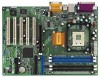
1.3 Motherboard Layout (P4AL-800) 22 36 2 19.8cm (7.8 in) PS/2 Mouse 1 PS2_USB_PWR1 PS/2 Keyboard CPU_FAN1 COM1 PGA478B 5 1 PARALLEL PORT ATXPWR1 DDR1 (64/72 bit, 184-pin module) DDR2 (64/... BIOS PCI 2 ALi 16 M1563 CLRTC1 1 17 PCI 3 PCI 4 USB2.0 5.1CH CMOS Battery CHA_FAN1 PCI 5 ` P4AL-800 FLOPPY1 USB45 SPEAKER1 1 1 PANEL 1 IR1 PLED PWRBTN 1 1 HDLED RESET 9 10 13 15 14 12 1 ATX power connector (ATXPWR1) 2 CPU socket 3 CPU fan connector (CPU_FAN1) 4 North Bridge controller 5 184-pin DDR DIMM slots 6 CPU heatsink retention module...
1.3 Motherboard Layout (P4AL-800) 22 36 2 19.8cm (7.8 in) PS/2 Mouse 1 PS2_USB_PWR1 PS/2 Keyboard CPU_FAN1 COM1 PGA478B 5 1 PARALLEL PORT ATXPWR1 DDR1 (64/72 bit, 184-pin module) DDR2 (64/... BIOS PCI 2 ALi 16 M1563 CLRTC1 1 17 PCI 3 PCI 4 USB2.0 5.1CH CMOS Battery CHA_FAN1 PCI 5 ` P4AL-800 FLOPPY1 USB45 SPEAKER1 1 1 PANEL 1 IR1 PLED PWRBTN 1 1 HDLED RESET 9 10 13 15 14 12 1 ATX power connector (ATXPWR1) 2 CPU socket 3 CPU fan connector (CPU_FAN1) 4 North Bridge controller 5 184-pin DDR DIMM slots 6 CPU heatsink retention module...

User Manual
Page 10
Chapter 2 Installation P4AL-800 is a Micro ATX form factor (9.6" x 7.8", 24.4 x 19.8 cm) motherboard. Failure to do so may...Make sure to unplug the power cord before you and damages to the chassis. Unplug the power cord from the power supply. P4AL-800M is an ATX form factor (12.0" x 7.8", 30.5 x 19.8 cm) motherboard; Before you install the motherboard, ... physical injuries to ensure that the power is switched off or the power cord is detached from the wall socket before you install or remove any component. 2. To avoid damaging the motherboard components due to static electricity, ...
Chapter 2 Installation P4AL-800 is a Micro ATX form factor (9.6" x 7.8", 24.4 x 19.8 cm) motherboard. Failure to do so may...Make sure to unplug the power cord before you and damages to the chassis. Unplug the power cord from the power supply. P4AL-800M is an ATX form factor (12.0" x 7.8", 30.5 x 19.8 cm) motherboard; Before you install the motherboard, ... physical injuries to ensure that the power is switched off or the power cord is detached from the wall socket before you install or remove any component. 2. To avoid damaging the motherboard components due to static electricity, ...

User Manual
Page 11
... connector (CPU_FAN1, see pages 7 and 8, No. 3). Step 1 Step 2, 3 Step 4 2.4 Installation of the socket lever. DO NOT force the CPU into the socket until it firmly on the socket while you push down the socket lever to the instruction manuals of the pins. For proper installation, please kindly refer to secure... is also needed to avoid bending of the CPU fan and heatsink vendors. 11 Step 3. Carefully insert the CPU into the socket to improve heat dissipation. Make sure that it is in place, press it fits in one correct orientation. 2.3 CPU Installation Step 1. Step 2....
... connector (CPU_FAN1, see pages 7 and 8, No. 3). Step 1 Step 2, 3 Step 4 2.4 Installation of the socket lever. DO NOT force the CPU into the socket until it firmly on the socket while you push down the socket lever to the instruction manuals of the pins. For proper installation, please kindly refer to secure... is also needed to avoid bending of the CPU fan and heatsink vendors. 11 Step 3. Carefully insert the CPU into the socket to improve heat dissipation. Make sure that it is in place, press it fits in one correct orientation. 2.3 CPU Installation Step 1. Step 2....