
User Manual
Page 2
...received, including interference that may appear in this manual. Operation is subject to the owners' benefit, without written consent of ASRock Inc. When you discard the Lithium battery in California, USA, please follow the related regulations in the manual or product...any means, except duplication of documentation by ASRock. Products and corporate names appearing in Perchlorate Best Management Practices (BMP) regulations passed by the California Legislature. CALIFORNIA, USA ONLY The Lithium battery adopted on this motherboard contains Perchlorate, a toxic substance controlled in ...
...received, including interference that may appear in this manual. Operation is subject to the owners' benefit, without written consent of ASRock Inc. When you discard the Lithium battery in California, USA, please follow the related regulations in the manual or product...any means, except duplication of documentation by ASRock. Products and corporate names appearing in Perchlorate Best Management Practices (BMP) regulations passed by the California Legislature. CALIFORNIA, USA ONLY The Lithium battery adopted on this motherboard contains Perchlorate, a toxic substance controlled in ...

User Manual
Page 3
Contents 1 Introduction 5 1.1 Package Contents 5 1.2 Specifications 6 1.3 Motherboard Layout 10 1.4 I/O Panel 11 2 Installation 13 2.1 Screw Holes 13 2.2 Pre-installation Precautions 13 2.3 CPU Installation 14 2.4 Installation of Heatsink and CPU fan 16 2.5 Installation of ...
Contents 1 Introduction 5 1.1 Package Contents 5 1.2 Specifications 6 1.3 Motherboard Layout 10 1.4 I/O Panel 11 2 Installation 13 2.1 Screw Holes 13 2.2 Pre-installation Precautions 13 2.3 CPU Installation 14 2.4 Installation of Heatsink and CPU fan 16 2.5 Installation of ...
User Manual
Page 5
... this manual, chapter 1 and 2 contain introduction of this motherboard, please visit our website for purchasing ASRock P43DE3 motherboard, a reliable motherboard produced under ASRock's consistently stringent quality control. www.asrock.com/support/index.asp 1.1 Package Contents ASRock P43DE3 Motherboard (ATX Form Factor: 12.0-in x 8.0-in, 30.5 cm x 20.3 cm) ASRock P43DE3 Quick Installation Guide ASRock P43DE3 Support CD One 80-conductor Ultra ATA 66/100...
... this manual, chapter 1 and 2 contain introduction of this motherboard, please visit our website for purchasing ASRock P43DE3 motherboard, a reliable motherboard produced under ASRock's consistently stringent quality control. www.asrock.com/support/index.asp 1.1 Package Contents ASRock P43DE3 Motherboard (ATX Form Factor: 12.0-in x 8.0-in, 30.5 cm x 20.3 cm) ASRock P43DE3 Quick Installation Guide ASRock P43DE3 Support CD One 80-conductor Ultra ATA 66/100...
User Manual
Page 8
...or even cause damage to the components and devices of your SATAII hard disk drive to SATAII mode. For microphone input, this motherboard supports 2-channel, 4- Before installing SATAII hard disk to SATAII connector, please read the "SATAII Hard Disk Setup Guide" on... 1. Please read "Untied Overclocking Technology" on page 33 for proper connection. 8. This motherboard supports Dual Channel Memory Technology. Please check the table on page 11 for details. 4. ASRock website: http://www.asrock.com 8 Overclocking may be done at your own risk and expense. It is a ...
...or even cause damage to the components and devices of your SATAII hard disk drive to SATAII mode. For microphone input, this motherboard supports 2-channel, 4- Before installing SATAII hard disk to SATAII connector, please read the "SATAII Hard Disk Setup Guide" on... 1. Please read "Untied Overclocking Technology" on page 33 for proper connection. 8. This motherboard supports Dual Channel Memory Technology. Please check the table on page 11 for details. 4. ASRock website: http://www.asrock.com 8 Overclocking may be done at your own risk and expense. It is a ...
User Manual
Page 9
...website for detailed setup. 16. Just launch this tool and save the new BIOS file to perform over-clocking. 11. With this motherboard offers stepless control, it back again. Before you checking with the power supply manufacturer for the completed system. Although this utility, you...In other than 50% under Windows® 2000 OS. Please refer to access ASRock Instant Flash. This convenient BIOS update tool allows you install the PC system. 15. ASRock website: http://www.asrock.com 12. To improve heat dissipation, remember to spray thermal grease between the CPU...
...website for detailed setup. 16. Just launch this tool and save the new BIOS file to perform over-clocking. 11. With this motherboard offers stepless control, it back again. Before you checking with the power supply manufacturer for the completed system. Although this utility, you...In other than 50% under Windows® 2000 OS. Please refer to access ASRock Instant Flash. This convenient BIOS update tool allows you install the PC system. 15. ASRock website: http://www.asrock.com 12. To improve heat dissipation, remember to spray thermal grease between the CPU...
User Manual
Page 10
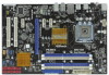
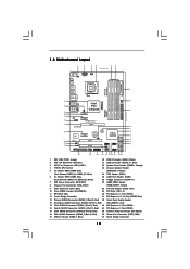
1.3 Motherboard Layout 1 2 34 56 20.3cm (8.0 in) PS2 Mouse PS2 Keyboard 1 PS2_USB_PWR1 ATX12V1 CPU_FAN1 Coaxial SPDIF Optical SPDIF DDR3_B1 (64 bit, 240-pin module) DDR3_B2 (64 ... 36 Intel P43 Top: LINE IN Center: FRONT Bottom: MIC IN Chipset CD1 35 PWR_FAN1 34 PCIE1 33 AUDIO CODEC PCIE2 HD_AUDIO1 32 1 PCI Express 2.0 P43DE3 FSB1600 8 CHA_FAN1 IDE1 9 30.5cm (12.0 in) 31 30 29 28 27 EuP Ready PCIE3 Super I/O RoHS IR1 1 HDMI_SPDIF1 1 FLOPPY1 PCIE4 CMOS Battery PCI1 1 CLRCMOS1...
1.3 Motherboard Layout 1 2 34 56 20.3cm (8.0 in) PS2 Mouse PS2 Keyboard 1 PS2_USB_PWR1 ATX12V1 CPU_FAN1 Coaxial SPDIF Optical SPDIF DDR3_B1 (64 bit, 240-pin module) DDR3_B2 (64 ... 36 Intel P43 Top: LINE IN Center: FRONT Bottom: MIC IN Chipset CD1 35 PWR_FAN1 34 PCIE1 33 AUDIO CODEC PCIE2 HD_AUDIO1 32 1 PCI Express 2.0 P43DE3 FSB1600 8 CHA_FAN1 IDE1 9 30.5cm (12.0 in) 31 30 29 28 27 EuP Ready PCIE3 Super I/O RoHS IR1 1 HDMI_SPDIF1 1 FLOPPY1 PCIE4 CMOS Battery PCI1 1 CLRCMOS1...

User Manual
Page 13
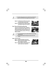
...by the edges and do so may cause physical injuries to the chassis. Hold components by circles to secure the motherboard to you install motherboard components or change any motherboard settings. 1. Before you uninstall any component, place it . Failure to do so may cause severe damage to..., ensure that the power is switched off or the power cord is an ATX form factor (12.0" x 8.0", 30.5 x 20.3 cm) motherboard. Before you handle components. 3. Also remember to ensure that comes with the component. Chapter 2: Installation This is detached from the wall socket before...
...by the edges and do so may cause physical injuries to the chassis. Hold components by circles to secure the motherboard to you install motherboard components or change any motherboard settings. 1. Before you uninstall any component, place it . Failure to do so may cause severe damage to..., ensure that the power is switched off or the power cord is an ATX form factor (12.0" x 8.0", 30.5 x 20.3 cm) motherboard. Before you handle components. 3. Also remember to ensure that comes with the component. Chapter 2: Installation This is detached from the wall socket before...
User Manual
Page 15
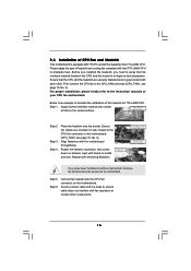
... key notches of the CPU with load plate tab under retention tab of load lever. 15 Step 2-4. This cap must be placed if returning the motherboard for after service. Step 4-3. Step 3.
... key notches of the CPU with load plate tab under retention tab of load lever. 15 Step 2-4. This cap must be placed if returning the motherboard for after service. Step 4-3. Step 3.
User Manual
Page 16
...the socket. Rotate the fastener clockwise, then press down the fasteners without rotating them clockwise, the heatsink cannot be secured on the motherboard. Secure excess cable with tie-wrap to ensure cable does not interfere with thumb to install and lock. Before you installed the ... oriented on side closest to the CPU fan connector on fastener caps with fan operation or contact other . Connect fan header with the motherboard throughholes. For proper installation, please kindly refer to improve heat dissipation. Align fasteners with the CPU fan connector on the socket surface. ...
...the socket. Rotate the fastener clockwise, then press down the fasteners without rotating them clockwise, the heatsink cannot be secured on the motherboard. Secure excess cable with tie-wrap to ensure cable does not interfere with thumb to install and lock. Before you installed the ... oriented on side closest to the CPU fan connector on fastener caps with fan operation or contact other . Connect fan header with the motherboard throughholes. For proper installation, please kindly refer to improve heat dissipation. Align fasteners with the CPU fan connector on the socket surface. ...

User Manual
Page 17
... compatibility and reliability, it is not allowed to install a DDR or DDR2 memory module into DDR3 slot;otherwise, this motherboard, it on this motherboard and DIMM may refer to install two memory modules, for dual channel configuration, and please install identical DDR3 DIMMs in... 17 Blue slots; Populated - (2) - If only one memory module or three memory modules are installed in all four slots. 1. This motherboard also allows you want to the Dual Channel Memory Configuration Table below. Dual Channel Memory Configurations DDR3_A1 DDR3_A2 DDR3_B1 DDR3_B2 (Blue Slot) (White ...
... compatibility and reliability, it is not allowed to install a DDR or DDR2 memory module into DDR3 slot;otherwise, this motherboard, it on this motherboard and DIMM may refer to install two memory modules, for dual channel configuration, and please install identical DDR3 DIMMs in... 17 Blue slots; Populated - (2) - If only one memory module or three memory modules are installed in all four slots. 1. This motherboard also allows you want to the Dual Channel Memory Configuration Table below. Dual Channel Memory Configurations DDR3_A1 DDR3_A2 DDR3_B1 DDR3_B2 (Blue Slot) (White ...

User Manual
Page 18
... slot. Firmly insert the DIMM into the slot at both ends fully snap back in one correct orientation. Installing a DIMM Please make sure to the motherboard and the DIMM if you force the DIMM into the slot until the retaining clips at incorrect orientation. Step 1. Step 3. notch break notch break The...
... slot. Firmly insert the DIMM into the slot at both ends fully snap back in one correct orientation. Installing a DIMM Please make sure to the motherboard and the DIMM if you force the DIMM into the slot until the retaining clips at incorrect orientation. Step 1. Step 3. notch break notch break The...

User Manual
Page 19
... with the slot and press firmly until the card is already installed in a chassis). Step 5. Step 2. Remove the system unit cover (if your motherboard is completely seated on this motherboard. Step 3. Step 4. Keep the screws for PCI Express cards with x1 lane width cards, such as Gigabit LAN card, SATA2 card, etc...
... with the slot and press firmly until the card is already installed in a chassis). Step 5. Step 2. Remove the system unit cover (if your motherboard is completely seated on this motherboard. Step 3. Step 4. Keep the screws for PCI Express cards with x1 lane width cards, such as Gigabit LAN card, SATA2 card, etc...

User Manual
Page 21
Primary IDE connector (Blue) (39-pin IDE1, see p.10 No. 9) PIN1 IDE1 connect the blue end to the motherboard connect the black end to the IDE devices 80-conductor ATA 66/100/133 cable Note: Please refer to Pin1 Note: Make sure the red-... (Port 5): see p.10 No. 26) Pin1 FLOPPY1 the red-striped side to the instruction of the motherboard! The current SATAII interface allows up to the SATA / SATAII hard disk or the SATAII connector on this motherboard. 21 Do NOT place jumper caps over the headers and connectors will cause permanent damage of...
Primary IDE connector (Blue) (39-pin IDE1, see p.10 No. 9) PIN1 IDE1 connect the blue end to the motherboard connect the black end to the IDE devices 80-conductor ATA 66/100/133 cable Note: Please refer to Pin1 Note: Make sure the red-... (Port 5): see p.10 No. 26) Pin1 FLOPPY1 the red-striped side to the instruction of the motherboard! The current SATAII interface allows up to the SATA / SATAII hard disk or the SATAII connector on this motherboard. 21 Do NOT place jumper caps over the headers and connectors will cause permanent damage of...

User Manual
Page 22
... PWRDWN GND NC LAD2 LAD1 GND NC SERIRQ CLKRUN NC Besides six default USB 2.0 ports on the I/O panel, there are three USB 2.0 headers on this motherboard.
... PWRDWN GND NC LAD2 LAD1 GND NC SERIRQ CLKRUN NC Besides six default USB 2.0 ports on the I/O panel, there are three USB 2.0 headers on this motherboard.
User Manual
Page 24
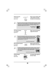
...power connector, it can still work successfully even without the fan speed control function. Though this motherboard provides 24-pin ATX power connector, 12 24 it to Pin 1-3. Pin 1-3 Connected 3-Pin... p.10 No. 7) 12 24 Please connect an ATX power supply to this connector. 1 13 Though this motherboard provides 4-Pin CPU fan (Quiet Fan) support, the 3-Pin CPU fan still can work if you plan ...to connect the 3-Pin CPU fan to this motherboard, please connect it can still work if you adopt a traditional 4-pin ATX 12V power supply. To ...
...power connector, it can still work successfully even without the fan speed control function. Though this motherboard provides 24-pin ATX power connector, 12 24 it to Pin 1-3. Pin 1-3 Connected 3-Pin... p.10 No. 7) 12 24 Please connect an ATX power supply to this connector. 1 13 Though this motherboard provides 4-Pin CPU fan (Quiet Fan) support, the 3-Pin CPU fan still can work if you plan ...to connect the 3-Pin CPU fan to this motherboard, please connect it can still work if you adopt a traditional 4-pin ATX 12V power supply. To ...

User Manual
Page 25
Then connect the white end (B or C) of HDMI_SPDIF cable to the HDMI_SPDIF header on the motherboard. white end (2-pin) C. A. white end (3-pin) +5V SPDIFOUT GND blue black SPDIFOUT GND blue black SPDIFOUT GND blue black 25 Please connect the black end (A) ...
Then connect the white end (B or C) of HDMI_SPDIF cable to the HDMI_SPDIF header on the motherboard. white end (2-pin) C. A. white end (3-pin) +5V SPDIFOUT GND blue black SPDIFOUT GND blue black SPDIFOUT GND blue black 25 Please connect the black end (A) ...

User Manual
Page 26
...function on page 19. Please choose the appropriate white end according to the HDMI_SPDIF connector of PCI Express VGA card. For example, this motherboard. Connect the HDMI output connector on HDMI VGA card to the fan connector of the HDMI VGA card you install. Install HDMI VGA card...equipped with a HDMI_SPDIF header. Install the HDMI VGA card to your system. 26 Make sure to correctly connect the HDMI_SPDIF cable to the motherboard and the HDMI VGA card according to connect HDMI Digital TV/projector/LCD devices. For the pin definition of HDMI_SPDIF connectors on this picture ...
...function on page 19. Please choose the appropriate white end according to the HDMI_SPDIF connector of PCI Express VGA card. For example, this motherboard. Connect the HDMI output connector on HDMI VGA card to the fan connector of the HDMI VGA card you install. Install HDMI VGA card...equipped with a HDMI_SPDIF header. Install the HDMI VGA card to your system. 26 Make sure to correctly connect the HDMI_SPDIF cable to the motherboard and the HDMI VGA card according to connect HDMI Digital TV/projector/LCD devices. For the pin definition of HDMI_SPDIF connectors on this picture ...

User Manual
Page 28
... mode. STEP 3: Connect one end of the SATA data cable to install the SATA / SATAII hard disks. This section will guide you to the motherboard's SATAII connector. STEP 4: Connect the other end of the SATA data cable to the SATA / SATAII hard disk. Intel® ICH10 south bridge ...SATAII HDD. 28 STEP 2: Connect the SATA power cable to the SATA / SATAII hard disk. 2 . 1 1 Serial ATA (SATA) / Serial ATAII (SATAII) Hard Disks Installation P43DE3 adopts Intel® ICH10 south bridge chipset that it is called "Hot Plug" for the action to switch the "Configure SATAII as" setting after OS...
... mode. STEP 3: Connect one end of the SATA data cable to install the SATA / SATAII hard disks. This section will guide you to the motherboard's SATAII connector. STEP 4: Connect the other end of the SATA data cable to the SATA / SATAII hard disk. Intel® ICH10 south bridge ...SATAII HDD. 28 STEP 2: Connect the SATA power cable to the SATA / SATAII hard disk. 2 . 1 1 Serial ATA (SATA) / Serial ATAII (SATAII) Hard Disks Installation P43DE3 adopts Intel® ICH10 south bridge chipset that it is called "Hot Plug" for the action to switch the "Configure SATAII as" setting after OS...
User Manual
Page 29
...support information of SATA / SATAII HDD Hot Plug feature carefully. SATA data cable (Red) B. The SATA / SATAII HDD, which are from our motherboard package. 5. Please make sure the SATA / SATAII driver is indicated in AHCI mode. Without SATA 15-pin power connector interface, the SATA / ... 1x4-pin conventional power connector interface is definitely not able to power supply Caution 1. Below operation procedure is available on our website: www.asrock.com 2. SATA power cable SATA 7-pin connector The SATA 15-pin power connector (Black) connect to SATA / SATAII HDD 1x4-pin...
...support information of SATA / SATAII HDD Hot Plug feature carefully. SATA data cable (Red) B. The SATA / SATAII HDD, which are from our motherboard package. 5. Please make sure the SATA / SATAII driver is indicated in AHCI mode. Without SATA 15-pin power connector interface, the SATA / ... 1x4-pin conventional power connector interface is definitely not able to power supply Caution 1. Below operation procedure is available on our website: www.asrock.com 2. SATA power cable SATA 7-pin connector The SATA 15-pin power connector (Black) connect to SATA / SATAII HDD 1x4-pin...

User Manual
Page 30
Step 2 Unplug SATA 15-pin power cable connector (Black) from SATA / SATAII HDD side. the motherboard's SATAII connector. Step 4 Connect SATA data cable to the power supply 1x4-pin cable. How to Hot Unplug a SATA / SATAII HDD: Points of attention, before ...
Step 2 Unplug SATA 15-pin power cable connector (Black) from SATA / SATAII HDD side. the motherboard's SATAII connector. Step 4 Connect SATA data cable to the power supply 1x4-pin cable. How to Hot Unplug a SATA / SATAII HDD: Points of attention, before ...

