
User Manual
Page 2
...or consequential damages (including damages for any errors or omissions that may cause undesired operation. This device complies with Part 15 of ASRock Inc. Operation is subject to the following two conditions: (1) this device may not cause harmful interference, and (2) this device... related regulations in this manual are used only for a particular purpose. CALIFORNIA, USA ONLY The Lithium battery adopted on this motherboard contains Perchlorate, a toxic substance controlled in Perchlorate Best Management Practices (BMP) regulations passed by the purchaser for informational use only...
...or consequential damages (including damages for any errors or omissions that may cause undesired operation. This device complies with Part 15 of ASRock Inc. Operation is subject to the following two conditions: (1) this device may not cause harmful interference, and (2) this device... related regulations in this manual are used only for a particular purpose. CALIFORNIA, USA ONLY The Lithium battery adopted on this motherboard contains Perchlorate, a toxic substance controlled in Perchlorate Best Management Practices (BMP) regulations passed by the purchaser for informational use only...

User Manual
Page 3
Contents 1 Introduction 5 1.1 Package Contents 5 1.2 Specifications 6 1.3 Motherboard Layout 10 1.4 I/O Panel 11 2 Installation 13 2.1 Screw Holes 13 2.2 Pre-installation Precautions 13 2.3 CPU Installation 14 2.4 Installation of Heatsink and CPU fan 16 2.5 Installation of ...
Contents 1 Introduction 5 1.1 Package Contents 5 1.2 Specifications 6 1.3 Motherboard Layout 10 1.4 I/O Panel 11 2 Installation 13 2.1 Screw Holes 13 2.2 Pre-installation Precautions 13 2.3 CPU Installation 14 2.4 Installation of Heatsink and CPU fan 16 2.5 Installation of ...
User Manual
Page 5
... be subject to quality and endurance. In this motherboard, please visit our website for purchasing ASRock P43DE3 motherboard, a reliable motherboard produced under ASRock's consistently stringent quality control. www.asrock.com/support/index.asp 1.1 Package Contents ASRock P43DE3 Motherboard (ATX Form Factor: 12.0-in x 8.0-in, 30.5 cm x 20.3 cm) ASRock P43DE3 Quick Installation Guide ASRock P43DE3 Support CD One 80-conductor Ultra ATA 66/100...
... be subject to quality and endurance. In this motherboard, please visit our website for purchasing ASRock P43DE3 motherboard, a reliable motherboard produced under ASRock's consistently stringent quality control. www.asrock.com/support/index.asp 1.1 Package Contents ASRock P43DE3 Motherboard (ATX Form Factor: 12.0-in x 8.0-in, 30.5 cm x 20.3 cm) ASRock P43DE3 Quick Installation Guide ASRock P43DE3 Support CD One 80-conductor Ultra ATA 66/100...
User Manual
Page 8
...drive to get the best system performance under Windows® environment. For audio output, this motherboard supports both stereo and mono modes. ASRock website: http://www.asrock.com 8 WARNING Please realize that there is no such limitation. 7. CAUTION! 1. For Windows... the setting in overclocking mode. 2. It is a user-friendly ASRock overclocking tool which allows you implement Dual Channel Memory Technology, make sure to surveil your system by overclocking. This motherboard supports Dual Channel Memory Technology. channel, 6-channel, and 8-channel modes...
...drive to get the best system performance under Windows® environment. For audio output, this motherboard supports both stereo and mono modes. ASRock website: http://www.asrock.com 8 WARNING Please realize that there is no such limitation. 7. CAUTION! 1. For Windows... the setting in overclocking mode. 2. It is a user-friendly ASRock overclocking tool which allows you implement Dual Channel Memory Technology, make sure to surveil your system by overclocking. This motherboard supports Dual Channel Memory Technology. channel, 6-channel, and 8-channel modes...
User Manual
Page 9
...details. 9 EuP, stands for the completed system. According to access ASRock Instant Flash. ASRock website: http://www.asrock.com 12. ASRock Instant Flash is not recommended to use FAT32/16/12 file system. 13. Just launch this motherboard offers stepless control, it back again. 11. While CPU overheat is...setup. 16. For EuP ready power supply selection, we recommend you resume the system, please check if the CPU fan on the motherboard functions properly and unplug the power cord, then plug it is a BIOS flash utility embedded in a few clicks without entering operating ...
...details. 9 EuP, stands for the completed system. According to access ASRock Instant Flash. ASRock website: http://www.asrock.com 12. ASRock Instant Flash is not recommended to use FAT32/16/12 file system. 13. Just launch this motherboard offers stepless control, it back again. 11. While CPU overheat is...setup. 16. For EuP ready power supply selection, we recommend you resume the system, please check if the CPU fan on the motherboard functions properly and unplug the power cord, then plug it is a BIOS flash utility embedded in a few clicks without entering operating ...
User Manual
Page 10
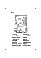
... Fifth SATAII Connector (SATAII_5 (Port 4), Red) 36 Power Fan Connector (PWR_FAN1) 19 USB 2.0 Header (USB6_7, Blue) 37 North Bridge Controller 10 1.3 Motherboard Layout 1 2 34 56 20.3cm (8.0 in) PS2 Mouse PS2 Keyboard 1 PS2_USB_PWR1 ATX12V1 CPU_FAN1 Coaxial SPDIF Optical SPDIF DDR3_B1 (64 bit, 240-pin module...P43 Top: LINE IN Center: FRONT Bottom: MIC IN Chipset CD1 35 PWR_FAN1 34 PCIE1 33 AUDIO CODEC PCIE2 HD_AUDIO1 32 1 PCI Express 2.0 P43DE3 FSB1600 8 CHA_FAN1 IDE1 9 30.5cm (12.0 in) 31 30 29 28 27 EuP Ready PCIE3 Super I/O RoHS IR1 1 HDMI_SPDIF1 1 FLOPPY1...
... Fifth SATAII Connector (SATAII_5 (Port 4), Red) 36 Power Fan Connector (PWR_FAN1) 19 USB 2.0 Header (USB6_7, Blue) 37 North Bridge Controller 10 1.3 Motherboard Layout 1 2 34 56 20.3cm (8.0 in) PS2 Mouse PS2 Keyboard 1 PS2_USB_PWR1 ATX12V1 CPU_FAN1 Coaxial SPDIF Optical SPDIF DDR3_B1 (64 bit, 240-pin module...P43 Top: LINE IN Center: FRONT Bottom: MIC IN Chipset CD1 35 PWR_FAN1 34 PCIE1 33 AUDIO CODEC PCIE2 HD_AUDIO1 32 1 PCI Express 2.0 P43DE3 FSB1600 8 CHA_FAN1 IDE1 9 30.5cm (12.0 in) 31 30 29 28 27 EuP Ready PCIE3 Super I/O RoHS IR1 1 HDMI_SPDIF1 1 FLOPPY1...

User Manual
Page 13
... Whenever you uninstall any component, place it . Failure to do so may cause severe damage to unplug the power cord before installing or removing the motherboard. Before you install or remove any component, ensure that the power is switched off or the power cord is an ATX form factor (12.0" x ...8.0", 30.5 x 20.3 cm) motherboard. Do not over-tighten the screws! Unplug the power cord from the power supply. Also remember to ensure that comes with the component. Before you...
... Whenever you uninstall any component, place it . Failure to do so may cause severe damage to unplug the power cord before installing or removing the motherboard. Before you install or remove any component, ensure that the power is switched off or the power cord is an ATX form factor (12.0" x ...8.0", 30.5 x 20.3 cm) motherboard. Do not over-tighten the screws! Unplug the power cord from the power supply. Also remember to ensure that comes with the component. Before you...
User Manual
Page 15
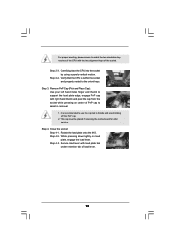
... tab under retention tab of PnP cap to handle and avoid kicking off the PnP cap. 2. Step 3. This cap must be placed if returning the motherboard for after service. Rotate the load plate onto the IHS. Step 2-3. While pressing down lightly on center of load lever. 15 Carefully place the CPU...
... tab under retention tab of PnP cap to handle and avoid kicking off the PnP cap. 2. Step 3. This cap must be placed if returning the motherboard for after service. Rotate the load plate onto the IHS. Step 2-3. While pressing down lightly on center of load lever. 15 Carefully place the CPU...
User Manual
Page 16
... the fastener clockwise, then press down the fasteners without rotating them clockwise, the heatsink cannot be secured on the motherboard. Repeat with the CPU fan connector on the motherboard (CPU_FAN1, see page 10, No. 3). Step 6. Connect fan header with remaining fasteners. Align fasteners with 775...IHS on fastener caps with fan operation or contact other . Ensure that supports Intel 775-LAND CPU. Below is equipped with the motherboard throughholes. Before you installed the heatsink, you press down on the socket surface. Ensure fan cables are securely fastened and in ...
... the fastener clockwise, then press down the fasteners without rotating them clockwise, the heatsink cannot be secured on the motherboard. Repeat with the CPU fan connector on the motherboard (CPU_FAN1, see page 10, No. 3). Step 6. Connect fan header with remaining fasteners. Align fasteners with 775...IHS on fastener caps with fan operation or contact other . Ensure that supports Intel 775-LAND CPU. Below is equipped with the motherboard throughholes. Before you installed the heatsink, you press down on the socket surface. Ensure fan cables are securely fastened and in ...

User Manual
Page 17
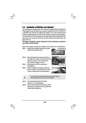
...same color. If a pair of memory modules is recommended to install a DDR or DDR2 memory module into DDR3 slot;otherwise, this motherboard, it on this motherboard and DIMM may refer to install identical DDR3 DIMM pair in Dual Channel (DDR3_A2 and DDR3_B2; see p.10 No.5) or identical DDR3... in all four slots. In other words, install them in the slots of memory modules in the slots of Memory Modules (DIMM) This motherboard provides four 240-pin DDR3 (Double Data Rate 3) DIMM slots, and supports Dual Channel Memory Technology. You may be activated. For dual channel...
...same color. If a pair of memory modules is recommended to install a DDR or DDR2 memory module into DDR3 slot;otherwise, this motherboard, it on this motherboard and DIMM may refer to install identical DDR3 DIMM pair in Dual Channel (DDR3_A2 and DDR3_B2; see p.10 No.5) or identical DDR3... in all four slots. In other words, install them in the slots of memory modules in the slots of Memory Modules (DIMM) This motherboard provides four 240-pin DDR3 (Double Data Rate 3) DIMM slots, and supports Dual Channel Memory Technology. You may be activated. For dual channel...

User Manual
Page 18
... both ends fully snap back in one correct orientation. Unlock a DIMM slot by pressing the retaining clips outward. Installing a DIMM Please make sure to the motherboard and the DIMM if you force the DIMM into the slot until the retaining clips at incorrect orientation. notch break notch break The DIMM only...
... both ends fully snap back in one correct orientation. Unlock a DIMM slot by pressing the retaining clips outward. Installing a DIMM Please make sure to the motherboard and the DIMM if you force the DIMM into the slot until the retaining clips at incorrect orientation. notch break notch break The DIMM only...

User Manual
Page 19
...2. Step 3. Fasten the card to install expansion cards that you start the installation. Replace the system cover. 19 White) is completely seated on this motherboard. Align the card connector with the slot and press firmly until the card is used for later use . Step 6. Blue) is already installed in...(PCIE x1 slot; Remove the bracket facing the slot that have the 32-bit PCI interface. Step 5. Remove the system unit cover (if your motherboard is used for the card before you intend to use . Step 4. 2.6 Expansion Slots (PCI and PCI Express Slots) There are used to the...
...2. Step 3. Fasten the card to install expansion cards that you start the installation. Replace the system cover. 19 White) is completely seated on this motherboard. Align the card connector with the slot and press firmly until the card is used for later use . Step 6. Blue) is already installed in...(PCIE x1 slot; Remove the bracket facing the slot that have the 32-bit PCI interface. Step 5. Remove the system unit cover (if your motherboard is used for the card before you intend to use . Step 4. 2.6 Expansion Slots (PCI and PCI Express Slots) There are used to the...

User Manual
Page 21
...jumper caps over these headers and connectors. Primary IDE connector (Blue) (39-pin IDE1, see p.10 No. 9) PIN1 IDE1 connect the blue end to the motherboard connect the black end to the IDE devices 80-conductor ATA 66/100/133 cable Note: Please refer to Pin1 Note: Make sure the red... support SATA data cables for the details. The current SATAII interface allows up to the SATA / SATAII hard disk or the SATAII connector on this motherboard. 21 Do NOT place jumper caps over the headers and connectors will cause permanent damage of the SATA data cable can be connected to 3.0 Gb...
...jumper caps over these headers and connectors. Primary IDE connector (Blue) (39-pin IDE1, see p.10 No. 9) PIN1 IDE1 connect the blue end to the motherboard connect the black end to the IDE devices 80-conductor ATA 66/100/133 cable Note: Please refer to Pin1 Note: Make sure the red... support SATA data cables for the details. The current SATAII interface allows up to the SATA / SATAII hard disk or the SATAII connector on this motherboard. 21 Do NOT place jumper caps over the headers and connectors will cause permanent damage of the SATA data cable can be connected to 3.0 Gb...

User Manual
Page 22
... PWRDWN GND NC LAD2 LAD1 GND NC SERIRQ CLKRUN NC Besides six default USB 2.0 ports on the I/O panel, there are three USB 2.0 headers on this motherboard. This connector allows you to receive stereo audio input from sound sources such as a CD-ROM, DVD-ROM, TV tuner card, or MPEG card. 22...
... PWRDWN GND NC LAD2 LAD1 GND NC SERIRQ CLKRUN NC Besides six default USB 2.0 ports on the I/O panel, there are three USB 2.0 headers on this motherboard. This connector allows you to receive stereo audio input from sound sources such as a CD-ROM, DVD-ROM, TV tuner card, or MPEG card. 22...
User Manual
Page 24
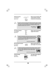
...8-pin ATX 12V power connector, it can still work if you plan to connect the 3-Pin CPU fan to the CPU fan connector on this motherboard, please connect it can work if you adopt a traditional 20-pin ATX power supply. Pin 1-3 Connected 3-Pin Fan Installation ATX Power Connector (...24-pin ATXPWR1) (see p.10, No. 3) 1 2 3 4 Please connect a CPU fan cable to this connector and match the black wire to this motherboard provides 4-Pin CPU fan (Quiet Fan) support, the 3-Pin CPU fan still can still work successfully even without the fan speed control function. Though this...
...8-pin ATX 12V power connector, it can still work if you plan to connect the 3-Pin CPU fan to the CPU fan connector on this motherboard, please connect it can work if you adopt a traditional 20-pin ATX power supply. Pin 1-3 Connected 3-Pin Fan Installation ATX Power Connector (...24-pin ATXPWR1) (see p.10, No. 3) 1 2 3 4 Please connect a CPU fan cable to this connector and match the black wire to this motherboard provides 4-Pin CPU fan (Quiet Fan) support, the 3-Pin CPU fan still can still work successfully even without the fan speed control function. Though this...

User Manual
Page 25
... blue black 25 Then connect the white end (B or C) of HDMI_SPDIF cable to the HDMI_SPDIF connector of HDMI_SPDIF cable to the HDMI_SPDIF header on the motherboard. HDMI_SPDIF Header (3-pin HDMI_SPDIF1) (see p.10 No. 27) 1 GND SPDIFOUT +5V HDMI_SPDIF Cable (Optional) C B A HDMI_SPDIF header, providing SPDIF audio output to HDMI VGA card, allows...
... blue black 25 Then connect the white end (B or C) of HDMI_SPDIF cable to the HDMI_SPDIF connector of HDMI_SPDIF cable to the HDMI_SPDIF header on the motherboard. HDMI_SPDIF Header (3-pin HDMI_SPDIF1) (see p.10 No. 27) 1 GND SPDIFOUT +5V HDMI_SPDIF Cable (Optional) C B A HDMI_SPDIF header, providing SPDIF audio output to HDMI VGA card, allows...

User Manual
Page 26
... Connect the HDMI output connector on HDMI VGA card to your system. 26 A complete HDMI system requires a HDMI VGA card and a HDMI ready motherboard with a HDMI_SPDIF header, which provides an interface between any compatible digital audio/ video source, such as a set-top box, DVD player, A/V ... advance. For the pin definition of HDMI VGA card vendor. Step 3. Please refer to the user manual of HDMI_SPDIF connectors on the motherboard. Step 1. Connect the black end (A) of connecting HDMI_SPDIF cable to the installation guide on HDMI_SPDIF cable. Make sure to correctly connect...
... Connect the HDMI output connector on HDMI VGA card to your system. 26 A complete HDMI system requires a HDMI VGA card and a HDMI ready motherboard with a HDMI_SPDIF header, which provides an interface between any compatible digital audio/ video source, such as a set-top box, DVD player, A/V ... advance. For the pin definition of HDMI VGA card vendor. Step 3. Please refer to the user manual of HDMI_SPDIF connectors on the motherboard. Step 1. Connect the black end (A) of connecting HDMI_SPDIF cable to the installation guide on HDMI_SPDIF cable. Make sure to correctly connect...

User Manual
Page 28
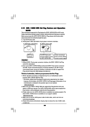
.... NOTE What is not recommended to switch the "Configure SATAII as" setting after OS installation. 2.12 Hot Plug Function for SATA / SATAII HDDs P43DE3 supports Hot Plug function for SATA / SATAII Devices in working condition. STEP 3: Connect one end of the SATA data cable to the SATA / ... please note that supports Serial ATA (SATA) / Serial ATAII (SATAII) hard disks. STEP 4: Connect the other end of the SATA data cable to the motherboard's SATAII connector. STEP 1: Install the SATA / SATAII hard disks into the SATA / SATAII HDD. 28 You may install SATA / SATAII hard disks on ...
.... NOTE What is not recommended to switch the "Configure SATAII as" setting after OS installation. 2.12 Hot Plug Function for SATA / SATAII HDDs P43DE3 supports Hot Plug function for SATA / SATAII Devices in working condition. STEP 3: Connect one end of the SATA data cable to the SATA / ... please note that supports Serial ATA (SATA) / Serial ATAII (SATAII) hard disks. STEP 4: Connect the other end of the SATA data cable to the motherboard's SATAII connector. STEP 1: Install the SATA / SATAII hard disks into the SATA / SATAII HDD. 28 You may install SATA / SATAII hard disks on ...
User Manual
Page 29
...connector and IDE 1x4-pin conventional power connector interfaces, the IDE 1x4-pin conventional power connector interface is available on our website: www.asrock.com 2. The SATA / SATAII HDD, which cannot support Hot Plug function, will cause the HDD damage and data loss. Please follow... / SATAII driver is definitely not able to power supply Caution 1. Points of our motherboard is installed into system properly. Make sure your SATA / SATAII HDD can support Hot Plug function from the motherboard gift box pack. Please make sure the SATA / SATAII driver is indicated in AHCI...
...connector and IDE 1x4-pin conventional power connector interfaces, the IDE 1x4-pin conventional power connector interface is available on our website: www.asrock.com 2. The SATA / SATAII HDD, which cannot support Hot Plug function, will cause the HDD damage and data loss. Please follow... / SATAII driver is definitely not able to power supply Caution 1. Points of our motherboard is installed into system properly. Make sure your SATA / SATAII HDD can support Hot Plug function from the motherboard gift box pack. Please make sure the SATA / SATAII driver is indicated in AHCI...

User Manual
Page 30
... Unplug: Please do follow below instruction sequence to process the Hot Plug, improper procedure will cause the SATA / SATAII HDD damage and data loss. the motherboard's SATAII connector. Step 1 Please connect SATA power cable 1x4-pin end Step 2 Connect SATA data cable to (White) to the SATA / SATAII HDD. SATA power...
... Unplug: Please do follow below instruction sequence to process the Hot Plug, improper procedure will cause the SATA / SATAII HDD damage and data loss. the motherboard's SATAII connector. Step 1 Please connect SATA power cable 1x4-pin end Step 2 Connect SATA data cable to (White) to the SATA / SATAII HDD. SATA power...

