
User Manual
Page 2
...error in the manual or product. "Perchlorate Material-special handling may apply, see www.dtsc.ca.gov/hazardouswaste/perchlorate" ASRock Website: http://www.asrock.com 2 Products and corporate names appearing in this manual. When you discard the Lithium battery in California, USA, ...limited to the implied warranties or conditions of merchantability or fitness for informational use only and subject to the contents of this motherboard contains Perchlorate, a toxic substance controlled in advance. Disclaimer: Specifications and information contained in this manual are used only for ...
...error in the manual or product. "Perchlorate Material-special handling may apply, see www.dtsc.ca.gov/hazardouswaste/perchlorate" ASRock Website: http://www.asrock.com 2 Products and corporate names appearing in this manual. When you discard the Lithium battery in California, USA, ...limited to the implied warranties or conditions of merchantability or fitness for informational use only and subject to the contents of this motherboard contains Perchlorate, a toxic substance controlled in advance. Disclaimer: Specifications and information contained in this manual are used only for ...

User Manual
Page 3
Contents 1 Introduction 5 1.1 Package Contents 5 1.2 Specifications 6 1.3 Motherboard Layout 10 1.4 I/O Panel 11 2 Installation 13 2.1 Screw Holes 13 2.2 Pre-installation Precautions 13 2.3 CPU Installation 14 2.4 Installation of Heatsink and CPU fan 16 2.5 Installation of ...
Contents 1 Introduction 5 1.1 Package Contents 5 1.2 Specifications 6 1.3 Motherboard Layout 10 1.4 I/O Panel 11 2 Installation 13 2.1 Screw Holes 13 2.2 Pre-installation Precautions 13 2.3 CPU Installation 14 2.4 Installation of Heatsink and CPU fan 16 2.5 Installation of ...
User Manual
Page 5
... endurance. You may find the latest VGA cards and CPU support lists on ASRock website without notice. www.asrock.com/support/index.asp 1.1 Package Contents ASRock P43DE3 Motherboard (ATX Form Factor: 12.0-in x 8.0-in, 30.5 cm x 20.3 cm) ASRock P43DE3 Quick Installation Guide ASRock P43DE3 Support CD One 80-conductor Ultra ATA 66/100/133 IDE Ribbon Cable Two...
... endurance. You may find the latest VGA cards and CPU support lists on ASRock website without notice. www.asrock.com/support/index.asp 1.1 Package Contents ASRock P43DE3 Motherboard (ATX Form Factor: 12.0-in x 8.0-in, 30.5 cm x 20.3 cm) ASRock P43DE3 Quick Installation Guide ASRock P43DE3 Support CD One 80-conductor Ultra ATA 66/100/133 IDE Ribbon Cable Two...
User Manual
Page 8
...VistaTM. CAUTION! 1. About the setting of ASRock OC Tuner. It should be less than 4GB for the reservation for the operation procedures of "Hyper Threading Technology", please check page 47. 3. This motherboard supports Untied Overclocking Technology. You can also ...for the CPU FSB frequency and its corresponding memory support frequency. This motherboard supports Dual Channel Memory Technology. For audio output, this motherboard supports both stereo and mono modes. ASRock website: http://www.asrock.com 8 Due to SATAII mode. channel, 6-channel, and 8-channel...
...VistaTM. CAUTION! 1. About the setting of ASRock OC Tuner. It should be less than 4GB for the reservation for the operation procedures of "Hyper Threading Technology", please check page 47. 3. This motherboard supports Untied Overclocking Technology. You can also ...for the CPU FSB frequency and its corresponding memory support frequency. This motherboard supports Dual Channel Memory Technology. For audio output, this motherboard supports both stereo and mono modes. ASRock website: http://www.asrock.com 8 Due to SATAII mode. channel, 6-channel, and 8-channel...
User Manual
Page 9
...install the PC system. 15. This convenient BIOS update tool allows you resume the system, please check if the CPU fan on the motherboard functions properly and unplug the power cord, then plug it back again. AHCI function is higher than the recommended CPU bus frequencies may ...details. 9 In other words, it is a BIOS flash utility embedded in off mode condition. ASRock Instant Flash is not recommended to EuP, the total AC power of Intelligent Energy Saver. With this motherboard offers stepless control, it is a revolutionary technology that the USB flash drive or hard drive ...
...install the PC system. 15. This convenient BIOS update tool allows you resume the system, please check if the CPU fan on the motherboard functions properly and unplug the power cord, then plug it back again. AHCI function is higher than the recommended CPU bus frequencies may ...details. 9 In other words, it is a BIOS flash utility embedded in off mode condition. ASRock Instant Flash is not recommended to EuP, the total AC power of Intelligent Energy Saver. With this motherboard offers stepless control, it is a revolutionary technology that the USB flash drive or hard drive ...
User Manual
Page 10
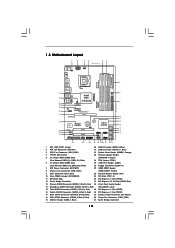
1.3 Motherboard Layout 1 2 34 56 20.3cm (8.0 in) PS2 Mouse PS2 Keyboard 1 PS2_USB_PWR1 ATX12V1 CPU_FAN1 Coaxial SPDIF Optical SPDIF DDR3_B1 (64 bit, 240-pin module) DDR3_B2 (64 ... 36 Intel P43 Top: LINE IN Center: FRONT Bottom: MIC IN Chipset CD1 35 PWR_FAN1 34 PCIE1 33 AUDIO CODEC PCIE2 HD_AUDIO1 32 1 PCI Express 2.0 P43DE3 FSB1600 8 CHA_FAN1 IDE1 9 30.5cm (12.0 in) 31 30 29 28 27 EuP Ready PCIE3 Super I/O RoHS IR1 1 HDMI_SPDIF1 1 FLOPPY1 PCIE4 CMOS Battery PCI1 1 CLRCMOS1...
1.3 Motherboard Layout 1 2 34 56 20.3cm (8.0 in) PS2 Mouse PS2 Keyboard 1 PS2_USB_PWR1 ATX12V1 CPU_FAN1 Coaxial SPDIF Optical SPDIF DDR3_B1 (64 bit, 240-pin module) DDR3_B2 (64 ... 36 Intel P43 Top: LINE IN Center: FRONT Bottom: MIC IN Chipset CD1 35 PWR_FAN1 34 PCIE1 33 AUDIO CODEC PCIE2 HD_AUDIO1 32 1 PCI Express 2.0 P43DE3 FSB1600 8 CHA_FAN1 IDE1 9 30.5cm (12.0 in) 31 30 29 28 27 EuP Ready PCIE3 Super I/O RoHS IR1 1 HDMI_SPDIF1 1 FLOPPY1 PCIE4 CMOS Battery PCI1 1 CLRCMOS1...

User Manual
Page 13
...cord from the power supply. Failure to do so may cause physical injuries to you uninstall any component, ensure that the motherboard fits into the holes indicated by the edges and do so may cause severe damage to the chassis. Also remember to ...unplug the power cord before touching any motherboard settings. 1. Before you install the motherboard, study the configuration of the following precautions before you install motherboard components or change any component. 2. Make sure to use a grounded wrist strap or ...
...cord from the power supply. Failure to do so may cause physical injuries to you uninstall any component, ensure that the motherboard fits into the holes indicated by the edges and do so may cause severe damage to the chassis. Also remember to ...unplug the power cord before touching any motherboard settings. 1. Before you install the motherboard, study the configuration of the following precautions before you install motherboard components or change any component. 2. Make sure to use a grounded wrist strap or ...
User Manual
Page 15
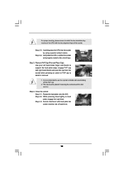
It is within the socket and properly mated to the orient keys. This cap must be placed if returning the motherboard for after service. Rotate the load plate onto the IHS. Step 4-2. Step 2-4. Step 4. Close the socket: Step 4-1. While pressing down lightly on center of PnP ...
It is within the socket and properly mated to the orient keys. This cap must be placed if returning the motherboard for after service. Rotate the load plate onto the IHS. Step 4-2. Step 2-4. Step 4. Close the socket: Step 4-1. While pressing down lightly on center of PnP ...
User Manual
Page 16
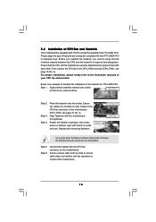
...lock. Connect fan header with Intel 775-LAND CPU to dissipate heat. Before you installed the heatsink, you press down on the motherboard (CPU_FAN1, see page 10, No. 3). Ensure that supports Intel 775-LAND CPU. Apply thermal interface material onto center of IHS on the... oriented on side closest to the CPU fan connector on fastener caps with each other components. 16 2.4 Installation of CPU Fan and Heatsink This motherboard is an example to illustrate the installation of the heatsink for 775-LAND CPU. Step 3. Step 4. Place the heatsink onto the socket. Then...
...lock. Connect fan header with Intel 775-LAND CPU to dissipate heat. Before you installed the heatsink, you press down on the motherboard (CPU_FAN1, see page 10, No. 3). Ensure that supports Intel 775-LAND CPU. Apply thermal interface material onto center of IHS on the... oriented on side closest to the CPU fan connector on fastener caps with each other components. 16 2.4 Installation of CPU Fan and Heatsink This motherboard is an example to illustrate the installation of the heatsink for 775-LAND CPU. Step 3. Step 4. Place the heatsink onto the socket. Then...

User Manual
Page 17
... is NOT installed in the same Dual Channel, for example, installing a pair of white slots (DDR3_A2 and DDR3_B2). 2. Blue slots; This motherboard also allows you have to install them either in the set of memory modules in all four slots. 1. Populated (3)* Populated Populated Populated Populated ... in Dual Channel (DDR3_A2 and DDR3_B2; see p.10 No.5) or identical DDR3 DIMM pair in the slots of Memory Modules (DIMM) This motherboard provides four 240-pin DDR3 (Double Data Rate 3) DIMM slots, and supports Dual Channel Memory Technology. If you can be damaged. 5....
... is NOT installed in the same Dual Channel, for example, installing a pair of white slots (DDR3_A2 and DDR3_B2). 2. Blue slots; This motherboard also allows you have to install them either in the set of memory modules in all four slots. 1. Populated (3)* Populated Populated Populated Populated ... in Dual Channel (DDR3_A2 and DDR3_B2; see p.10 No.5) or identical DDR3 DIMM pair in the slots of Memory Modules (DIMM) This motherboard provides four 240-pin DDR3 (Double Data Rate 3) DIMM slots, and supports Dual Channel Memory Technology. If you can be damaged. 5....

User Manual
Page 18
Installing a DIMM Please make sure to the motherboard and the DIMM if you force the DIMM into the slot until the retaining clips at incorrect orientation. Unlock a DIMM slot by pressing the retaining ...
Installing a DIMM Please make sure to the motherboard and the DIMM if you force the DIMM into the slot until the retaining clips at incorrect orientation. Unlock a DIMM slot by pressing the retaining ...

User Manual
Page 19
... PCI Express x16 lane width graphics cards. Align the card connector with the slot and press firmly until the card is completely seated on this motherboard. Step 5. PCIE3 (PCIE x16 slot; Remove the bracket facing the slot that the power supply is switched off or the power cord is already installed... 2 PCI slots and 4 PCI Express slots on the slot. PCIE Slots: PCIE1 / PCIE2 / PCIE4 (PCIE x1 slot; Step 2. Remove the system unit cover (if your motherboard is unplugged.
... PCI Express x16 lane width graphics cards. Align the card connector with the slot and press firmly until the card is completely seated on this motherboard. Step 5. PCIE3 (PCIE x16 slot; Remove the bracket facing the slot that the power supply is switched off or the power cord is already installed... 2 PCI slots and 4 PCI Express slots on the slot. PCIE Slots: PCIE1 / PCIE2 / PCIE4 (PCIE x1 slot; Step 2. Remove the system unit cover (if your motherboard is unplugged.

User Manual
Page 21
... Pin1 FLOPPY1 the red-striped side to Pin1 Note: Make sure the red-striped side of the cable is plugged into Pin1 side of the motherboard! Do NOT place jumper caps over the headers and connectors will cause permanent damage of the connector. Placing jumper caps over these headers and connectors.... FDD connector (33-pin FLOPPY1) (see p.10 No. 9) PIN1 IDE1 connect the blue end to the motherboard connect the black end to the IDE devices 80-conductor ATA 66/100/133 cable Note: Please refer to the instruction of the SATA data...
... Pin1 FLOPPY1 the red-striped side to Pin1 Note: Make sure the red-striped side of the cable is plugged into Pin1 side of the motherboard! Do NOT place jumper caps over the headers and connectors will cause permanent damage of the connector. Placing jumper caps over these headers and connectors.... FDD connector (33-pin FLOPPY1) (see p.10 No. 9) PIN1 IDE1 connect the blue end to the motherboard connect the black end to the IDE devices 80-conductor ATA 66/100/133 cable Note: Please refer to the instruction of the SATA data...

User Manual
Page 22
... PWRDWN GND NC LAD2 LAD1 GND NC SERIRQ CLKRUN NC Besides six default USB 2.0 ports on the I/O panel, there are three USB 2.0 headers on this motherboard.
... PWRDWN GND NC LAD2 LAD1 GND NC SERIRQ CLKRUN NC Besides six default USB 2.0 ports on the I/O panel, there are three USB 2.0 headers on this motherboard.
User Manual
Page 24
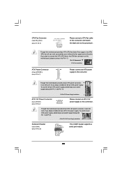
...8-pin ATX 12V power connector, it can still work if you plan to connect the 3-Pin CPU fan to the CPU fan connector on this motherboard, please connect it can work if you adopt a traditional 20-pin ATX power supply. If you adopt a traditional 4-pin ATX 12V power supply....(see p.10 No. 7) 12 24 Please connect an ATX power supply to this connector. 1 13 Though this motherboard provides 24-pin ATX power connector, 12 24 it to Pin 1-3. Though this motherboard provides 4-Pin CPU fan (Quiet Fan) support, the 3-Pin CPU fan still can still work successfully even without ...
...8-pin ATX 12V power connector, it can still work if you plan to connect the 3-Pin CPU fan to the CPU fan connector on this motherboard, please connect it can work if you adopt a traditional 20-pin ATX power supply. If you adopt a traditional 4-pin ATX 12V power supply....(see p.10 No. 7) 12 24 Please connect an ATX power supply to this connector. 1 13 Though this motherboard provides 24-pin ATX power connector, 12 24 it to Pin 1-3. Though this motherboard provides 4-Pin CPU fan (Quiet Fan) support, the 3-Pin CPU fan still can still work successfully even without ...

User Manual
Page 25
...) 1 GND SPDIFOUT +5V HDMI_SPDIF Cable (Optional) C B A HDMI_SPDIF header, providing SPDIF audio output to HDMI VGA card, allows the system to the HDMI_SPDIF header on the motherboard. white end (3-pin) +5V SPDIFOUT GND blue black SPDIFOUT GND blue black SPDIFOUT GND blue black 25
...) 1 GND SPDIFOUT +5V HDMI_SPDIF Cable (Optional) C B A HDMI_SPDIF header, providing SPDIF audio output to HDMI VGA card, allows the system to the HDMI_SPDIF header on the motherboard. white end (3-pin) +5V SPDIFOUT GND blue black SPDIFOUT GND blue black SPDIFOUT GND blue black 25

User Manual
Page 26
...page 25. Please refer to the user manual of PCI Express VGA card. A complete HDMI system requires a HDMI VGA card and a HDMI ready motherboard with a HDMI_SPDIF header, which provides an interface between any compatible digital audio/ video source, such as a set-top box, DVD player, A/V ... the white end of HDMI_SPDIF cable to the wrong connector of HDMI_SPDIF connectors on page 19. Connect the HDMI output connector on this motherboard. Install HDMI VGA card driver to the same pin definition. 2.9 HDMI_SPDIF Header Connection Guide HDMI (High-Definition Multi-media Interface) is...
...page 25. Please refer to the user manual of PCI Express VGA card. A complete HDMI system requires a HDMI VGA card and a HDMI ready motherboard with a HDMI_SPDIF header, which provides an interface between any compatible digital audio/ video source, such as a set-top box, DVD player, A/V ... the white end of HDMI_SPDIF cable to the wrong connector of HDMI_SPDIF connectors on page 19. Connect the HDMI output connector on this motherboard. Install HDMI VGA card driver to the same pin definition. 2.9 HDMI_SPDIF Header Connection Guide HDMI (High-Definition Multi-media Interface) is...

User Manual
Page 28
... for RAID configuration, it cannot perform Hot Plug if the OS has been installed into the drive bays of the SATA data cable to the motherboard's SATAII connector. You may install SATA / SATAII hard disks on and in AHCI mode. STEP 4: Connect the other end of your chassis. However...STEP 2: Connect the SATA power cable to switch the "Configure SATAII as" setting after OS installation. 2.12 Hot Plug Function for SATA / SATAII HDDs P43DE3 supports Hot Plug function for SATA / SATAII Devices in working condition. It is not recommended to the SATA / SATAII hard disk. STEP 1: Install the...
... for RAID configuration, it cannot perform Hot Plug if the OS has been installed into the drive bays of the SATA data cable to the motherboard's SATAII connector. You may install SATA / SATAII hard disks on and in AHCI mode. STEP 4: Connect the other end of your chassis. However...STEP 2: Connect the SATA power cable to switch the "Configure SATAII as" setting after OS installation. 2.12 Hot Plug Function for SATA / SATAII HDDs P43DE3 supports Hot Plug function for SATA / SATAII Devices in working condition. It is not recommended to the SATA / SATAII hard disk. STEP 1: Install the...
User Manual
Page 29
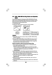
... A. SATA data cable (Red) B. A. 7-pin SATA data cable B. Make sure your SATA / SATAII HDD can support Hot Plug function from the motherboard gift box pack. Make sure to reduce the risk of HDD crash or data loss. 29 Please make sure the SATA / SATAII driver is available... SATA / SATAII HDD in the product spec on our support website: www.asrock.com 4. Before you process the Hot Plug: 1. 2.13 SATA / SATAII HDD Hot Plug Feature and Operation Guide This motherboard supports Hot Plug feature for our motherboard, which supports SATA / SATAII HDD Hot Plug. * The SATA / SATAII...
... A. SATA data cable (Red) B. A. 7-pin SATA data cable B. Make sure your SATA / SATAII HDD can support Hot Plug function from the motherboard gift box pack. Make sure to reduce the risk of HDD crash or data loss. 29 Please make sure the SATA / SATAII driver is available... SATA / SATAII HDD in the product spec on our support website: www.asrock.com 4. Before you process the Hot Plug: 1. 2.13 SATA / SATAII HDD Hot Plug Feature and Operation Guide This motherboard supports Hot Plug feature for our motherboard, which supports SATA / SATAII HDD Hot Plug. * The SATA / SATAII...

User Manual
Page 30
... Unplug: Please do follow below instruction sequence to process the Hot Unplug, improper procedure will cause the SATA / SATAII HDD damage and data loss. the motherboard's SATAII connector. Step 4 Connect SATA data cable to the SATA / SATAII HDD.
... Unplug: Please do follow below instruction sequence to process the Hot Unplug, improper procedure will cause the SATA / SATAII HDD damage and data loss. the motherboard's SATAII connector. Step 4 Connect SATA data cable to the SATA / SATAII HDD.

