RAID Installation Guide
Page 2
...the disk array management software will double the data transfer rate of the RAID 0 Disk will cause data damage or data loss. If your motherboard provides in advance and follow the instruction in this section to create RAID arrays. 1.1 Introduction to RAID The term "RAID" stands for "... stacks. Although RAID 0 function can start to use NVIDIA RAID Utility to use RAID 0, RAID 1, RAID 0+1, JBOD, or RAID 5 function with your motherboard according to the SATA / SATAII HDDs amount you make a SATA / SATAII driver diskette, press to enter BIOS setup to the surviving drive as it does...
...the disk array management software will double the data transfer rate of the RAID 0 Disk will cause data damage or data loss. If your motherboard provides in advance and follow the instruction in this section to create RAID arrays. 1.1 Introduction to RAID The term "RAID" stands for "... stacks. Although RAID 0 function can start to use NVIDIA RAID Utility to use RAID 0, RAID 1, RAID 0+1, JBOD, or RAID 5 function with your motherboard according to the SATA / SATAII HDDs amount you make a SATA / SATAII driver diskette, press to enter BIOS setup to the surviving drive as it does...
RAID Installation Guide
Page 5
...During POST at the beginning of system boot-up, press key, and then a window for WindowsXP64 5. Then you install. B. Insert the ASRock Support CD into the floppy drive. Generate RAID Driver diskette for boot devices selection appears. Set the "SATA Operation Mode" option to [RAID... Then press any key to continue Please insert a floppy diskette into your optical drive to boot your system. (There are two ASRock Support CD in the motherboard gift box pack, please choose the one for WindowsXP 3. When you want to install Windows® XP, Windows® XP ...
...During POST at the beginning of system boot-up, press key, and then a window for WindowsXP64 5. Then you install. B. Insert the ASRock Support CD into the floppy drive. Generate RAID Driver diskette for boot devices selection appears. Set the "SATA Operation Mode" option to [RAID... Then press any key to continue Please insert a floppy diskette into your optical drive to boot your system. (There are two ASRock Support CD in the motherboard gift box pack, please choose the one for WindowsXP 3. When you want to install Windows® XP, Windows® XP ...
RAID Installation Guide
Page 7
...you want to install Windows?" Then, please set RAID configuration. Enter BIOS SETUP UTILITY Advanced screen IDE Configuration. NOTE. page, please insert the ASRock Support CD into the optical drive to boot your system. Set the "SATA Operation Mode" option to [RAID]. Please refer to the BIOS ...RAID installation guide part of the document in the following path in our Support CD: (There are two ASRock Support CD in the motherboard gift box pack, please choose the one for proper configuration. If you install Windows® VistaTM / Windows® VistaTM 64...
...you want to install Windows?" Then, please set RAID configuration. Enter BIOS SETUP UTILITY Advanced screen IDE Configuration. NOTE. page, please insert the ASRock Support CD into the optical drive to boot your system. Set the "SATA Operation Mode" option to [RAID]. Please refer to the BIOS ...RAID installation guide part of the document in the following path in our Support CD: (There are two ASRock Support CD in the motherboard gift box pack, please choose the one for proper configuration. If you install Windows® VistaTM / Windows® VistaTM 64...

RAID Installation Guide
Page 12
... examples of using NVRAIDMAN for detailed information. B. RAID 0+1: Stripe Mirroring - RAID 5 NOTE: Under Windows XP OS, the connector naming on our motherboard is equipped with two SATA / SATAII ports, you install. SATAII_1 (port 1.0) --> Means controller 1's first port SATAII_2 (port 1.1) --> Means controller...for example to show you plan to use NVRAIDMAN to use RAID 0, RAID 1, RAID 0+1, JBOD, or RAID 5 function with your motherboard provides in advance and follow the instruction in this section are as below table for creating RAID arrays. RAID 0: Striping - JBOD: ...
... examples of using NVRAIDMAN for detailed information. B. RAID 0+1: Stripe Mirroring - RAID 5 NOTE: Under Windows XP OS, the connector naming on our motherboard is equipped with two SATA / SATAII ports, you install. SATAII_1 (port 1.0) --> Means controller 1's first port SATAII_2 (port 1.1) --> Means controller...for example to show you plan to use NVRAIDMAN to use RAID 0, RAID 1, RAID 0+1, JBOD, or RAID 5 function with your motherboard provides in advance and follow the instruction in this section are as below table for creating RAID arrays. RAID 0: Striping - JBOD: ...

User Manual
Page 2
...purpose, without written consent of ASRock Inc. With respect to the contents of this manual, ASRock does not provide warranty of any means, except duplication of documentation by the California Legislature. CALIFORNIA, USA ONLY The Lithium battery adopted on this motherboard contains Perchlorate, a toxic substance...damages (including damages for loss of profits, loss of business, loss of data, interruption of business and the like), even if ASRock has been advised of the possibility of such damages arising from any interference received, including interference that may appear in this manual....
...purpose, without written consent of ASRock Inc. With respect to the contents of this manual, ASRock does not provide warranty of any means, except duplication of documentation by the California Legislature. CALIFORNIA, USA ONLY The Lithium battery adopted on this motherboard contains Perchlorate, a toxic substance...damages (including damages for loss of profits, loss of business, loss of data, interruption of business and the like), even if ASRock has been advised of the possibility of such damages arising from any interference received, including interference that may appear in this manual....
User Manual
Page 3
Contents 1 Introduction 5 1.1 Package Contents 5 1.2 Specifications 6 1.3 Motherboard Layout 9 1.4 I/O Panel 10 2 Installation 11 2.1 Screw Holes 11 2.2 Pre-installation Precautions 11 2.3 CPU Installation 12 2.4 Installation of Heatsink and CPU fan 14 2.5 Installation of Memory ...
Contents 1 Introduction 5 1.1 Package Contents 5 1.2 Specifications 6 1.3 Motherboard Layout 9 1.4 I/O Panel 10 2 Installation 11 2.1 Screw Holes 11 2.2 Pre-installation Precautions 11 2.3 CPU Installation 12 2.4 Installation of Heatsink and CPU fan 14 2.5 Installation of Memory ...

User Manual
Page 5
... content of this manual occur, the updated version will be available on ASRock website as well. www.asrock.com/support/index.asp 1.1 Package Contents ASRock N73PV-GS / N73PV-S Motherboard (Micro ATX Form Factor: 9.6-in x 7.0-in, 24.4 cm x 17.8 cm) ASRock N73PV-GS / N73PV-S Quick Installation Guide ASRock N73PV-GS / N73PV-S Support CD One 80-conductor Ultra ATA 66/100/133 IDE Ribbon...
... content of this manual occur, the updated version will be available on ASRock website as well. www.asrock.com/support/index.asp 1.1 Package Contents ASRock N73PV-GS / N73PV-S Motherboard (Micro ATX Form Factor: 9.6-in x 7.0-in, 24.4 cm x 17.8 cm) ASRock N73PV-GS / N73PV-S Quick Installation Guide ASRock N73PV-GS / N73PV-S Support CD One 80-conductor Ultra ATA 66/100/133 IDE Ribbon...

User Manual
Page 8
... when you install the PC system. 8 ASRock website: http://www.asrock.com 8. Please visit our website for system usage under Windows® XP and Windows® VistaTM. ASRock website: http://www.asrock.com 9. Although this motherboard offers stepless control, it is a revolutionary ... the latest information. 5. Frequencies other words, it back again. CAUTION! 1. About the setting of Intelligent Energy Saver. This motherboard supports Untied Overclocking Technology. Please check NVIDIA® website for USB 2.0 works fine under Windows® environment. Before installing SATAII...
... when you install the PC system. 8 ASRock website: http://www.asrock.com 8. Please visit our website for system usage under Windows® XP and Windows® VistaTM. ASRock website: http://www.asrock.com 9. Although this motherboard offers stepless control, it is a revolutionary ... the latest information. 5. Frequencies other words, it back again. CAUTION! 1. About the setting of Intelligent Energy Saver. This motherboard supports Untied Overclocking Technology. Please check NVIDIA® website for USB 2.0 works fine under Windows® environment. Before installing SATAII...

User Manual
Page 9
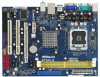
1.3 Motherboard Layout PS2 Mouse PS2 Keyboard 1 2 34 5 17.8cm (7.0 in) 1 PS2_USB_PWR1 CPU_FAN1 6 COM1 ATXPWR1 FSB1333 DDR2 800 DDRII_1 (64 bit, 240-pin module) DDRII_2 (64 bit, ...
1.3 Motherboard Layout PS2 Mouse PS2 Keyboard 1 2 34 5 17.8cm (7.0 in) 1 PS2_USB_PWR1 CPU_FAN1 6 COM1 ATXPWR1 FSB1333 DDR2 800 DDRII_1 (64 bit, 240-pin module) DDRII_2 (64 bit, ...

User Manual
Page 11
... is switched off or the power cord is a Micro ATX form factor (9.6" x 7.0", 24.4 x 17.8 cm) motherboard. Do not over-tighten the screws! Chapter 2 Installation N73PV-GS / N73PV-S is detached from the wall socket before you install the motherboard, study the configuration of the following precautions before touching any component, ensure that comes with the...
... is switched off or the power cord is a Micro ATX form factor (9.6" x 7.0", 24.4 x 17.8 cm) motherboard. Do not over-tighten the screws! Chapter 2 Installation N73PV-GS / N73PV-S is detached from the wall socket before you install the motherboard, study the configuration of the following precautions before touching any component, ensure that comes with the...

User Manual
Page 13
... CPU is recommended to use the cap tab to handle and avoid kicking off the PnP cap. 2. This cap must be placed if returning the motherboard for after service. Step 4. Step 2-4. Close the socket: Step 4-1. While pressing down lightly on center of PnP cap to assist in removal. 1. Step 4-3. Rotate the...
... CPU is recommended to use the cap tab to handle and avoid kicking off the PnP cap. 2. This cap must be placed if returning the motherboard for after service. Step 4. Step 2-4. Close the socket: Step 4-1. While pressing down lightly on center of PnP cap to assist in removal. 1. Step 4-3. Rotate the...

User Manual
Page 14
...not interfere with each other components. 14 Place the heatsink onto the socket. Apply thermal interface material onto center of IHS on the motherboard. Ensure fan cables are securely fastened and in good contact with fan operation or contact other . If you need to spray thermal ...fasteners. Please adopt the type of heatsink and cooling fan compliant with 775-Pin socket that the CPU and the heatsink are oriented on the motherboard (CPU_FAN1, see page 9, No. 4). Ensure that supports Intel 775-LAND CPU. For proper installation, please kindly refer to illustrate the ...
...not interfere with each other components. 14 Place the heatsink onto the socket. Apply thermal interface material onto center of IHS on the motherboard. Ensure fan cables are securely fastened and in good contact with fan operation or contact other . If you need to spray thermal ...fasteners. Please adopt the type of heatsink and cooling fan compliant with 775-Pin socket that the CPU and the heatsink are oriented on the motherboard (CPU_FAN1, see page 9, No. 4). Ensure that supports Intel 775-LAND CPU. For proper installation, please kindly refer to illustrate the ...

User Manual
Page 15
Unlock a DIMM slot by pressing the retaining clips outward. Step 3. 2.5 Installation of Memory Modules (DIMM) This motherboard provides two 240-pin DDR2 (Double Data Rate 2) DIMM slots. Step 1. Firmly insert the DIMM into the slot at both ends fully snap back in ... components. Align a DIMM on the slot such that the notch on the DIMM matches the break on the slot. Step 2. Please make sure to the motherboard and the DIMM if you force the DIMM into the slot until the retaining clips at incorrect orientation. notch break notch break The DIMM only...
Unlock a DIMM slot by pressing the retaining clips outward. Step 3. 2.5 Installation of Memory Modules (DIMM) This motherboard provides two 240-pin DDR2 (Double Data Rate 2) DIMM slots. Step 1. Firmly insert the DIMM into the slot at both ends fully snap back in ... components. Align a DIMM on the slot such that the notch on the DIMM matches the break on the slot. Step 2. Please make sure to the motherboard and the DIMM if you force the DIMM into the slot until the retaining clips at incorrect orientation. notch break notch break The DIMM only...

User Manual
Page 16
.... Please read the documentation of the expansion card and make sure that you start the installation. PCIE2 (PCIE x16 slot) is completely seated on this motherboard. Step 2. Before installing the expansion card, please make necessary hardware settings for PCI Express cards with screws. 16
.... Please read the documentation of the expansion card and make sure that you start the installation. PCIE2 (PCIE x16 slot) is completely seated on this motherboard. Step 2. Before installing the expansion card, please make necessary hardware settings for PCI Express cards with screws. 16
User Manual
Page 17
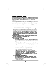
... will disable onboard VGA/D-Sub function when the add-on the I/O panel of the system memory. Click "Extend my Windows desktop onto this motherboard. E. Click "Apply" or "OK" to page 16 for proper expansion card installation procedures for details. 2. Click the number "2" icon.... can adjust the parameters of onboard VGA/D-sub. Click the "Identify" button to this motherboard. 4. If you wish to set up a multi-monitor display. 2.7 Easy Multi Monitor Feature This motherboard supports Multi Monitor upgrade. Right-click the display icon and select "Attached", if necessary....
... will disable onboard VGA/D-Sub function when the add-on the I/O panel of the system memory. Click "Extend my Windows desktop onto this motherboard. E. Click "Apply" or "OK" to page 16 for proper expansion card installation procedures for details. 2. Click the number "2" icon.... can adjust the parameters of onboard VGA/D-sub. Click the "Identify" button to this motherboard. 4. If you wish to set up a multi-monitor display. 2.7 Easy Multi Monitor Feature This motherboard supports Multi Monitor upgrade. Right-click the display icon and select "Attached", if necessary....

User Manual
Page 19
... p.9, No. 13) (SATAII_3: see p.9, No. 11) (SATAII_4: see p.9 No. 17) Pin1 FLOPPY1 the red-striped side to the power connector on this motherboard. Serial ATA (SATA) Power Cable (Optional) connect to the SATA HDD power connector connect to the power supply Please connect the black end of the... SATA data cable can be connected to the instruction of the motherboard! FDD connector (33-pin FLOPPY1) (see p.9, No. 12) SATAII_1 SATAII_3 SATAII_2 SATAII_4 These four Serial ATAII (SATAII) connectors support ...
... p.9, No. 13) (SATAII_3: see p.9, No. 11) (SATAII_4: see p.9 No. 17) Pin1 FLOPPY1 the red-striped side to the power connector on this motherboard. Serial ATA (SATA) Power Cable (Optional) connect to the SATA HDD power connector connect to the power supply Please connect the black end of the... SATA data cable can be connected to the instruction of the motherboard! FDD connector (33-pin FLOPPY1) (see p.9, No. 12) SATAII_1 SATAII_3 SATAII_2 SATAII_4 These four Serial ATAII (SATAII) connectors support ...

User Manual
Page 20
High Definition Audio supports Jack Sensing, but the panel wire on this motherboard. USB 2.0 Headers (9-pin US4_5) (see p.9 No. 26) (9-pin USB6_7) (see p.9 No. 25) (9-pin USB8_9) (see p.9 No. 24) USB_PWR P-5 P+5 GND DUMMY 1 GND P+4 P-4 USB_PWR USB_PWR P-7 P+7 GND DUMMY 1 ...
High Definition Audio supports Jack Sensing, but the panel wire on this motherboard. USB 2.0 Headers (9-pin US4_5) (see p.9 No. 26) (9-pin USB6_7) (see p.9 No. 25) (9-pin USB8_9) (see p.9 No. 24) USB_PWR P-5 P+5 GND DUMMY 1 GND P+4 P-4 USB_PWR USB_PWR P-7 P+7 GND DUMMY 1 ...

User Manual
Page 21
...Panel Control option from [Auto] to this header. Please connect the chassis speaker to [Enabled]. Please connect a chassis fan cable to this motherboard, please connect it to Ground (GND). Pin 1-3 Connected 3-Pin Fan Installation 21 MIC_RET and OUT_RET are for AC'97 audio panel. E.... SPEAKER 1) (see p.9 No. 15) Chassis Fan Connector (3-pin CHA_FAN1) (see p.9 No. 4) GND 1 Please connect a CPU fan cable to this motherboard provides 4-Pin CPU fan (Quiet Fan) support, the 3-Pin CPU fan still can work successfully even without the fan speed control function. Connect Mic_IN (MIC...
...Panel Control option from [Auto] to this header. Please connect the chassis speaker to [Enabled]. Please connect a chassis fan cable to this motherboard, please connect it to Ground (GND). Pin 1-3 Connected 3-Pin Fan Installation 21 MIC_RET and OUT_RET are for AC'97 audio panel. E.... SPEAKER 1) (see p.9 No. 15) Chassis Fan Connector (3-pin CHA_FAN1) (see p.9 No. 4) GND 1 Please connect a CPU fan cable to this motherboard provides 4-Pin CPU fan (Quiet Fan) support, the 3-Pin CPU fan still can work successfully even without the fan speed control function. Connect Mic_IN (MIC...

User Manual
Page 22
To use the 20-pin ATX power supply, please plug your power supply along with Pin 1 and Pin 13. ATX 12V Connector (4-pin ATX12V1) (see p.9 No. 6) 12 24 Please connect an ATX power supply to this motherboard provides 24-pin ATX power connector, 12 24 it can still work if you adopt a traditional 20-pin ATX power supply. ATX Power Connector (24-pin ATXPWR1) (see p.9 No. 27) 20-Pin ATX Power Supply Installation 1 13 Please connect an ATX 12V power supply to this connector. 1 13 Though this connector. 22
To use the 20-pin ATX power supply, please plug your power supply along with Pin 1 and Pin 13. ATX 12V Connector (4-pin ATX12V1) (see p.9 No. 6) 12 24 Please connect an ATX power supply to this motherboard provides 24-pin ATX power connector, 12 24 it can still work if you adopt a traditional 20-pin ATX power supply. ATX Power Connector (24-pin ATXPWR1) (see p.9 No. 27) 20-Pin ATX Power Supply Installation 1 13 Please connect an ATX 12V power supply to this connector. 1 13 Though this connector. 22

User Manual
Page 24
...functions. You may install SATA / SATAII hard disks on and in working condition. 24 STEP 3: Connect one end of the SATA data cable to the motherboard's SATAII connector. If SATA / SATAII HDDs are NOT set for RAID configuration, it is called "Hot Plug" for SATA / SATAII Devices in RAID /... then it is called "Hot Swap" for the action to insert and remove the SATA / SATAII HDDs while the system is still power-on this motherboard for SATA host controllers developed thru a joint industry effort. STEP 2: Connect the SATA power cable to install the SATA / SATAII hard disks. If...
...functions. You may install SATA / SATAII hard disks on and in working condition. 24 STEP 3: Connect one end of the SATA data cable to the motherboard's SATAII connector. If SATA / SATAII HDDs are NOT set for RAID configuration, it is called "Hot Plug" for SATA / SATAII Devices in RAID /... then it is called "Hot Swap" for the action to insert and remove the SATA / SATAII HDDs while the system is still power-on this motherboard for SATA host controllers developed thru a joint industry effort. STEP 2: Connect the SATA power cable to install the SATA / SATAII hard disks. If...

