User Manual
Page 2
...such damages arising from any interference received, including interference that may appear in this motherboard contains Perchlorate, a toxic substance controlled in Perchlorate Best Management Practices (BMP) regulations passed by ASRock. Disclaimer: Specifications and information contained in the manual or product. CALIFORNIA, USA ... in any form or by any errors or omissions that may apply, see www.dtsc.ca.gov/hazardouswaste/perchlorate" ASRock Website: http://www.asrock.com 2 Copyright Notice: No part of this manual may or may not be registered trademarks or copyrights of their...
...such damages arising from any interference received, including interference that may appear in this motherboard contains Perchlorate, a toxic substance controlled in Perchlorate Best Management Practices (BMP) regulations passed by ASRock. Disclaimer: Specifications and information contained in the manual or product. CALIFORNIA, USA ... in any form or by any errors or omissions that may apply, see www.dtsc.ca.gov/hazardouswaste/perchlorate" ASRock Website: http://www.asrock.com 2 Copyright Notice: No part of this manual may or may not be registered trademarks or copyrights of their...

User Manual
Page 3
... 29 2.14.2 Installing Windows® 7 / 7 64-bit / VistaTM / VistaTM 64-bit With RAID Functions 30 2.15 Untied Overclocking Technology 31 3 . Contents 1 . Introduction 5 1.1 Package Contents 5 1.2 Specifications 6 1.3 Motherboard Layout (N68C-GS UCC / N68C-S UCC 11 1.4 I/O Panel (N68C-GS UCC 12 1.5 I/O Panel (N68C-S UCC 13 2 .
... 29 2.14.2 Installing Windows® 7 / 7 64-bit / VistaTM / VistaTM 64-bit With RAID Functions 30 2.15 Untied Overclocking Technology 31 3 . Contents 1 . Introduction 5 1.1 Package Contents 5 1.2 Specifications 6 1.3 Motherboard Layout (N68C-GS UCC / N68C-S UCC 11 1.4 I/O Panel (N68C-GS UCC 12 1.5 I/O Panel (N68C-S UCC 13 2 .
User Manual
Page 5
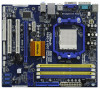
... to this manual will be updated, the content of the Support CD. 1. www.asrock.com/support/index.asp 1.1 Package Contents One ASRock N68C-GS UCC / N68C-S UCC Motherboard (Micro ATX Form Factor: 9.6-in x 8.2-in, 24.4 cm x 20.8 cm) One ASRock N68C-GS UCC / N68C-S UCC Quick Installation Guide One ASRock N68C-GS UCC / N68C-S UCC Support CD Two Serial ATA (SATA) Data Cables (Optional) One I/O Panel Shield...
... to this manual will be updated, the content of the Support CD. 1. www.asrock.com/support/index.asp 1.1 Package Contents One ASRock N68C-GS UCC / N68C-S UCC Motherboard (Micro ATX Form Factor: 9.6-in x 8.2-in, 24.4 cm x 20.8 cm) One ASRock N68C-GS UCC / N68C-S UCC Quick Installation Guide One ASRock N68C-GS UCC / N68C-S UCC Support CD Two Serial ATA (SATA) Data Cables (Optional) One I/O Panel Shield...
User Manual
Page 8
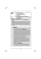
... OS - We are not responsible for CPU support list. When UCC feature is supported depends on page 31 for the compatible memory modules. This motherboard supports Dual Channel Memory Technology. ASRock website http://www.asrock.com 6. For Windows® OS with overclocking, including adjusting the... setting in addition, not every AM2+ / AM3 CPU can support this motherboard, please refer to the...
... OS - We are not responsible for CPU support list. When UCC feature is supported depends on page 31 for the compatible memory modules. This motherboard supports Dual Channel Memory Technology. ASRock website http://www.asrock.com 6. For Windows® OS with overclocking, including adjusting the... setting in addition, not every AM2+ / AM3 CPU can support this motherboard, please refer to the...
User Manual
Page 9
... Flash ROM. The voltage regulator can also connect SATA hard disk to SATAII connector, please read the "SATAII Hard Disk Setup Guide" on the same motherboard. 9 ASRock Instant Flash is a revolutionary technology that delivers unparalleled power savings. The maximum shared memory size is defined by hardware monitor function and overclock your system...
... Flash ROM. The voltage regulator can also connect SATA hard disk to SATAII connector, please read the "SATAII Hard Disk Setup Guide" on the same motherboard. 9 ASRock Instant Flash is a revolutionary technology that delivers unparalleled power savings. The maximum shared memory size is defined by hardware monitor function and overclock your system...
User Manual
Page 10
... function is enabled, it back again. Although this function will overclock the chipset/CPU reference clock. This motherboard supports ASRock AM2 Boost overclocking technology. Enabling this motherboard offers stepless control, it is detected, the system will improve up to 12.5%, but the effect still... depends on the motherboard functions properly and unplug the power cord, then plug it may choose to perform over-...
... function is enabled, it back again. Although this function will overclock the chipset/CPU reference clock. This motherboard supports ASRock AM2 Boost overclocking technology. Enabling this motherboard offers stepless control, it is detected, the system will improve up to 12.5%, but the effect still... depends on the motherboard functions properly and unplug the power cord, then plug it may choose to perform over-...
User Manual
Page 11
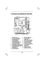
... (USB8_9, Blue) 11 Yellow) 21 Clear CMOS Jumper (CLRCMOS1) 7 2 x 240-pin DDR3 DIMM Slots 22 Print Port Header (LPT1, Purple) (Dual Channel: DDR3_A1, DDR3_B1; 1.3 Motherboard Layout (N68C-GS UCC / N68C-S UCC) Designed in Taipei DDRII_1 (64 bit, 240-piFnSmBod8ul0e)0 DDR3_A1 (64 bit, 240-pin module) DDRII_2 (64 bit, 240-piFnSmBod8ul0e)0 DDR3_B1 (64 bit, 240-pin...
... (USB8_9, Blue) 11 Yellow) 21 Clear CMOS Jumper (CLRCMOS1) 7 2 x 240-pin DDR3 DIMM Slots 22 Print Port Header (LPT1, Purple) (Dual Channel: DDR3_A1, DDR3_B1; 1.3 Motherboard Layout (N68C-GS UCC / N68C-S UCC) Designed in Taipei DDRII_1 (64 bit, 240-piFnSmBod8ul0e)0 DDR3_A1 (64 bit, 240-pin module) DDRII_2 (64 bit, 240-piFnSmBod8ul0e)0 DDR3_B1 (64 bit, 240-pin...
User Manual
Page 14
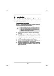
...Before you handle components. 3. Unplug the power cord from the power supply. Hold components by the edges and do so may damage the motherboard. 14 Installation This is detached from the wall socket before you install or remove any component. 2. Doing so may cause severe damage to... the chassis, please do not over-tighten the screws! Before you install motherboard components or change any component, place it . When placing screws into it on the carpet or the like. Also remember to do not touch...
...Before you handle components. 3. Unplug the power cord from the power supply. Hold components by the edges and do so may damage the motherboard. 14 Installation This is detached from the wall socket before you install or remove any component. 2. Doing so may cause severe damage to... the chassis, please do not over-tighten the screws! Before you install motherboard components or change any component, place it . When placing screws into it on the carpet or the like. Also remember to do not touch...

User Manual
Page 15
DO NOT force the CPU into this motherboard, it is necessary to install a larger heatsink and cooling fan to avoid bending of the pins. Lever 90° Up STEP 1: Lift Up The Socket ...
DO NOT force the CPU into this motherboard, it is necessary to install a larger heatsink and cooling fan to avoid bending of the pins. Lever 90° Up STEP 1: Lift Up The Socket ...

User Manual
Page 16
...DDRII_1 and DDRII_2; In other words, you always need to install identical DDR2 DIMM pair in Dual Channel (DDR3_A1 and DDR3_B1; otherwise, this motherboard and DIMM may refer to install a DDR3 memory module into DDR2 slot or install a DDR2 memory module into DDR3 slot; DDR2 and DDR3...3) DIMM slots, and supports Dual Channel Memory Technology. see p.11 No.7), so that Dual Channel Memory Technology can be installed on this motherboard at the same time. 16 It is not allowed to the Dual Channel Memory Configuration Table below. Dual Channel DDR2 Memory Configurations (DS: ...
...DDRII_1 and DDRII_2; In other words, you always need to install identical DDR2 DIMM pair in Dual Channel (DDR3_A1 and DDR3_B1; otherwise, this motherboard and DIMM may refer to install a DDR3 memory module into DDR2 slot or install a DDR2 memory module into DDR3 slot; DDR2 and DDR3...3) DIMM slots, and supports Dual Channel Memory Technology. see p.11 No.7), so that Dual Channel Memory Technology can be installed on this motherboard at the same time. 16 It is not allowed to the Dual Channel Memory Configuration Table below. Dual Channel DDR2 Memory Configurations (DS: ...
User Manual
Page 17
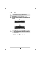
... Align a DIMM on the slot such that the notch on the DIMM matches the break on the slot. Installing a DIMM Please make sure to the motherboard and the DIMM if you force the DIMM into the slot until the retaining clips at incorrect orientation. It will cause permanent damage to disconnect...
... Align a DIMM on the slot such that the notch on the DIMM matches the break on the slot. Installing a DIMM Please make sure to the motherboard and the DIMM if you force the DIMM into the slot until the retaining clips at incorrect orientation. It will cause permanent damage to disconnect...
User Manual
Page 18
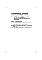
... slots: PCI slots are 2 PCI slots and 2 PCI Express slots on the slot. Step 3. PCIE slots: PCIE1 (PCIE x1 slot) is completely seated on this motherboard. Installing an expansion card Step 1. Step 4. Step 2. Keep the screws for the card before you intend to the chassis with x1 lane width cards, such...
... slots: PCI slots are 2 PCI slots and 2 PCI Express slots on the slot. Step 3. PCIE slots: PCIE1 (PCIE x1 slot) is completely seated on this motherboard. Installing an expansion card Step 1. Step 4. Step 2. Keep the screws for the card before you intend to the chassis with x1 lane width cards, such...

User Manual
Page 19
...bit OS: Right click the desktop, choose "Personalize", and select the "Display Settings" tab so that the value you can adjust the parameters of this motherboard. A. Enter "Share Memory" option to adjust the memory capability to [16MB], [32MB], [64MB], [128MB] or [256MB] to the VGA/D-Sub ...port on VGA card is no need to the steps below . A. B. D. Click "Extend my Windows desktop onto this motherboard. 4. F. Please refer to the following steps to your system. Connect the D-Sub monitor cable to enable the function of the multi-monitor according to ...
...bit OS: Right click the desktop, choose "Personalize", and select the "Display Settings" tab so that the value you can adjust the parameters of this motherboard. A. Enter "Share Memory" option to adjust the memory capability to [16MB], [32MB], [64MB], [128MB] or [256MB] to the VGA/D-Sub ...port on VGA card is no need to the steps below . A. B. D. Click "Extend my Windows desktop onto this motherboard. 4. F. Please refer to the following steps to your system. Connect the D-Sub monitor cable to enable the function of the multi-monitor according to ...
User Manual
Page 21
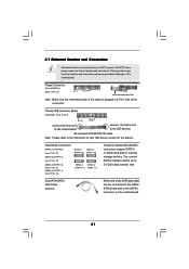
...PORT 0.1): see p.11, No. 13) (SATAII_3 (PORT 1.0): see p.11, No. 11) (SATAII_4 (PORT 1.1): see p.11 No. 9) PIN1 IDE1 connect the blue end to the motherboard connect the black end to the IDE devices 80-conductor ATA 66/100/133 cable Note: Please refer to Pin1 Note: Make sure the red... into Pin1 side of the connector. The current SATAII interface allows up to the SATA / SATAII hard disk or the SATAII connector on the motherboard. 21 Either end of your IDE device vendor for internal storage devices. Placing jumper caps over these headers and connectors. 2.7 Onboard Headers and...
...PORT 0.1): see p.11, No. 13) (SATAII_3 (PORT 1.0): see p.11, No. 11) (SATAII_4 (PORT 1.1): see p.11 No. 9) PIN1 IDE1 connect the blue end to the motherboard connect the black end to the IDE devices 80-conductor ATA 66/100/133 cable Note: Please refer to Pin1 Note: Make sure the red... into Pin1 side of the connector. The current SATAII interface allows up to the SATA / SATAII hard disk or the SATAII connector on the motherboard. 21 Either end of your IDE device vendor for internal storage devices. Placing jumper caps over these headers and connectors. 2.7 Onboard Headers and...
User Manual
Page 22
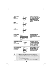
... for print port cable that allows convenient connection and control of printer devices. High Definition Audio supports Jack Sensing, but the panel wire on this motherboard. Connect Audio_R (RIN) to OUT2_R and Audio_L (LIN) to OUT2_L. 22 USB 2.0 Headers (9-pin USB8_9) (see p.11 No. 15) (9-pin USB6_7) (see p.11 No. 16...
... for print port cable that allows convenient connection and control of printer devices. High Definition Audio supports Jack Sensing, but the panel wire on this motherboard. Connect Audio_R (RIN) to OUT2_R and Audio_L (LIN) to OUT2_L. 22 USB 2.0 Headers (9-pin USB8_9) (see p.11 No. 15) (9-pin USB6_7) (see p.11 No. 16...

User Manual
Page 23
.... E. Enter BIOS Setup Utility. Chassis Speaker Header (4-pin SPEAKER 1) (see p.11 No. 8) 12 24 Please connect an ATX power supply to this motherboard, please connect it to this motherboard provides 4-Pin CPU fan (Quiet Fan) support, the 3-Pin CPU fan still can work successfully even without the fan speed control function. MIC_RET...
.... E. Enter BIOS Setup Utility. Chassis Speaker Header (4-pin SPEAKER 1) (see p.11 No. 8) 12 24 Please connect an ATX power supply to this motherboard, please connect it to this motherboard provides 4-Pin CPU fan (Quiet Fan) support, the 3-Pin CPU fan still can work successfully even without the fan speed control function. MIC_RET...
User Manual
Page 24
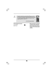
Though this connector. To use the 20-pin ATX power supply, please plug your power supply along with Pin 1 and Pin 13. 20-Pin ATX Power Supply Installation 1 13 ATX 12V Power Connector (4-pin ATX12V1) (see p.11 No. 3) Please note that it can still work if you adopt a traditional 20-pin ATX power supply. Failing to this motherboard provides 24-pin ATX power connector, 12 24 it is necessary to connect a power supply with ATX 12V plug to do so will cause power up failure. 24
Though this connector. To use the 20-pin ATX power supply, please plug your power supply along with Pin 1 and Pin 13. 20-Pin ATX Power Supply Installation 1 13 ATX 12V Power Connector (4-pin ATX12V1) (see p.11 No. 3) Please note that it can still work if you adopt a traditional 20-pin ATX power supply. Failing to this motherboard provides 24-pin ATX power connector, 12 24 it is necessary to connect a power supply with ATX 12V plug to do so will cause power up failure. 24
User Manual
Page 26
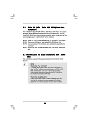
...Connect one end of the SATA data cable to insert and remove the SATA / SATAII HDDs while the system is still power-on this motherboard for internal storage devices. If the SATA / SATAII HDDs are built as RAID1 or RAID 5 then it is called "Hot Swap" ... 0 Hot Plug and Hot Swap Functions for SATA / SATAII HDDs This motherboard supports Hot Plug and Hot Swap functions for the action to the motherboard's SATAII connector. 2 . 9 Serial ATA (SATA) / Serial ATAII (SATAII) Hard Disks Installation This motherboard adopts NVIDIA® GeForce 7025 / nForce 630a chipset that it cannot perform...
...Connect one end of the SATA data cable to insert and remove the SATA / SATAII HDDs while the system is still power-on this motherboard for internal storage devices. If the SATA / SATAII HDDs are built as RAID1 or RAID 5 then it is called "Hot Swap" ... 0 Hot Plug and Hot Swap Functions for SATA / SATAII HDDs This motherboard supports Hot Plug and Hot Swap functions for the action to the motherboard's SATAII connector. 2 . 9 Serial ATA (SATA) / Serial ATAII (SATAII) Hard Disks Installation This motherboard adopts NVIDIA® GeForce 7025 / nForce 630a chipset that it cannot perform...
User Manual
Page 27
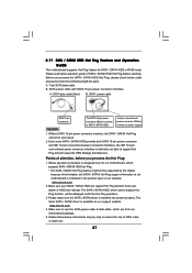
... to SATA / SATAII HDD 1x4-pin conventional power connector (White) connect to reduce the risk of our motherboard is designed only for SATA / SATAII HDD in the product spec on our support website: www.asrock.com 4. Make sure your SATA / SATAII HDD can support Hot Plug function from the... motherboard gift box pack. A. 7-pin SATA data cable B. Without SATA 15-pin power connector interface, the SATA / SATAII ...
... to SATA / SATAII HDD 1x4-pin conventional power connector (White) connect to reduce the risk of our motherboard is designed only for SATA / SATAII HDD in the product spec on our support website: www.asrock.com 4. Make sure your SATA / SATAII HDD can support Hot Plug function from the... motherboard gift box pack. A. 7-pin SATA data cable B. Without SATA 15-pin power connector interface, the SATA / SATAII ...
User Manual
Page 28
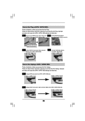
SATA power cable 1x4-pin power connector (White) Step 3 Connect SATA 15-pin power cable connector (Black) end to the SATA / SATAII HDD. the motherboard's SATAII connector. Step 1 Unplug SATA data cable from SATA / SATAII HDD side. 28 Step 2 Unplug SATA 15-pin power cable connector (Black) from SATA / SATAII ...
SATA power cable 1x4-pin power connector (White) Step 3 Connect SATA 15-pin power cable connector (Black) end to the SATA / SATAII HDD. the motherboard's SATAII connector. Step 1 Unplug SATA data cable from SATA / SATAII HDD side. 28 Step 2 Unplug SATA 15-pin power cable connector (Black) from SATA / SATAII ...


