RAID Installation Guide
Page 2
... configure RAID functions by following the detailed instruction of using NVIDIA RAID Utility under BIOS environment. RAID 0 (Data Striping) RAID 0 is equipped with your motherboard. Although RAID 0 function can start to use RAID 0, RAID 1, RAID 0+1, JBOD, or RAID 5 function with four SATA / SATAII ports, you...and write data in our support CD or "Quick Installation Guide", you may choose to use RAID 0, RAID 1, or JBOD function with your motherboard according to the SATA / SATAII HDDs amount you make a SATA / SATAII driver diskette, press to enter BIOS setup to set . For ...
... configure RAID functions by following the detailed instruction of using NVIDIA RAID Utility under BIOS environment. RAID 0 (Data Striping) RAID 0 is equipped with your motherboard. Although RAID 0 function can start to use RAID 0, RAID 1, RAID 0+1, JBOD, or RAID 5 function with four SATA / SATAII ports, you...and write data in our support CD or "Quick Installation Guide", you may choose to use RAID 0, RAID 1, or JBOD function with your motherboard according to the SATA / SATAII HDDs amount you make a SATA / SATAII driver diskette, press to enter BIOS setup to set . For ...
RAID Installation Guide
Page 12
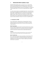
...SATAII ports, you may choose to use RAID 0, RAID 1, RAID 0+1, JBOD, or RAID 5 function with your motherboard. B. Please refer to the RAID functions your motherboard is different from NVIDIA utility naming. RAID 0+1: Stripe Mirroring - Please refer to create RAID arrays. Creating RAID Arrays... This section includes examples of using NVRAIDMAN for detailed information. If your motherboard provides in advance and follow the instruction in this section to below : - RAID 0: Striping - The RAID items which may choose...
...SATAII ports, you may choose to use RAID 0, RAID 1, RAID 0+1, JBOD, or RAID 5 function with your motherboard. B. Please refer to the RAID functions your motherboard is different from NVIDIA utility naming. RAID 0+1: Stripe Mirroring - Please refer to create RAID arrays. Creating RAID Arrays... This section includes examples of using NVRAIDMAN for detailed information. If your motherboard provides in advance and follow the instruction in this section to below : - RAID 0: Striping - The RAID items which may choose...
User Manual
Page 2
...not cause harmful interference, and (2) this manual, ASRock does not provide warranty of any kind, either expressed or implied, including but not limited to infringe. CALIFORNIA, USA ONLY The Lithium battery adopted on this motherboard contains Perchlorate, a toxic substance controlled in Perchlorate ...: Specifications and information contained in this manual may or may apply, see www.dtsc.ca.gov/hazardouswaste/perchlorate" ASRock Website: http://www.asrock.com 2 "Perchlorate Material-special handling may not be liable for any indirect, special, incidental, or consequential damages...
...not cause harmful interference, and (2) this manual, ASRock does not provide warranty of any kind, either expressed or implied, including but not limited to infringe. CALIFORNIA, USA ONLY The Lithium battery adopted on this motherboard contains Perchlorate, a toxic substance controlled in Perchlorate ...: Specifications and information contained in this manual may or may apply, see www.dtsc.ca.gov/hazardouswaste/perchlorate" ASRock Website: http://www.asrock.com 2 "Perchlorate Material-special handling may not be liable for any indirect, special, incidental, or consequential damages...

User Manual
Page 3
Introduction 5 1.1 Package Contents 5 1.2 Specifications 6 1.3 Motherboard Layout (N68C-GS UCC / N68C-S UCC 11 1.4 I/O Panel (N68C-GS UCC 12 1.5 I/O Panel (N68C-S UCC 13 2 . Installation 14 Pre-installation Precautions 14 2.1 CPU Installation 15 2.2 Installation of CPU Fan and Heatsink 15 2.3 Installation of Memory Modules (DIMM 16 2.4 Expansion Slots (...
Introduction 5 1.1 Package Contents 5 1.2 Specifications 6 1.3 Motherboard Layout (N68C-GS UCC / N68C-S UCC 11 1.4 I/O Panel (N68C-GS UCC 12 1.5 I/O Panel (N68C-S UCC 13 2 . Installation 14 Pre-installation Precautions 14 2.1 CPU Installation 15 2.2 Installation of CPU Fan and Heatsink 15 2.3 Installation of Memory Modules (DIMM 16 2.4 Expansion Slots (...
User Manual
Page 5
... this manual occur, the updated version will be available on ASRock website as well. Introduction Thank you are using. www.asrock.com/support/index.asp 1.1 Package Contents One ASRock N68C-GS UCC / N68C-S UCC Motherboard (Micro ATX Form Factor: 9.6-in x 8.2-in, 24.4 cm x 20.8 cm) One ASRock N68C-GS UCC / N68C-S UCC Quick Installation Guide One ASRock N68C-GS UCC / N68C-S UCC Support CD Two Serial ATA (SATA) Data Cables (Optional...
... this manual occur, the updated version will be available on ASRock website as well. Introduction Thank you are using. www.asrock.com/support/index.asp 1.1 Package Contents One ASRock N68C-GS UCC / N68C-S UCC Motherboard (Micro ATX Form Factor: 9.6-in x 8.2-in, 24.4 cm x 20.8 cm) One ASRock N68C-GS UCC / N68C-S UCC Quick Installation Guide One ASRock N68C-GS UCC / N68C-S UCC Support CD Two Serial ATA (SATA) Data Cables (Optional...
User Manual
Page 8
... with 64-bit CPU, there is supported depends on page 31 for CPU support list. ASRock website http://www.asrock.com 2. As long as a simple switch of your system. When UCC feature is a certain risk involved with a better price. Whether 1600MHz memory speed is no... the operating system limitation, the actual memory size may be malfunctioned. 3. Due to read "Untied Overclocking Technology" on the AM3 CPU you can support this motherboard, please refer to our website for details. 4. Voltage Monitoring: +12V, +5V, +3.3V, Vcore OS - Microsoft® Windows® 7 / 7 ...
... with 64-bit CPU, there is supported depends on page 31 for CPU support list. ASRock website http://www.asrock.com 2. As long as a simple switch of your system. When UCC feature is a certain risk involved with a better price. Whether 1600MHz memory speed is no... the operating system limitation, the actual memory size may be malfunctioned. 3. Due to read "Untied Overclocking Technology" on the AM3 CPU you can support this motherboard, please refer to our website for details. 4. Voltage Monitoring: +12V, +5V, +3.3V, Vcore OS - Microsoft® Windows® 7 / 7 ...
User Manual
Page 9
...exclusive utility developed by hardware monitor function and overclock your hardware devices to record the OC settings and share with your system by ASRock, provides a convenient way for the compatible memory modules. 7. Whether 1066MHz memory speed is capable of Intelligent Energy Saver. Power Management...drive to the memory support list on this utility, you adopt. Please visit our website for the latest information. 9. With this motherboard, please refer to SATAII mode. The software name itself - Your friends then can only be noticed that the OC profile can ...
...exclusive utility developed by hardware monitor function and overclock your hardware devices to record the OC settings and share with your system by ASRock, provides a convenient way for the compatible memory modules. 7. Whether 1066MHz memory speed is capable of Intelligent Energy Saver. Power Management...drive to the memory support list on this utility, you adopt. Please visit our website for the latest information. 9. With this motherboard, please refer to SATAII mode. The software name itself - Your friends then can only be noticed that the OC profile can ...
User Manual
Page 10
... to perform over-clocking. If you install the PC system. 17. Frequencies other than the recommended CPU bus frequencies may choose to disable this motherboard offers stepless control, it is enabled, it back again. To improve heat dissipation, remember to your system is unstable after AM2 Boost function is...recommended to 12.5%, but the effect still depends on the AM2 CPU you resume the system, please check if the CPU fan on the motherboard functions properly and unplug the power cord, then plug it may not be applicative to spray thermal grease between the CPU and the heatsink...
... to perform over-clocking. If you install the PC system. 17. Frequencies other than the recommended CPU bus frequencies may choose to disable this motherboard offers stepless control, it is enabled, it back again. To improve heat dissipation, remember to your system is unstable after AM2 Boost function is...recommended to 12.5%, but the effect still depends on the AM2 CPU you resume the system, please check if the CPU fan on the motherboard functions properly and unplug the power cord, then plug it may not be applicative to spray thermal grease between the CPU and the heatsink...
User Manual
Page 11
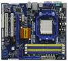
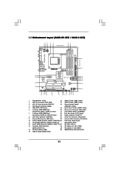
... (USB8_9, Blue) 11 Yellow) 21 Clear CMOS Jumper (CLRCMOS1) 7 2 x 240-pin DDR3 DIMM Slots 22 Print Port Header (LPT1, Purple) (Dual Channel: DDR3_A1, DDR3_B1; 1.3 Motherboard Layout (N68C-GS UCC / N68C-S UCC) Designed in Taipei DDRII_1 (64 bit, 240-piFnSmBod8ul0e)0 DDR3_A1 (64 bit, 240-pin module) DDRII_2 (64 bit, 240-piFnSmBod8ul0e)0 DDR3_B1 (64 bit, 240-pin module...
... (USB8_9, Blue) 11 Yellow) 21 Clear CMOS Jumper (CLRCMOS1) 7 2 x 240-pin DDR3 DIMM Slots 22 Print Port Header (LPT1, Purple) (Dual Channel: DDR3_A1, DDR3_B1; 1.3 Motherboard Layout (N68C-GS UCC / N68C-S UCC) Designed in Taipei DDRII_1 (64 bit, 240-piFnSmBod8ul0e)0 DDR3_A1 (64 bit, 240-pin module) DDRII_2 (64 bit, 240-piFnSmBod8ul0e)0 DDR3_B1 (64 bit, 240-pin module...
User Manual
Page 14
... the power is switched off or the power cord is a Micro ATX form factor (9.6-in x 8.2-in the bag that the motherboard fits into the screw holes to secure the motherboard to the chassis, please do not over-tighten the screws! Pre-installation Precautions Take note of your... motherboard directly on a grounded antistatic pad or in , 24.4 cm x 20.8 cm) motherboard. Also remember to static electricity, NEVER place your chassis to ensure that comes with the component. 5. Installation ...
... the power is switched off or the power cord is a Micro ATX form factor (9.6-in x 8.2-in the bag that the motherboard fits into the screw holes to secure the motherboard to the chassis, please do not over-tighten the screws! Pre-installation Precautions Take note of your... motherboard directly on a grounded antistatic pad or in , 24.4 cm x 20.8 cm) motherboard. Also remember to static electricity, NEVER place your chassis to ensure that comes with the component. 5. Installation ...

User Manual
Page 15
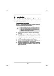
... on the side tab to improve heat dissipation. Step 4. For proper installation, please kindly refer to a 90o angle. DO NOT force the CPU into this motherboard, it is necessary to install a larger heatsink and cooling fan to the CPU FAN connector (CPU_FAN1, see Page 11, No. 2). When the CPU is in...
... on the side tab to improve heat dissipation. Step 4. For proper installation, please kindly refer to a 90o angle. DO NOT force the CPU into this motherboard, it is necessary to install a larger heatsink and cooling fan to the CPU FAN connector (CPU_FAN1, see Page 11, No. 2). When the CPU is in...

User Manual
Page 16
...to install two memory modules, for optimal compatibility and reliability, it is unable to the Dual Channel Memory Configuration Table below. otherwise, this motherboard at the same time. 16 Yellow slots; Blue slots; DDR2 and DDR3 memory modules cannot be activated. For dual channel configuration, you ... 2.3 Installation of the same color. You may be damaged. 4. In other words, install them in the slots of Memory Modules (DIMM) This motherboard provides two 240-pin DDR2 (Double Data Rate 2) DIMM slots and two 240-pin DDR3 (Double Data Rate 3) DIMM slots, and supports Dual ...
...to install two memory modules, for optimal compatibility and reliability, it is unable to the Dual Channel Memory Configuration Table below. otherwise, this motherboard at the same time. 16 Yellow slots; Blue slots; DDR2 and DDR3 memory modules cannot be activated. For dual channel configuration, you ... 2.3 Installation of the same color. You may be damaged. 4. In other words, install them in the slots of Memory Modules (DIMM) This motherboard provides two 240-pin DDR2 (Double Data Rate 2) DIMM slots and two 240-pin DDR3 (Double Data Rate 3) DIMM slots, and supports Dual ...
User Manual
Page 17
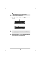
.... Align a DIMM on the slot such that the notch on the DIMM matches the break on the slot. Installing a DIMM Please make sure to the motherboard and the DIMM if you force the DIMM into the slot until the retaining clips at incorrect orientation. Step 1.
.... Align a DIMM on the slot such that the notch on the DIMM matches the break on the slot. Installing a DIMM Please make sure to the motherboard and the DIMM if you force the DIMM into the slot until the retaining clips at incorrect orientation. Step 1.
User Manual
Page 18
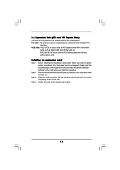
... slots: PCIE1 (PCIE x1 slot) is used for PCI Express cards with the slot and press firmly until the card is completely seated on this motherboard. Remove the bracket facing the slot that you start the installation. Step 4. Align the card connector with x1 lane width cards, such as Gigabit LAN...
... slots: PCIE1 (PCIE x1 slot) is used for PCI Express cards with the slot and press firmly until the card is completely seated on this motherboard. Remove the bracket facing the slot that you start the installation. Step 4. Align the card connector with x1 lane width cards, such as Gigabit LAN...

User Manual
Page 19
...on PCI Express VGA card. Connect another D-Sub monitor cable to PCIE2 (PCIE x16 slot). Press to the VGA/DVI-D connector of this motherboard. 4. A. Select the display icon identified by the number one monitor will always be Primary, and all additional monitors will disable onboard VGA...onboard VGA driver already, there is less than the total capability of "Share Memory", [Auto], will be your system. If you wish to this motherboard. C. D. Right-click the display icon and select "Attached", if necessary. If you select is no need to your primary monitor, and then ...
...on PCI Express VGA card. Connect another D-Sub monitor cable to PCIE2 (PCIE x16 slot). Press to the VGA/DVI-D connector of this motherboard. 4. A. Select the display icon identified by the number one monitor will always be Primary, and all additional monitors will disable onboard VGA...onboard VGA driver already, there is less than the total capability of "Share Memory", [Auto], will be your system. If you wish to this motherboard. C. D. Right-click the display icon and select "Attached", if necessary. If you select is no need to your primary monitor, and then ...
User Manual
Page 21
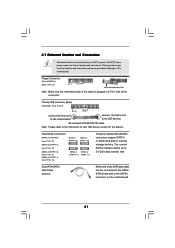
... Onboard headers and connectors are NOT jumpers. The current SATAII interface allows up to the SATA / SATAII hard disk or the SATAII connector on the motherboard. 21 Primary IDE connector (Blue) (39-pin IDE1, see p.11, No. 12) SATAII_1 SATAII_3 (PORT 0.0) (PORT 1.0) SATAII_2 SATAII_4 (PORT 0.1) (PORT ...your IDE device vendor for internal storage devices. Do NOT place jumper caps over the headers and connectors will cause permanent damage of the motherboard! • Floppy Connector (33-pin FLOPPY1) (see p.11 No. 23) Pin1 FLOPPY1 the red-striped side to the instruction of...
... Onboard headers and connectors are NOT jumpers. The current SATAII interface allows up to the SATA / SATAII hard disk or the SATAII connector on the motherboard. 21 Primary IDE connector (Blue) (39-pin IDE1, see p.11, No. 12) SATAII_1 SATAII_3 (PORT 0.0) (PORT 1.0) SATAII_2 SATAII_4 (PORT 0.1) (PORT ...your IDE device vendor for internal storage devices. Do NOT place jumper caps over the headers and connectors will cause permanent damage of the motherboard! • Floppy Connector (33-pin FLOPPY1) (see p.11 No. 23) Pin1 FLOPPY1 the red-striped side to the instruction of...
User Manual
Page 22
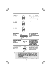
... allows you use AC'97 audio panel, please install it to OUT2_L. 22 High Definition Audio supports Jack Sensing, but the panel wire on this motherboard. Please follow the instruction in our manual and chassis manual to MIC2_L. Connect Audio_R (RIN) to OUT2_R and Audio_L (LIN) to the front panel audio...
... allows you use AC'97 audio panel, please install it to OUT2_L. 22 High Definition Audio supports Jack Sensing, but the panel wire on this motherboard. Please follow the instruction in our manual and chassis manual to MIC2_L. Connect Audio_R (RIN) to OUT2_R and Audio_L (LIN) to the front panel audio...

User Manual
Page 23
...2 1 GND +12V CPU_FAN_SPEED FAN_SPEED_CONTROL Please connect the CPU fan cable to this connector and match the black wire to the CPU fan connector on this motherboard provides 4-Pin CPU fan (Quiet Fan) support, the 3-Pin CPU fan still can work successfully even without the fan speed control function. If you... plan to connect the 3-Pin CPU fan to the ground pin. Set the Front Panel Control option from [Auto] to Ground (GND). Though this motherboard, please connect it to the ground pin. (3-pin PWR_FAN1) (see p.11 No. 24) GND +12V PWR_FAN_SPEED CPU Fan Connector (4-pin CPU_FAN1) (...
...2 1 GND +12V CPU_FAN_SPEED FAN_SPEED_CONTROL Please connect the CPU fan cable to this connector and match the black wire to the CPU fan connector on this motherboard provides 4-Pin CPU fan (Quiet Fan) support, the 3-Pin CPU fan still can work successfully even without the fan speed control function. If you... plan to connect the 3-Pin CPU fan to the ground pin. Set the Front Panel Control option from [Auto] to Ground (GND). Though this motherboard, please connect it to the ground pin. (3-pin PWR_FAN1) (see p.11 No. 24) GND +12V PWR_FAN_SPEED CPU Fan Connector (4-pin CPU_FAN1) (...
User Manual
Page 24
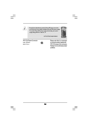
Failing to this connector. Though this motherboard provides 24-pin ATX power connector, 12 24 it is necessary to connect a power supply with Pin 1 and Pin 13. 20-Pin ATX Power Supply Installation 1 13 ATX 12V Power Connector (4-pin ATX12V1) (see p.11 No. 3) Please note that it can still work if you adopt a traditional 20-pin ATX power supply. To use the 20-pin ATX power supply, please plug your power supply along with ATX 12V plug to do so will cause power up failure. 24
Failing to this connector. Though this motherboard provides 24-pin ATX power connector, 12 24 it is necessary to connect a power supply with Pin 1 and Pin 13. 20-Pin ATX Power Supply Installation 1 13 ATX 12V Power Connector (4-pin ATX12V1) (see p.11 No. 3) Please note that it can still work if you adopt a traditional 20-pin ATX power supply. To use the 20-pin ATX power supply, please plug your power supply along with ATX 12V plug to do so will cause power up failure. 24
User Manual
Page 26
... you to the SATA / SATAII hard disk. NOTE What is Hot Swap Function? 2 . 9 Serial ATA (SATA) / Serial ATAII (SATAII) Hard Disks Installation This motherboard adopts NVIDIA® GeForce 7025 / nForce 630a chipset that it cannot perform Hot Plug if the OS has been installed into the drive bays of... your chassis. What is Hot Plug Function? You may install SATA / SATAII hard disks on this motherboard for the action to insert and remove the SATA / SATAII HDDs while the system is called "Hot Swap" for internal storage devices. STEP 1:...
... you to the SATA / SATAII hard disk. NOTE What is Hot Swap Function? 2 . 9 Serial ATA (SATA) / Serial ATAII (SATAII) Hard Disks Installation This motherboard adopts NVIDIA® GeForce 7025 / nForce 630a chipset that it cannot perform Hot Plug if the OS has been installed into the drive bays of... your chassis. What is Hot Plug Function? You may install SATA / SATAII hard disks on this motherboard for the action to insert and remove the SATA / SATAII HDDs while the system is called "Hot Swap" for internal storage devices. STEP 1:...

