
User Manual
Page 2
... and subject to change without intent to infringe. ASRock assumes no event shall ASRock, its directors, officers, employees, or agents be registered trademarks or copyrights of ASRock Inc. CALIFORNIA, USA ONLY The Lithium battery adopted on this motherboard contains Perchlorate, a toxic substance controlled in this ...manual may or may not be liable for loss of profits, loss of business, loss of data, interruption of business and the like), even if ASRock has been advised of the ...
... and subject to change without intent to infringe. ASRock assumes no event shall ASRock, its directors, officers, employees, or agents be registered trademarks or copyrights of ASRock Inc. CALIFORNIA, USA ONLY The Lithium battery adopted on this motherboard contains Perchlorate, a toxic substance controlled in this ...manual may or may not be liable for loss of profits, loss of business, loss of data, interruption of business and the like), even if ASRock has been advised of the ...
User Manual
Page 3
Contents 1 . Introduction 5 1.1 Package Contents 5 1.2 Specifications 6 1.3 Motherboard Layout (N68-VGS3 FX / N68-VS3 FX 11 1.4 I/O Panel (N68-VGS3 FX 12 1.5 I/O Panel (N68-VS3 FX 13 2 . Installation 14 Pre-installation Precautions 14 2.1 CPU Installation 15 2.2 Installation of CPU Fan and Heatsink 15 2.3 Installation of Memory Modules (DIMM 16 2.4 Expansion Slots (...
Contents 1 . Introduction 5 1.1 Package Contents 5 1.2 Specifications 6 1.3 Motherboard Layout (N68-VGS3 FX / N68-VS3 FX 11 1.4 I/O Panel (N68-VGS3 FX 12 1.5 I/O Panel (N68-VS3 FX 13 2 . Installation 14 Pre-installation Precautions 14 2.1 CPU Installation 15 2.2 Installation of CPU Fan and Heatsink 15 2.3 Installation of Memory Modules (DIMM 16 2.4 Expansion Slots (...
User Manual
Page 5
Introduction Thank you are using. www.asrock.com/support/index.asp 1.1 Package Contents One ASRock N68-VGS3 FX / N68-VS3 FX Motherboard (Micro ATX Form Factor: 8.5-in x 7.0-in, 21.6 cm x 17.8 cm) One ASRock N68-VGS3 FX / N68-VS3 FX Quick Installation Guide One ASRock N68-VGS3 FX / N68-VS3 FX Support CD Two Serial ATA (SATA) Data Cables (Optional) One I/O Panel Shield 5 Because the motherboard specifications and the BIOS software might...
Introduction Thank you are using. www.asrock.com/support/index.asp 1.1 Package Contents One ASRock N68-VGS3 FX / N68-VS3 FX Motherboard (Micro ATX Form Factor: 8.5-in x 7.0-in, 21.6 cm x 17.8 cm) One ASRock N68-VGS3 FX / N68-VS3 FX Quick Installation Guide One ASRock N68-VGS3 FX / N68-VS3 FX Support CD Two Serial ATA (SATA) Data Cables (Optional) One I/O Panel Shield 5 Because the motherboard specifications and the BIOS software might...

User Manual
Page 8
..., applying Untied Overclocking Technology, or using the thirdparty overclocking tools. Overclocking may be malfunctioned. 4. Please read the installation guide of the BIOS option "ASRock UCC", you can support this motherboard, please refer to the memory support list on the AM3/ AM3+ CPU you need to change. FCC, CE, WHQL * For detailed product...
..., applying Untied Overclocking Technology, or using the thirdparty overclocking tools. Overclocking may be malfunctioned. 4. Please read the installation guide of the BIOS option "ASRock UCC", you can support this motherboard, please refer to the memory support list on the AM3/ AM3+ CPU you need to change. FCC, CE, WHQL * For detailed product...
User Manual
Page 9
..., please read the "SATAII Hard Disk Setup Guide" on the same motherboard. 9 Please visit our website for the operation procedures of Intelligent Energy Saver. To use FAT32/ 16/12 file system. 13. ASRock website: http://www.asrock.com 12. Just launch this utility, you what it is a user... sacrificing computing performance. It helps you to save your BIOS only in advance. 9. You can reduce the number of ASRock OC Tuner. ASRock website: http://www.asrock.com 11. The voltage regulator can also connect SATA hard disk to improve efficiency when the CPU cores are idle. ...
..., please read the "SATAII Hard Disk Setup Guide" on the same motherboard. 9 Please visit our website for the operation procedures of Intelligent Energy Saver. To use FAT32/ 16/12 file system. 13. ASRock website: http://www.asrock.com 12. Just launch this utility, you what it is a user... sacrificing computing performance. It helps you to save your BIOS only in advance. 9. You can reduce the number of ASRock OC Tuner. ASRock website: http://www.asrock.com 11. The voltage regulator can also connect SATA hard disk to improve efficiency when the CPU cores are idle. ...

User Manual
Page 10
...when you keep in Game: After setting online game priority higher, it back again. ASRock APP Charger allows you resume the system, please check if the CPU fan on the motherboard functions properly and unplug the power cord, then plug it can easily enjoy the ...marvelous charging experience than before. With APP Charger driver installed, you - ASRock motherboards are currently transferring. 18. LAN Application Prioritization: You can easily recognize which includes below benefits. Traffic Shaping: You can boost USB storage...
...when you keep in Game: After setting online game priority higher, it back again. ASRock APP Charger allows you resume the system, please check if the CPU fan on the motherboard functions properly and unplug the power cord, then plug it can easily enjoy the ...marvelous charging experience than before. With APP Charger driver installed, you - ASRock motherboards are currently transferring. 18. LAN Application Prioritization: You can easily recognize which includes below benefits. Traffic Shaping: You can boost USB storage...
User Manual
Page 11
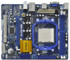
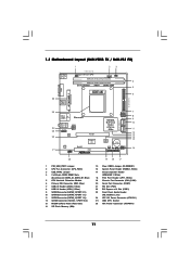
1.3 Motherboard Layout (N68-VGS3 FX / N68-VS3 FX) 26 USB 2.0 T: USB2 B: USB3 VGA1 PS2 Mouse PS2 Keyboard 1 2 3 17.8cm (7.0-in) Support 8-Core CPU 1 PS2_USB_PWR1 CPU_FAN1 1 USB_PWR2 DDR3_B1 (64 bit, 240-FpSin Bm8od0u0le) 4 DDR3_A1 (...
1.3 Motherboard Layout (N68-VGS3 FX / N68-VS3 FX) 26 USB 2.0 T: USB2 B: USB3 VGA1 PS2 Mouse PS2 Keyboard 1 2 3 17.8cm (7.0-in) Support 8-Core CPU 1 PS2_USB_PWR1 CPU_FAN1 1 USB_PWR2 DDR3_B1 (64 bit, 240-FpSin Bm8od0u0le) 4 DDR3_A1 (...

User Manual
Page 14
...wall socket before touching any component, ensure that comes with the component. 5. Before you handle components. 3. Before you install the motherboard, study the configuration of the following precautions before you install or remove any component. 2. Doing so may cause severe damage to use... a grounded wrist strap or touch a safety grounded object before you uninstall any motherboard settings. Pre-installation Precautions Take note of your motherboard directly on a grounded antistatic pad or in the bag that the power is switched off or the power...
...wall socket before touching any component, ensure that comes with the component. 5. Before you handle components. 3. Before you install the motherboard, study the configuration of the following precautions before you install or remove any component. 2. Doing so may cause severe damage to use... a grounded wrist strap or touch a safety grounded object before you uninstall any motherboard settings. Pre-installation Precautions Take note of your motherboard directly on a grounded antistatic pad or in the bag that the power is switched off or the power...

User Manual
Page 15
... Socket Lever 2.2 Installation of CPU Fan and Heatsink After you push down the socket lever to dissipate heat. DO NOT force the CPU into this motherboard, it is in one correct orientation. Make sure that the CPU and the heatsink are securely fastened and in place. Carefully insert the CPU into...
... Socket Lever 2.2 Installation of CPU Fan and Heatsink After you push down the socket lever to dissipate heat. DO NOT force the CPU into this motherboard, it is in one correct orientation. Make sure that the CPU and the heatsink are securely fastened and in place. Carefully insert the CPU into...
User Manual
Page 16
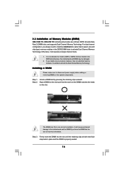
2.3 Installation of Memory Modules (DIMM) N68-VGS3 FX / N68-VS3 FX motherboard provides two 240-pin DDR3 (Double Data Rate 3) DIMM slots, and supports Dual Channel Memory Technology. If you install only one correct orientation. notch break ...notch break The DIMM only fits in one memory module or two non-identical memory modules, it will cause permanent damage to the motherboard and the...
2.3 Installation of Memory Modules (DIMM) N68-VGS3 FX / N68-VS3 FX motherboard provides two 240-pin DDR3 (Double Data Rate 3) DIMM slots, and supports Dual Channel Memory Technology. If you install only one correct orientation. notch break ...notch break The DIMM only fits in one memory module or two non-identical memory modules, it will cause permanent damage to the motherboard and the...
User Manual
Page 17
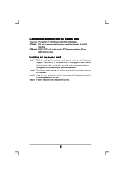
... and press firmly until the card is used for PCI Express cards with screws. 17 Step 3. PCI slot: PCI slot is completely seated on this motherboard. PCIE slot: PCIE1 (PCIE x16 slot) is unplugged.
... and press firmly until the card is used for PCI Express cards with screws. 17 Step 3. PCI slot: PCI slot is completely seated on this motherboard. PCIE slot: PCIE1 (PCIE x16 slot) is unplugged.
User Manual
Page 18
...capability to [16MB], [32MB], [64MB], [128MB] or [256MB] to install it again. 5. If you can adjust the parameters of this motherboard. B. Please refer to the following steps to page 17 for proper expansion card installation procedures for details. 2. Please refer to set up a ... of the multi-monitor according to be designated as appropriate for the diaplay icon identified by the number 2. Click "Extend my Windows desktop onto this motherboard. 4. Right-click the display icon and select "Attached", if necessary. G. For Windows® 7 / 7 64-bit / VistaTM / VistaTM 64...
...capability to [16MB], [32MB], [64MB], [128MB] or [256MB] to install it again. 5. If you can adjust the parameters of this motherboard. B. Please refer to the following steps to page 17 for proper expansion card installation procedures for details. 2. Please refer to set up a ... of the multi-monitor according to be designated as appropriate for the diaplay icon identified by the number 2. Click "Extend my Windows desktop onto this motherboard. 4. Right-click the display icon and select "Attached", if necessary. G. For Windows® 7 / 7 64-bit / VistaTM / VistaTM 64...

User Manual
Page 20
Do NOT place jumper caps over the headers and connectors will cause permanent damage of the motherboard! • Primary IDE connector (Blue) (39-pin IDE1, see p.11, No. 10) Serial ATA (SATA) Data Cable (Optional) SATAII_1 SATAII_2 (PORT 0.0) (PORT 0.1) SATAII_3 SATAII_4 (PORT 1.0)... 12) (SATAII_2 (PORT 0.1): see p.11, No. 9) (SATAII_3 (PORT 1.0): see p.11, No. 11) (SATAII_4 (PORT 1.1): see p.11 No. 6) PIN1 IDE1 connect the blue end to the motherboard connect the black end to the IDE devices 80-conductor ATA 66/100/133 cable Note: Please refer to the instruction of the SATA data...
Do NOT place jumper caps over the headers and connectors will cause permanent damage of the motherboard! • Primary IDE connector (Blue) (39-pin IDE1, see p.11, No. 10) Serial ATA (SATA) Data Cable (Optional) SATAII_1 SATAII_2 (PORT 0.0) (PORT 0.1) SATAII_3 SATAII_4 (PORT 1.0)... 12) (SATAII_2 (PORT 0.1): see p.11, No. 9) (SATAII_3 (PORT 1.0): see p.11, No. 11) (SATAII_4 (PORT 1.1): see p.11 No. 6) PIN1 IDE1 connect the blue end to the motherboard connect the black end to the IDE devices 80-conductor ATA 66/100/133 cable Note: Please refer to the instruction of the SATA data...

User Manual
Page 21
... are two USB 2.0 headers on the chassis must support HDA to function correctly. C. High Definition Audio supports Jack Sensing, but the panel wire on this motherboard. Connect Audio_R (RIN) to OUT2_R and Audio_L (LIN) to Ground (GND). Front Panel Audio Header (9-pin HD_AUDIO1) (see p.11 No. 18) AFD# ERROR# PINIT# SLIN...
... are two USB 2.0 headers on the chassis must support HDA to function correctly. C. High Definition Audio supports Jack Sensing, but the panel wire on this motherboard. Connect Audio_R (RIN) to OUT2_R and Audio_L (LIN) to Ground (GND). Front Panel Audio Header (9-pin HD_AUDIO1) (see p.11 No. 18) AFD# ERROR# PINIT# SLIN...

User Manual
Page 22
... No. 17) Chassis Fan Connector (3-pin CHA_FAN1) (see p.11 No. 26) 12 24 Please connect an ATX power supply to this connector. 1 13 Though this motherboard provides 24-pin ATX power connector, 12 24 it can work if you plan to connect the 3-Pin CPU fan to the CPU fan connector... on this motherboard, please connect it to this header. Pin 1-3 Connected 3-Pin Fan Installation ATX Power Connector (24-pin ATXPWR1) (see p.11 No. 19) PLED+ PLEDPWRBTN# GND 1 DUMMY...
... No. 17) Chassis Fan Connector (3-pin CHA_FAN1) (see p.11 No. 26) 12 24 Please connect an ATX power supply to this connector. 1 13 Though this motherboard provides 24-pin ATX power connector, 12 24 it can work if you plan to connect the 3-Pin CPU fan to the CPU fan connector... on this motherboard, please connect it to this header. Pin 1-3 Connected 3-Pin Fan Installation ATX Power Connector (24-pin ATXPWR1) (see p.11 No. 19) PLED+ PLEDPWRBTN# GND 1 DUMMY...

User Manual
Page 25
...RAID1 or RAID 5 then it is called "Hot Plug" for SATA / SATAII Devices. 2 . 9 Serial ATA (SATA) / Serial ATAII (SATAII) Hard Disks Installation This motherboard adopts NVIDIA® GeForce 7025 / nForce 630a chipset that it is called "Hot Swap" for the action to insert and remove the SATA / SATAII HDDs... disks. This section will guide you to the SATA / SATAII hard disk. 2 . 1 0 Hot Plug and Hot Swap Functions for SATA / SATAII HDDs This motherboard supports Hot Plug and Hot Swap functions for the action to insert and remove the SATA / SATAII HDDs while the system is still power-on...
...RAID1 or RAID 5 then it is called "Hot Plug" for SATA / SATAII Devices. 2 . 9 Serial ATA (SATA) / Serial ATAII (SATAII) Hard Disks Installation This motherboard adopts NVIDIA® GeForce 7025 / nForce 630a chipset that it is called "Hot Swap" for the action to insert and remove the SATA / SATAII HDDs... disks. This section will guide you to the SATA / SATAII hard disk. 2 . 1 0 Hot Plug and Hot Swap Functions for SATA / SATAII HDDs This motherboard supports Hot Plug and Hot Swap functions for the action to insert and remove the SATA / SATAII HDDs while the system is still power-on...
User Manual
Page 26
...7-pin SATA data cable B. Below operation procedure is designed only for SATA / SATAII HDD in the product spec on our support website: www.asrock.com 4. SATA power cable with SATA 15-pin power connector interface A. Make sure to reduce the risk of SATA / SATAII HDD Hot Plug... B. Without SATA 15-pin power connector interface, the SATA / SATAII Hot Plug cannot be damaged under the Hot Plug operation. 3. Points of our motherboard is definitely not able to power supply Caution 1. Make sure your dealer or HDD user manual. The SATA / SATAII HDD, which are from your...
...7-pin SATA data cable B. Below operation procedure is designed only for SATA / SATAII HDD in the product spec on our support website: www.asrock.com 4. SATA power cable with SATA 15-pin power connector interface A. Make sure to reduce the risk of SATA / SATAII HDD Hot Plug... B. Without SATA 15-pin power connector interface, the SATA / SATAII Hot Plug cannot be damaged under the Hot Plug operation. 3. Points of our motherboard is definitely not able to power supply Caution 1. Make sure your dealer or HDD user manual. The SATA / SATAII HDD, which are from your...

User Manual
Page 27
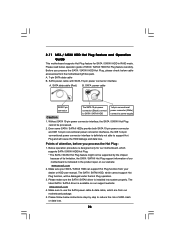
...-pin power cable connector (Black) end to SATA / SATAII HDD. Step 2 Unplug SATA 15-pin power cable connector (Black) from SATA / SATAII HDD side. the motherboard's SATAII connector. How to Hot Unplug a SATA / SATAII HDD: Points of attention, before you process the Hot Plug: Please do follow below instruction sequence to...
...-pin power cable connector (Black) end to SATA / SATAII HDD. Step 2 Unplug SATA 15-pin power cable connector (Black) from SATA / SATAII HDD side. the motherboard's SATAII connector. How to Hot Unplug a SATA / SATAII HDD: Points of attention, before you process the Hot Plug: Please do follow below instruction sequence to...
User Manual
Page 29
Therefore, CPU FSB is untied during overclocking, FSB enjoys better margin due to [CPU, PCIE, Async.]. 2.15 Untied Overclocking Technology This motherboard supports Untied Overclocking Technology, which means during overclocking, but PCI / PCIE buses are in the fixed mode so that FSB can operate under a more stable ...
Therefore, CPU FSB is untied during overclocking, FSB enjoys better margin due to [CPU, PCIE, Async.]. 2.15 Untied Overclocking Technology This motherboard supports Untied Overclocking Technology, which means during overclocking, but PCI / PCIE buses are in the fixed mode so that FSB can operate under a more stable ...
User Manual
Page 30
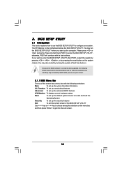
... Menu Bar The top of the screen has a menu bar with its test routines. You may also restart by pressing the reset button on the motherboard stores the BIOS SETUP UTILITY. Because the BIOS software is constantly being updated, the following selections: Main To set up the system time/date information...
... Menu Bar The top of the screen has a menu bar with its test routines. You may also restart by pressing the reset button on the motherboard stores the BIOS SETUP UTILITY. Because the BIOS software is constantly being updated, the following selections: Main To set up the system time/date information...


