User Manual
Page 4
3.4.4 Storage Configuration 43 3.4.5 PCIPnP Configuration 45 3.4.6 Floppy Configuration 46 3.4.7 Super IO Configuration 46 3.4.8 USB Configuration 48 3.5 Hardware Health Event Monitoring Screen 49 3.6 Boot Screen 50 3.6.1 Boot Settings Configuration 50 3.7 Security Screen 51 3.8 Exit Screen 52 4 . Software Support 53 4.1 Install Operating System 53 4.2 Support CD Information 53 4.2.1 Running Support CD 53 4.2.2 Drivers Menu 53 4.2.3 Utilities Menu 53 4.2.4 Contact Information 53 4
3.4.4 Storage Configuration 43 3.4.5 PCIPnP Configuration 45 3.4.6 Floppy Configuration 46 3.4.7 Super IO Configuration 46 3.4.8 USB Configuration 48 3.5 Hardware Health Event Monitoring Screen 49 3.6 Boot Screen 50 3.6.1 Boot Settings Configuration 50 3.7 Security Screen 51 3.8 Exit Screen 52 4 . Software Support 53 4.1 Install Operating System 53 4.2 Support CD Information 53 4.2.1 Running Support CD 53 4.2.2 Drivers Menu 53 4.2.3 Utilities Menu 53 4.2.4 Contact Information 53 4
User Manual
Page 5
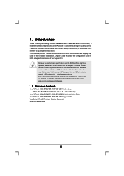
... One ASRock N68-GS3 UCC / N68-S3 UCC Motherboard (Micro ATX Form Factor: 9.6-in x 7.0-in, 24.4 cm x 17.8 cm) One ASRock N68-GS3 UCC / N68-S3 UCC Quick Installation Guide One ASRock N68-GS3 UCC / N68-S3 UCC Support CD Two Serial ATA (SATA) Data Cables (Optional) One I/O Panel Shield 5 1. ASRock website http://www.asrock.com If you are using. In this motherboard, please visit our website for purchasing ASRock N68-GS3 UCC / N68-S3 UCC motherboard...
... One ASRock N68-GS3 UCC / N68-S3 UCC Motherboard (Micro ATX Form Factor: 9.6-in x 7.0-in, 24.4 cm x 17.8 cm) One ASRock N68-GS3 UCC / N68-S3 UCC Quick Installation Guide One ASRock N68-GS3 UCC / N68-S3 UCC Support CD Two Serial ATA (SATA) Data Cables (Optional) One I/O Panel Shield 5 1. ASRock website http://www.asrock.com If you are using. In this motherboard, please visit our website for purchasing ASRock N68-GS3 UCC / N68-S3 UCC motherboard...
User Manual
Page 6
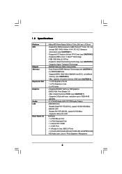
... - 4 x Ready-to 1920x1440 @ 60Hz - 5.1 CH HD Audio (VIA® VT1705 Audio Codec) - Supports UCC feature (Unlock CPU Core) (see CAUTION 3) - Supports Untied Overclocking Technology (see CAUTION 2) - Supports Hyper-Transport Technology - DX9.0 VGA, Pixel Shader 3.0 - N68-S3 UCC Realtek PHY RTL8201EL, speed 10/100 Mb/s - Support DDR3 1600/1333/1066/800 non-ECC, un-buffered memory (see CAUTION 4) - 2 x DDR3...
... - 4 x Ready-to 1920x1440 @ 60Hz - 5.1 CH HD Audio (VIA® VT1705 Audio Codec) - Supports UCC feature (Unlock CPU Core) (see CAUTION 3) - Supports Untied Overclocking Technology (see CAUTION 2) - Supports Hyper-Transport Technology - DX9.0 VGA, Pixel Shader 3.0 - N68-S3 UCC Realtek PHY RTL8201EL, speed 10/100 Mb/s - Support DDR3 1600/1333/1066/800 non-ECC, un-buffered memory (see CAUTION 4) - 2 x DDR3...
User Manual
Page 7
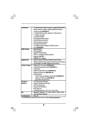
.../Chassis FAN connector - 24 pin ATX power connector - 4 pin 12V power connector - SMBIOS 2.3.1 Support Support CD - Instant Boot - ASRock OC Tuner (see CAUTION 15) - AMI Legal BIOS - Supports jumperfree - Front panel audio header - 2 x USB 2.0 headers (support 4 USB 2.0 ports) (see CAUTION 8) - 1 x ATA133 IDE connector (supports 2 x IDE devices) - 1 x Floppy connector - 1 x Print port header - Hybrid Booster: - Connector - 4 x Serial ATAII...
.../Chassis FAN connector - 24 pin ATX power connector - 4 pin 12V power connector - SMBIOS 2.3.1 Support Support CD - Instant Boot - ASRock OC Tuner (see CAUTION 15) - AMI Legal BIOS - Supports jumperfree - Front panel audio header - 2 x USB 2.0 headers (support 4 USB 2.0 ports) (see CAUTION 8) - 1 x ATA133 IDE connector (supports 2 x IDE devices) - 1 x Floppy connector - 1 x Print port header - Hybrid Booster: - Connector - 4 x Serial ATAII...
User Manual
Page 8
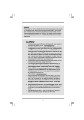
...setting in addition, not every AM2+ / AM3 CPU can also connect SATA hard disk to adjust your own risk and expense. ASRock website http://www.asrock.com 2. Please be less than 4GB for the reservation for details. 4. If you want to adopt DDR3 1600 memory module .... 8 Before installing SATAII hard disk to enjoy an instant performance boost. Power Management for the compatible memory modules. WARNING Please realize that UCC feature is supported with AM2+ / AM3 CPU only, and in the BIOS, applying Untied Overclocking Technology, or using the thirdparty overclocking tools. CAUTION! 1....
...setting in addition, not every AM2+ / AM3 CPU can also connect SATA hard disk to adjust your own risk and expense. ASRock website http://www.asrock.com 2. Please be less than 4GB for the reservation for details. 4. If you want to adopt DDR3 1600 memory module .... 8 Before installing SATAII hard disk to enjoy an instant performance boost. Power Management for the compatible memory modules. WARNING Please realize that UCC feature is supported with AM2+ / AM3 CPU only, and in the BIOS, applying Untied Overclocking Technology, or using the thirdparty overclocking tools. CAUTION! 1....
User Manual
Page 14
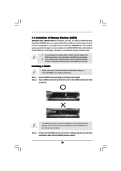
... unable to install a DDR or DDR2 memory module into DDR3 slot;otherwise, this motherboard and DIMM may be damaged. 2. Step 1. 2.3 Installation of Memory Modules (DIMM) N68-GS3 UCC / N68-S3 UCC motherboard provides two 240-pin DDR3 (Double Data Rate 3) DIMM slots, and supports Dual Channel Memory Technology.
... unable to install a DDR or DDR2 memory module into DDR3 slot;otherwise, this motherboard and DIMM may be damaged. 2. Step 1. 2.3 Installation of Memory Modules (DIMM) N68-GS3 UCC / N68-S3 UCC motherboard provides two 240-pin DDR3 (Double Data Rate 3) DIMM slots, and supports Dual Channel Memory Technology.
User Manual
Page 16
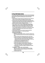
.... Install the NVIDIA® PCI Express VGA card to set up a multi-monitor display. Click the number "2" icon. 16 2.5 Easy Multi Monitor Feature This motherboard supports Multi Monitor upgrade. F. Boot your system. A. G.
.... Install the NVIDIA® PCI Express VGA card to set up a multi-monitor display. Click the number "2" icon. 16 2.5 Easy Multi Monitor Feature This motherboard supports Multi Monitor upgrade. F. Boot your system. A. G.
User Manual
Page 18
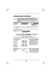
...-pin FLOPPY1) (see p.10, No. 7) Serial ATA (SATA) Data Cable (Optional) SATAII_3 SATAII_1 (PORT 1.0) (PORT 0.0) SATAII_4 SATAII_2 (PORT 1.1) (PORT 0.1) These four Serial ATAII (SATAII) connectors support SATAII or SATA hard disk for the details. 2.7 Onboard Headers and Connectors Onboard headers and connectors are NOT jumpers.
...-pin FLOPPY1) (see p.10, No. 7) Serial ATA (SATA) Data Cable (Optional) SATAII_3 SATAII_1 (PORT 1.0) (PORT 0.0) SATAII_4 SATAII_2 (PORT 1.1) (PORT 0.1) These four Serial ATAII (SATAII) connectors support SATAII or SATA hard disk for the details. 2.7 Onboard Headers and Connectors Onboard headers and connectors are NOT jumpers.
User Manual
Page 19
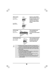
...Audio_L (LIN) to install your system. 2. MIC_RET and OUT_RET are two USB 2.0 headers on the chassis must support HDA to function correctly. Each USB 2.0 header can support two USB 2.0 ports. Connect Mic_IN (MIC) to connect them for the front panel audio cable that allows convenient...ports on the I/O panel, there are for print port cable that allows convenient connection and control of printer devices. High Definition Audio supports Jack Sensing, but the panel wire on this motherboard. Enter Advanced Settings, and then select Chipset Configuration. Set the Front Panel Control...
...Audio_L (LIN) to install your system. 2. MIC_RET and OUT_RET are two USB 2.0 headers on the chassis must support HDA to function correctly. Each USB 2.0 header can support two USB 2.0 ports. Connect Mic_IN (MIC) to connect them for the front panel audio cable that allows convenient...ports on the I/O panel, there are for print port cable that allows convenient connection and control of printer devices. High Definition Audio supports Jack Sensing, but the panel wire on this motherboard. Enter Advanced Settings, and then select Chipset Configuration. Set the Front Panel Control...
User Manual
Page 20
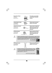
... this motherboard provides 24-pin ATX power connector, 12 24 it to the CPU fan connector on this motherboard provides 4-Pin CPU fan (Quiet Fan) support, the 3-Pin CPU fan still can still work successfully even without the fan speed control function. If you adopt a traditional 20-pin ATX power supply...
... this motherboard provides 24-pin ATX power connector, 12 24 it to the CPU fan connector on this motherboard provides 4-Pin CPU fan (Quiet Fan) support, the 3-Pin CPU fan still can still work successfully even without the fan speed control function. If you adopt a traditional 20-pin ATX power supply...
User Manual
Page 22
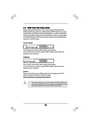
... 3.0Gb/s, please remove the jumpers from pin 5 and pin 6. SAMSUNG 7531 8642 If pin 3 and pin 4 are just for details: http://www.hitachigst.com/hdd/support/download.htm The above examples are shorted, SATA 1.5Gb/s will be enabled. Please visit HITACHI's website for your reference. otherwise, your SATAII hard disk may...
... 3.0Gb/s, please remove the jumpers from pin 5 and pin 6. SAMSUNG 7531 8642 If pin 3 and pin 4 are just for details: http://www.hitachigst.com/hdd/support/download.htm The above examples are shorted, SATA 1.5Gb/s will be enabled. Please visit HITACHI's website for your reference. otherwise, your SATAII hard disk may...
User Manual
Page 23
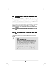
... of the SATA data cable to the SATA / SATAII hard disk. 2 . 1 0 Hot Plug and Hot Swap Functions for SATA / SATAII HDDs This motherboard supports Hot Plug and Hot Swap functions for the action to insert and remove the SATA / SATAII HDDs while the system is still power-on and.... If the SATA / SATAII HDDs are built as RAID1 or RAID 5 then it is called "Hot Plug" for internal storage devices. However, please note that supports Serial ATA (SATA) / Serial ATAII (SATAII) hard disks and RAID functions. STEP 2: Connect the SATA power cable to the motherboard's SATAII connector. If SATA ...
... of the SATA data cable to the SATA / SATAII hard disk. 2 . 1 0 Hot Plug and Hot Swap Functions for SATA / SATAII HDDs This motherboard supports Hot Plug and Hot Swap functions for the action to insert and remove the SATA / SATAII HDDs while the system is still power-on and.... If the SATA / SATAII HDDs are built as RAID1 or RAID 5 then it is called "Hot Plug" for internal storage devices. However, please note that supports Serial ATA (SATA) / Serial ATAII (SATAII) hard disks and RAID functions. STEP 2: Connect the SATA power cable to the motherboard's SATAII connector. If SATA ...
User Manual
Page 24
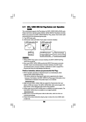
...your dealer or HDD user manual. Please follow below instructions step by the chipset because of its limitation, the SATA / SATAII Hot Plug support information of our motherboard is indicated in RAID mode. Points of attention, before you process the SATA / SATAII HDD Hot Plug, please ...SATA / SATAII HDD Hot Plug feature carefully. Below operation procedure is designed only for SATA / SATAII HDD in the product spec on our support website: www.asrock.com 4. The latest SATA / SATAII driver is installed into system properly. Before you process the Hot Plug: 1. Please make sure the ...
...your dealer or HDD user manual. Please follow below instructions step by the chipset because of its limitation, the SATA / SATAII Hot Plug support information of our motherboard is indicated in RAID mode. Points of attention, before you process the SATA / SATAII HDD Hot Plug, please ...SATA / SATAII HDD Hot Plug feature carefully. Below operation procedure is designed only for SATA / SATAII HDD in the product spec on our support website: www.asrock.com 4. The latest SATA / SATAII driver is installed into system properly. Before you process the Hot Plug: 1. Please make sure the ...
User Manual
Page 26
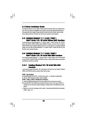
... selection appears. Set the "SATA Operation Mode" option to install Windows® 7 / 7 64-bit / VistaTM / VistaTM 64-bit / XP / XP 64bit on the support CD driver page. STEP 1: Set Up BIOS. Then, the drivers compatible to your system can be auto-detected and listed on your SATA / SATAII HDDs... OS you install. 2.14.1 Installing Windows® XP / XP 64-bit With RAID Functions If you to change the BIOS setting. Insert the ASRock Support CD into your optical drive to boot your optical drive first. 2.12 Driver Installation Guide To install the drivers to your system, please insert the...
... selection appears. Set the "SATA Operation Mode" option to install Windows® 7 / 7 64-bit / VistaTM / VistaTM 64-bit / XP / XP 64bit on the support CD driver page. STEP 1: Set Up BIOS. Then, the drivers compatible to your system can be auto-detected and listed on your SATA / SATAII HDDs... OS you install. 2.14.1 Installing Windows® XP / XP 64-bit With RAID Functions If you to change the BIOS setting. Insert the ASRock Support CD into your optical drive to boot your optical drive first. 2.12 Driver Installation Guide To install the drivers to your system, please insert the...

User Manual
Page 27
...Up BIOS. Enter BIOS SETUP UTILITY Advanced screen Storage Configuration. B. STEP 4: Use "RAID Installation Guide" to check the RAID installation guide in the Support CD for proper configuration. A. Set the "SATA Operation Mode" option to [RAID]. A. Before you start to configure RAID function, you need to ...formatted diskette into floppy drive A: press any key to start to the BIOS RAID installation guide in the following path in the Support CD for proper configuration. Then, please set the RAID configuration by using the Windows RAID installation guide in the following path in...
...Up BIOS. Enter BIOS SETUP UTILITY Advanced screen Storage Configuration. B. STEP 4: Use "RAID Installation Guide" to check the RAID installation guide in the Support CD for proper configuration. A. Set the "SATA Operation Mode" option to [RAID]. A. Before you start to configure RAID function, you need to ...formatted diskette into floppy drive A: press any key to start to the BIOS RAID installation guide in the following path in the Support CD for proper configuration. Then, please set the RAID configuration by using the Windows RAID installation guide in the following path in...
User Manual
Page 28
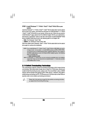
.... 28 NVIDIA® RAID drivers are in BIOS first. NOTE. Then, please set the selection from [Auto] to load RAID driver from ASRock support CD. Before you see "Where do not need to set up "SATA Operation Mode" to [RAID] in the fixed mode so that ,... continue the installation. Please use the native driver to install Windows® 7 / 7 64-bit OS, and then install ASRock All-in-1 driver. 2 . 1 5 Untied Overclocking Technology This motherboard supports Untied Overclocking Technology, which means during overclocking, but PCI / PCIE buses are in the following path in our...
.... 28 NVIDIA® RAID drivers are in BIOS first. NOTE. Then, please set the selection from [Auto] to load RAID driver from ASRock support CD. Before you see "Where do not need to set up "SATA Operation Mode" to [RAID] in the fixed mode so that ,... continue the installation. Please use the native driver to install Windows® 7 / 7 64-bit OS, and then install ASRock All-in-1 driver. 2 . 1 5 Untied Overclocking Technology This motherboard supports Untied Overclocking Technology, which means during overclocking, but PCI / PCIE buses are in the following path in our...
User Manual
Page 33
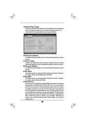
... the value of Processor Frequency and Processor Voltage. CPU Frequency Multiplier For safety and system stability, it is not recommended to [Manual], you can support this item. Configuration options: [Auto], [8 Bit] and [16 Bit]. If it is set to keep the default value for safety and system... stability, it is supported with a better price. It should be noted that UCC feature is recommended to [Auto] by default. Select Screen Select Item Enter Go to [x5 1000 MHz]. Please be done...
... the value of Processor Frequency and Processor Voltage. CPU Frequency Multiplier For safety and system stability, it is not recommended to [Manual], you can support this item. Configuration options: [Auto], [8 Bit] and [16 Bit]. If it is set to keep the default value for safety and system... stability, it is supported with a better price. It should be noted that UCC feature is recommended to [Auto] by default. Select Screen Select Item Enter Go to [x5 1000 MHz]. Please be done...
User Manual
Page 39
Configuration options: [Auto], [Enabled] and [Disabled]. Enhance Halt State All processors support the Halt State (C1). If you install Windows® VistaTM and want to enable this function, please set this item to [Disable] if above issue ..., American Megatrends, Inc. The C1 state is [Auto]. Cool 'n' Quiet Use this item to [Enabled]. The default value is supported through the native processor instructions HLT and MWAIT and requires no hardware support from the chipset. Please set this item to enable or disable AMD's Cool 'n' QuietTM technology. Secure Virtual Machine When...
Configuration options: [Auto], [Enabled] and [Disabled]. Enhance Halt State All processors support the Halt State (C1). If you install Windows® VistaTM and want to enable this function, please set this item to [Disable] if above issue ..., American Megatrends, Inc. The C1 state is [Auto]. Cool 'n' Quiet Use this item to [Enabled]. The default value is supported through the native processor instructions HLT and MWAIT and requires no hardware support from the chipset. Please set this item to enable or disable AMD's Cool 'n' QuietTM technology. Secure Virtual Machine When...
User Manual
Page 41
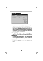
... BIOS SETUP UTILITY Advanced ACPI Settings Suspend To RAM Check Ready Bit Away Mode Support Restore on AC/Power Loss This allows you set the power state after an unexpected AC/power loss. Away... Mode Support Use this item to select whether to auto-detect or disable the Suspend-to turn on...PS/2 Keyboard Power On Use this item to enable or disable Ring-In signals to enable or disable Away Mode support under Windows® XP Media Center OS. If you to set this item to [Disabled], the function "Repost...
... BIOS SETUP UTILITY Advanced ACPI Settings Suspend To RAM Check Ready Bit Away Mode Support Restore on AC/Power Loss This allows you set the power state after an unexpected AC/power loss. Away... Mode Support Use this item to select whether to auto-detect or disable the Suspend-to turn on...PS/2 Keyboard Power On Use this item to enable or disable Ring-In signals to enable or disable Away Mode support under Windows® XP Media Center OS. If you to set this item to [Disabled], the function "Repost...
User Manual
Page 43
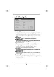
... UTILITY Advanced IDE Master Device Vendor Size LBA Mode Block Mode PIO Mode Async DMA Ultra DMA S.M.A.R.T. :Hard Disk :MAXTOR 6L080J4 :80.0 GB :Supported :16Sectors :4 :MultiWord DMA-2 :Ultra DMA-6 :Supported Type LBA/Large Mode Block (Multi-Sector Transfer) PIO Mode DMA Mode S.M.A.R.T. 32Bit Data Transfer [Auto] [Auto] [Auto] [Auto] [Auto] [Disabled] [Disabled...
... UTILITY Advanced IDE Master Device Vendor Size LBA Mode Block Mode PIO Mode Async DMA Ultra DMA S.M.A.R.T. :Hard Disk :MAXTOR 6L080J4 :80.0 GB :Supported :16Sectors :4 :MultiWord DMA-2 :Ultra DMA-6 :Supported Type LBA/Large Mode Block (Multi-Sector Transfer) PIO Mode DMA Mode S.M.A.R.T. 32Bit Data Transfer [Auto] [Auto] [Auto] [Auto] [Auto] [Disabled] [Disabled...


