User Manual
Page 3
Introduction 5 1.1 Package Contents 5 1.2 Specifications 6 1.3 Motherboard Layout 10 1.4 I/O Panel 11 2 . BIOS SETUP UTILITY 29 3.1 Introduction 29 3.1.1 BIOS Menu Bar 29 3.1.2 Navigation Keys 30 3.2 Main Screen 30 3.3 OC Tweaker Screen 32 3.4 Advanced Screen... 2.3 Installation of Memory Modules (DIMM 14 2.4 Expansion Slots (PCI and PCI Express Slots 15 2.5 Easy Multi Monitor Feature 16 2.6 Jumpers Setup 17 2.7 Onboard Headers and Connectors 18 2.8 SATAII Hard Disk Setup Guide 22 2.9 Serial ATA (SATA) / Serial ATAII (SATAII) Hard Disks Installation 23 2.10 Hot Plug and Hot...
Introduction 5 1.1 Package Contents 5 1.2 Specifications 6 1.3 Motherboard Layout 10 1.4 I/O Panel 11 2 . BIOS SETUP UTILITY 29 3.1 Introduction 29 3.1.1 BIOS Menu Bar 29 3.1.2 Navigation Keys 30 3.2 Main Screen 30 3.3 OC Tweaker Screen 32 3.4 Advanced Screen... 2.3 Installation of Memory Modules (DIMM 14 2.4 Expansion Slots (PCI and PCI Express Slots 15 2.5 Easy Multi Monitor Feature 16 2.6 Jumpers Setup 17 2.7 Onboard Headers and Connectors 18 2.8 SATAII Hard Disk Setup Guide 22 2.9 Serial ATA (SATA) / Serial ATAII (SATAII) Hard Disks Installation 23 2.10 Hot Plug and Hot...
User Manual
Page 7
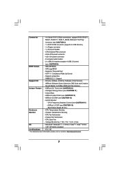
... / XP 64-bit compliant Certifications - Instant Boot - FCC, CE * For detailed product information, please visit our website: http://www.asrock.com 7 CPU/Chassis FAN connector - 24 pin ATX power connector - 4 pin 12V power connector - Front panel audio header - 2 x USB 2.0 headers (support 4 USB 2.0 ports) (see CAUTION 15) - ASRock U-COP (see CAUTION 9) BIOS Feature - 4Mb AMI BIOS -
... / XP 64-bit compliant Certifications - Instant Boot - FCC, CE * For detailed product information, please visit our website: http://www.asrock.com 7 CPU/Chassis FAN connector - 24 pin ATX power connector - 4 pin 12V power connector - Front panel audio header - 2 x USB 2.0 headers (support 4 USB 2.0 ports) (see CAUTION 15) - ASRock U-COP (see CAUTION 9) BIOS Feature - 4Mb AMI BIOS -
User Manual
Page 10
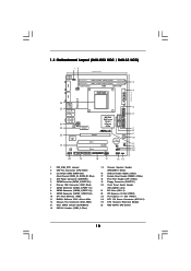
... 13 Clear CMOS Jumper (CLRCMOS1) 14 USB 2.0 Header (USB4_5, Blue) 15 Chassis Speaker Header (SPEAKER 1, White) 16 USB 2.0 Header (USB6_7, Blue) 17 System Panel Header (PANEL1, White) 18 Print Port Header (LPT1, White) 19 Floppy Connector (FLOPPY1) 20 Front Panel Audio Header (HD_AUDIO1, Lime) 21 PCI Slots (PCI1- 2)... 22 PCI Express x16 Slot (PCIE2) 23 PCI Express x1 Slot (PCIE1) 24 ATX 12V Power Connector (ATX12V1) 25 CPU Heatsink Retention Module 26 AM3 938-Pin CPU Socket 10 1.3 Motherboard Layout (N68-GS3 UCC / N68-S3 UCC) ...
... 13 Clear CMOS Jumper (CLRCMOS1) 14 USB 2.0 Header (USB4_5, Blue) 15 Chassis Speaker Header (SPEAKER 1, White) 16 USB 2.0 Header (USB6_7, Blue) 17 System Panel Header (PANEL1, White) 18 Print Port Header (LPT1, White) 19 Floppy Connector (FLOPPY1) 20 Front Panel Audio Header (HD_AUDIO1, Lime) 21 PCI Slots (PCI1- 2)... 22 PCI Express x16 Slot (PCIE2) 23 PCI Express x1 Slot (PCIE1) 24 ATX 12V Power Connector (ATX12V1) 25 CPU Heatsink Retention Module 26 AM3 938-Pin CPU Socket 10 1.3 Motherboard Layout (N68-GS3 UCC / N68-S3 UCC) ...
User Manual
Page 11
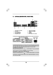
...you will find "VIA HD Audio Deck" tool on the bottom. Then you are allowed to the front panel audio header. LAN Port LED Indications Activity/Link LED SPEED LED Status Description Status Description ACT/LINK SPEED LED LED Off... Deck" icon , and click "Speaker". In "Advanced Options" screen, select "Independent Headphone", and click "OK" to save your system. Click "Power" to save your change . 1.4 I/O Panel (N68-GS3 UCC / N68-S3 UCC) 1 2 3 4 5 10 9 8 1 PS/2 Mouse Port (Green) 2 RJ-45 Port 3 Line In (Light Blue) 4 Front Speaker (Lime) * 5 Microphone (Pink) 7 6...
...you will find "VIA HD Audio Deck" tool on the bottom. Then you are allowed to the front panel audio header. LAN Port LED Indications Activity/Link LED SPEED LED Status Description Status Description ACT/LINK SPEED LED LED Off... Deck" icon , and click "Speaker". In "Advanced Options" screen, select "Independent Headphone", and click "OK" to save your system. Click "Power" to save your change . 1.4 I/O Panel (N68-GS3 UCC / N68-S3 UCC) 1 2 3 4 5 10 9 8 1 PS/2 Mouse Port (Green) 2 RJ-45 Port 3 Line In (Light Blue) 4 Front Speaker (Lime) * 5 Microphone (Pink) 7 6...

User Manual
Page 19
...D. You don't need to Ground (GND). E. Connect Ground (GND) to connect them for AC'97 audio panel. Each USB 2.0 header can support two USB 2.0 ports. Front Panel Audio Header (9-pin HD_AUDIO1) (see p.10, No. 20) GND PRESENCE# MIC_RET OUT_RET 1 OUT2_L J_SENSE OUT2_R MIC2_R MIC2_L This...) to MIC2_L. Enter BIOS Setup Utility. MIC_RET and OUT_RET are two USB 2.0 headers on the chassis must support HDA to the front panel audio header as below: A. Enter Advanced Settings, and then select Chipset Configuration. USB 2.0 Headers (9-pin USB6_7) (see p.10 No. 16) (9-pin USB4_5) (see p.10...
...D. You don't need to Ground (GND). E. Connect Ground (GND) to connect them for AC'97 audio panel. Each USB 2.0 header can support two USB 2.0 ports. Front Panel Audio Header (9-pin HD_AUDIO1) (see p.10, No. 20) GND PRESENCE# MIC_RET OUT_RET 1 OUT2_L J_SENSE OUT2_R MIC2_R MIC2_L This...) to MIC2_L. Enter BIOS Setup Utility. MIC_RET and OUT_RET are two USB 2.0 headers on the chassis must support HDA to the front panel audio header as below: A. Enter Advanced Settings, and then select Chipset Configuration. USB 2.0 Headers (9-pin USB6_7) (see p.10 No. 16) (9-pin USB4_5) (see p.10...
User Manual
Page 20
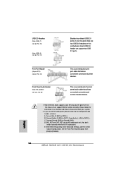
... CPU fan still can still work successfully even without the fan speed control function. Please connect a chassis fan cable to this header. Pin 1-3 Connected 3-Pin Fan Installation ATX Power Connector (24-pin ATXPWR1) (see p.10 No. 4) 12 24 Please ...) PLED+ PLEDPWRBTN# GND 1 DUMMY RESET# GND HDLEDHDLED+ 1 SPEAKER DUMMY DUMMY +5V GND +12V CHA_FAN_SPEED This header accommodates several system front panel functions. System Panel Header (9-pin PANEL1) (see p.10 No. 17) Chassis Speaker Header (4-pin SPEAKER 1) (see p.10 No. 15) Chassis Fan Connector (3-pin CHA_FAN1) (see p.10 No. 2)...
... CPU fan still can still work successfully even without the fan speed control function. Please connect a chassis fan cable to this header. Pin 1-3 Connected 3-Pin Fan Installation ATX Power Connector (24-pin ATXPWR1) (see p.10 No. 4) 12 24 Please ...) PLED+ PLEDPWRBTN# GND 1 DUMMY RESET# GND HDLEDHDLED+ 1 SPEAKER DUMMY DUMMY +5V GND +12V CHA_FAN_SPEED This header accommodates several system front panel functions. System Panel Header (9-pin PANEL1) (see p.10 No. 17) Chassis Speaker Header (4-pin SPEAKER 1) (see p.10 No. 15) Chassis Fan Connector (3-pin CHA_FAN1) (see p.10 No. 2)...

Quick Installation Guide
Page 2
... Floppy Connector (FLOPPY1) 20 Front Panel Audio Header (HD_AUDIO1, Lime) 21 PCI Slots (PCI1- 2) 22 PCI Express x16 Slot (PCIE2) 23 PCI Express x1 Slot (PCIE1) 24 ATX 12V Power Connector (ATX12V1) 25 CPU Heatsink Retention Module 26 AM3 938-Pin CPU Socket 2 ASRock N68-GS3 UCC / N68-S3 UCC Motherboard Motherboard Layout (N68-GS3 UCC / N68-S3 UCC) English 1 PS2_USB_PW1 Jumper 2 CPU...
... Floppy Connector (FLOPPY1) 20 Front Panel Audio Header (HD_AUDIO1, Lime) 21 PCI Slots (PCI1- 2) 22 PCI Express x16 Slot (PCIE2) 23 PCI Express x1 Slot (PCIE1) 24 ATX 12V Power Connector (ATX12V1) 25 CPU Heatsink Retention Module 26 AM3 938-Pin CPU Socket 2 ASRock N68-GS3 UCC / N68-S3 UCC Motherboard Motherboard Layout (N68-GS3 UCC / N68-S3 UCC) English 1 PS2_USB_PW1 Jumper 2 CPU...

Quick Installation Guide
Page 3
... click "VIA HD Audio Deck" icon , and click "Advanced Options" on the left side on your change . 3 ASRock N68-GS3 UCC / N68-S3 UCC Motherboard English Then you are allowed to save your system. LAN Port LED Indications Activity/Link LED SPEED LED Status Description Status...Streaming function, you need to connect a front panel audio cable to save your change . Click "Power" to the front panel audio header. Please follow below instructions according to the table below for the LAN port LED indications. I/O Panel (N68-GS3 UCC / N68-S3 UCC) 1 PS/2 Mouse Port (Green) 2 RJ...
... click "VIA HD Audio Deck" icon , and click "Advanced Options" on the left side on your change . 3 ASRock N68-GS3 UCC / N68-S3 UCC Motherboard English Then you are allowed to save your system. LAN Port LED Indications Activity/Link LED SPEED LED Status Description Status...Streaming function, you need to connect a front panel audio cable to save your change . Click "Power" to the front panel audio header. Please follow below instructions according to the table below for the LAN port LED indications. I/O Panel (N68-GS3 UCC / N68-S3 UCC) 1 PS/2 Mouse Port (Green) 2 RJ...

Quick Installation Guide
Page 6
...and Play" - Instant Boot - Chassis Fan Tachometer - CPU Frequency Stepless Control (see CAUTION 13) - Front panel audio header - 2 x USB 2.0 headers (support 4 USB 2.0 ports) (see CAUTION 12) - ASRock Instant Flash (see CAUTION 9) BIOS Feature - 4Mb AMI BIOS - CPU Quiet Fan - Voltage Monitoring: +12V...- FCC, CE * For detailed product information, please visit our website: http://www.asrock.com English 6 ASRock N68-GS3 UCC / N68-S3 UCC Motherboard Hybrid Booster: - CPU/Chassis FAN connector - 24 pin ATX power connector - 4 pin 12V power connector -
...and Play" - Instant Boot - Chassis Fan Tachometer - CPU Frequency Stepless Control (see CAUTION 13) - Front panel audio header - 2 x USB 2.0 headers (support 4 USB 2.0 ports) (see CAUTION 12) - ASRock Instant Flash (see CAUTION 9) BIOS Feature - 4Mb AMI BIOS - CPU Quiet Fan - Voltage Monitoring: +12V...- FCC, CE * For detailed product information, please visit our website: http://www.asrock.com English 6 ASRock N68-GS3 UCC / N68-S3 UCC Motherboard Hybrid Booster: - CPU/Chassis FAN connector - 24 pin ATX power connector - 4 pin 12V power connector -
Quick Installation Guide
Page 16
... (GND) to [Enabled]. 16 ASRock N68-GS3 UCC / N68-S3 UCC Motherboard English D. You don't need to connect them for HD audio panel only. Set the Front Panel Control option from [Auto] to Ground (GND). USB 2.0 Headers (9-pin USB6_7) (see p.2 No. 16) (9-pin USB4_5) (see p.2 No. 14) Besides four default USB 2.0 ports on the I/O panel, there are for AC'97...
... (GND) to [Enabled]. 16 ASRock N68-GS3 UCC / N68-S3 UCC Motherboard English D. You don't need to connect them for HD audio panel only. Set the Front Panel Control option from [Auto] to Ground (GND). USB 2.0 Headers (9-pin USB6_7) (see p.2 No. 16) (9-pin USB4_5) (see p.2 No. 14) Besides four default USB 2.0 ports on the I/O panel, there are for AC'97...
Quick Installation Guide
Page 17
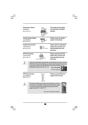
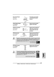
...-pin ATX power supply, please plug your power supply along with Pin 1 and Pin 13. 20-Pin ATX Power Supply Installation 1 13 English 17 ASRock N68-GS3 UCC / N68-S3 UCC Motherboard System Panel Header (9-pin PANEL1) (see p.2 No. 2) 4 3 2 1 Please connect the CPU fan cable to this motherboard provides 4-Pin CPU fan (Quiet Fan) support, the 3-Pin CPU... Fan Connector (3-pin CHA_FAN1) (see p.2 No. 15) Please connect the chassis speaker to the ground pin. CPU Fan Connector (4-pin CPU_FAN1) (see p.2 No. 17) This header accommodates several system front panel functions.
...-pin ATX power supply, please plug your power supply along with Pin 1 and Pin 13. 20-Pin ATX Power Supply Installation 1 13 English 17 ASRock N68-GS3 UCC / N68-S3 UCC Motherboard System Panel Header (9-pin PANEL1) (see p.2 No. 2) 4 3 2 1 Please connect the CPU fan cable to this motherboard provides 4-Pin CPU fan (Quiet Fan) support, the 3-Pin CPU... Fan Connector (3-pin CHA_FAN1) (see p.2 No. 15) Please connect the chassis speaker to the ground pin. CPU Fan Connector (4-pin CPU_FAN1) (see p.2 No. 17) This header accommodates several system front panel functions.


