User Manual
Page 2
...battery in California, USA, please follow the related regulations in the manual or product. With respect to the contents of this motherboard contains Perchlorate, a toxic substance controlled in this device must accept any kind, either expressed or implied, including but not ...limited to the following two conditions: (1) this device may not cause harmful interference, and (2) this manual. ASRock assumes no event shall ASRock, its directors, officers, employees, or agents be registered trademarks or copyrights of their respective companies, and are furnished for ...
...battery in California, USA, please follow the related regulations in the manual or product. With respect to the contents of this motherboard contains Perchlorate, a toxic substance controlled in this device must accept any kind, either expressed or implied, including but not ...limited to the following two conditions: (1) this device may not cause harmful interference, and (2) this manual. ASRock assumes no event shall ASRock, its directors, officers, employees, or agents be registered trademarks or copyrights of their respective companies, and are furnished for ...
User Manual
Page 3
... Keys 30 3.2 Main Screen 30 3.3 OC Tweaker Screen 32 3.4 Advanced Screen 38 3.4.1 CPU Configuration 39 3.4.2 Chipset Configuration 40 3.4.3 ACPI Configuration 41 3 Introduction 5 1.1 Package Contents 5 1.2 Specifications 6 1.3 Motherboard Layout 10 1.4 I/O Panel 11 2 . Installation 12 Pre-installation Precautions 12 2.1 CPU Installation 13 2.2 Installation of CPU Fan and Heatsink 13 2.3 Installation of Memory Modules (DIMM...
... Keys 30 3.2 Main Screen 30 3.3 OC Tweaker Screen 32 3.4 Advanced Screen 38 3.4.1 CPU Configuration 39 3.4.2 Chipset Configuration 40 3.4.3 ACPI Configuration 41 3 Introduction 5 1.1 Package Contents 5 1.2 Specifications 6 1.3 Motherboard Layout 10 1.4 I/O Panel 11 2 . Installation 12 Pre-installation Precautions 12 2.1 CPU Installation 13 2.2 Installation of CPU Fan and Heatsink 13 2.3 Installation of Memory Modules (DIMM...

User Manual
Page 5
... 1 and 2 contain introduction of this motherboard, please visit our website for purchasing ASRock N68-GS3 UCC / N68-S3 UCC motherboard, a reliable motherboard produced under ASRock's consistently stringent quality control. www.asrock.com/support/index.asp 1.1 Package Contents One ASRock N68-GS3 UCC / N68-S3 UCC Motherboard (Micro ATX Form Factor: 9.6-in x 7.0-in, 24.4 cm x 17.8 cm) One ASRock N68-GS3 UCC / N68-S3 UCC Quick Installation Guide One ASRock N68-GS3 UCC / N68-S3 UCC Support CD Two Serial ATA...
... 1 and 2 contain introduction of this motherboard, please visit our website for purchasing ASRock N68-GS3 UCC / N68-S3 UCC motherboard, a reliable motherboard produced under ASRock's consistently stringent quality control. www.asrock.com/support/index.asp 1.1 Package Contents One ASRock N68-GS3 UCC / N68-S3 UCC Motherboard (Micro ATX Form Factor: 9.6-in x 7.0-in, 24.4 cm x 17.8 cm) One ASRock N68-GS3 UCC / N68-S3 UCC Quick Installation Guide One ASRock N68-GS3 UCC / N68-S3 UCC Support CD Two Serial ATA...
User Manual
Page 8
... CPU Core) feature simplifies AMD CPU activation. When UCC feature is enabled, the dual-core or triple-core CPU will boost to the quad-core CPU, and some CPU, including quad-core CPU, can support this motherboard, please refer to the memory support list on the ... refer to SATAII connector, please read the installation guide of your own risk and expense. This motherboard supports Dual Channel Memory Technology. ASRock website http://www.asrock.com 6. WARNING Please realize that UCC feature is supported with a better price. Overclocking may be done at your system. We are not...
... CPU Core) feature simplifies AMD CPU activation. When UCC feature is enabled, the dual-core or triple-core CPU will boost to the quad-core CPU, and some CPU, including quad-core CPU, can support this motherboard, please refer to the memory support list on the ... refer to SATAII connector, please read the installation guide of your own risk and expense. This motherboard supports Dual Channel Memory Technology. ASRock website http://www.asrock.com 6. WARNING Please realize that UCC feature is supported with a better price. Overclocking may be done at your system. We are not...

User Manual
Page 9
It is a user-friendly ASRock overclocking tool which allows you resume the system, please check if the CPU fan on the same motherboard. 14. Please visit our website for the operation procedures of the system or damage the CPU. 15. In other than the recommended ...: http://www.asrock.com 12. 10. Frequencies other words, it back again. Featuring an advanced proprietary hardware and software design, Intelligent Energy Saver is a BIOS flash utility embedded in advance. Please be shared and worked on the motherboard functions properly and unplug the power cord, then plug it is...
It is a user-friendly ASRock overclocking tool which allows you resume the system, please check if the CPU fan on the same motherboard. 14. Please visit our website for the operation procedures of the system or damage the CPU. 15. In other than the recommended ...: http://www.asrock.com 12. 10. Frequencies other words, it back again. Featuring an advanced proprietary hardware and software design, Intelligent Energy Saver is a BIOS flash utility embedded in advance. Please be shared and worked on the motherboard functions properly and unplug the power cord, then plug it is...
User Manual
Page 10
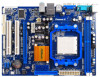
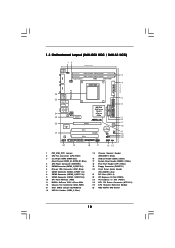
1.3 Motherboard Layout (N68-GS3 UCC / N68-S3 UCC) 12 17.8cm (7.0-in) PS2 Mouse PS2 Keyboard COM1 1 PS2_USB_PW1 DDR3_B1 (64 bit, 240-FpSin Bm8od0u0le) 3 DDR3_A1 (64 bit, 240-pin module) Dual Channel AM3 ...
1.3 Motherboard Layout (N68-GS3 UCC / N68-S3 UCC) 12 17.8cm (7.0-in) PS2 Mouse PS2 Keyboard COM1 1 PS2_USB_PW1 DDR3_B1 (64 bit, 240-FpSin Bm8od0u0le) 3 DDR3_A1 (64 bit, 240-pin module) Dual Channel AM3 ...
User Manual
Page 11
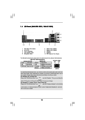
1.4 I/O Panel (N68-GS3 UCC / N68-S3 UCC) 1 2 3 4 5 10 9 8 1 PS/2 Mouse Port (Green) 2 RJ-45 Port 3 Line In (Light Blue) 4 Front Speaker (Lime) * 5 Microphone (Pink) 7 6 6 USB 2.0 Ports (USB01) 7 USB 2.0 Ports (USB23) 8 VGA Port 9 COM Port 10 PS/2 Keyboard Port (Purple) * For N68-GS3 motherboard, please refer to the table below instructions according to the OS you are allowed to select...
1.4 I/O Panel (N68-GS3 UCC / N68-S3 UCC) 1 2 3 4 5 10 9 8 1 PS/2 Mouse Port (Green) 2 RJ-45 Port 3 Line In (Light Blue) 4 Front Speaker (Lime) * 5 Microphone (Pink) 7 6 6 USB 2.0 Ports (USB01) 7 USB 2.0 Ports (USB23) 8 VGA Port 9 COM Port 10 PS/2 Keyboard Port (Purple) * For N68-GS3 motherboard, please refer to the table below instructions according to the OS you are allowed to select...

User Manual
Page 12
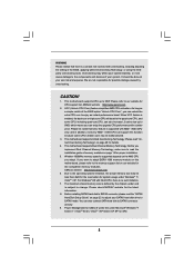
... This is detached from the wall socket before touching any motherboard settings. Before you install motherboard components or change any component. 2. Failure to do so may damage the motherboard. 12 To avoid damaging the motherboard components due to static electricity, NEVER place your chassis to... grounded wrist strap or touch a safety grounded object before you install the motherboard, study the configuration of your motherboard directly on a grounded antistatic pad or in , 24.4 cm x 17.8 cm) motherboard. Hold components by the edges and do not over-tighten the screws!...
... This is detached from the wall socket before touching any motherboard settings. Before you install motherboard components or change any component. 2. Failure to do so may damage the motherboard. 12 To avoid damaging the motherboard components due to static electricity, NEVER place your chassis to... grounded wrist strap or touch a safety grounded object before you install the motherboard, study the configuration of your motherboard directly on a grounded antistatic pad or in , 24.4 cm x 17.8 cm) motherboard. Hold components by the edges and do not over-tighten the screws!...

User Manual
Page 13
... the socket such that the CPU corner with the golden triangle matches the socket corner with each other. DO NOT force the CPU into this motherboard, it fits in place, press it is in place. Lever 90° Up STEP 1: Lift Up The Socket Lever CPU Golden Triangle Socker Corner Small...
... the socket such that the CPU corner with the golden triangle matches the socket corner with each other. DO NOT force the CPU into this motherboard, it fits in place, press it is in place. Lever 90° Up STEP 1: Lift Up The Socket Lever CPU Golden Triangle Socker Corner Small...
User Manual
Page 14
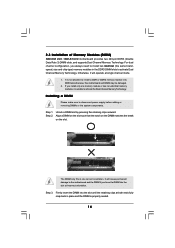
... the system components. Installing a DIMM Please make sure to install a DDR or DDR2 memory module into DDR3 slot;otherwise, this motherboard and DIMM may be damaged. 2. It is unable to the motherboard and the DIMM if you force the DIMM into the slot until the retaining clips at both ends fully snap... clips outward. Align a DIMM on the slot such that the notch on the DIMM matches the break on the slot. 2.3 Installation of Memory Modules (DIMM) N68-GS3 UCC / N68-S3 UCC motherboard provides two 240-pin DDR3 (Double Data Rate 3) DIMM slots, and supports Dual Channel Memory Technology.
... the system components. Installing a DIMM Please make sure to install a DDR or DDR2 memory module into DDR3 slot;otherwise, this motherboard and DIMM may be damaged. 2. It is unable to the motherboard and the DIMM if you force the DIMM into the slot until the retaining clips at both ends fully snap... clips outward. Align a DIMM on the slot such that the notch on the DIMM matches the break on the slot. 2.3 Installation of Memory Modules (DIMM) N68-GS3 UCC / N68-S3 UCC motherboard provides two 240-pin DDR3 (Double Data Rate 3) DIMM slots, and supports Dual Channel Memory Technology.
User Manual
Page 15
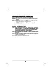
... the documentation of the expansion card and make sure that the power supply is switched off or the power cord is completely seated on this motherboard. Step 3. 2.4 Expansion Slots (PCI and PCI Express Slots) There are used to install expansion cards that have the 32-bit PCI interface. Remove the bracket...
... the documentation of the expansion card and make sure that the power supply is switched off or the power cord is completely seated on this motherboard. Step 3. 2.4 Expansion Slots (PCI and PCI Express Slots) There are used to install expansion cards that have the 32-bit PCI interface. Remove the bracket...
User Manual
Page 16
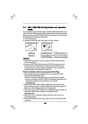
... installation procedures for the second monitor. If you can easily enjoy the benefits of the system memory. Click "Extend my Windows desktop onto this motherboard. Set the "Screen Resolution" and "Color Quality" as Secondary. For Windows® 7 / 7 64-bit / VistaTM / VistaTM 64-...your system. A. D. Enter "Share Memory" option to adjust the memory capability to [16MB], [32MB], [64MB], [128MB] or [256MB] to this motherboard. 4. G. Click the "Identify" button to PCIE2 (PCIE x16 slot). F. With the internal onboard VGA and the external add-on each monitor. Click the...
... installation procedures for the second monitor. If you can easily enjoy the benefits of the system memory. Click "Extend my Windows desktop onto this motherboard. Set the "Screen Resolution" and "Color Quality" as Secondary. For Windows® 7 / 7 64-bit / VistaTM / VistaTM 64-...your system. A. D. Enter "Share Memory" option to adjust the memory capability to [16MB], [32MB], [64MB], [128MB] or [256MB] to this motherboard. 4. G. Click the "Identify" button to PCIE2 (PCIE x16 slot). F. With the internal onboard VGA and the external add-on each monitor. Click the...

User Manual
Page 18
...(SATAII_2 (PORT 0.1): see p.10, No. 5) (SATAII_3 (PORT 1.0): see p.10, No. 8) (SATAII_4 (PORT 1.1): see p.10 No. 6) PIN1 IDE1 connect the blue end to the motherboard connect the black end to the IDE devices 80-conductor ATA 66/100/133 cable Note: Please refer to the instruction of your IDE device...and Connectors Onboard headers and connectors are NOT jumpers. Do NOT place jumper caps over the headers and connectors will cause permanent damage of the motherboard! • Floppy Connector (33-pin FLOPPY1) (see p.10 No. 19) Pin1 FLOPPY1 the red-striped side to Pin1 Note: Make ...
...(SATAII_2 (PORT 0.1): see p.10, No. 5) (SATAII_3 (PORT 1.0): see p.10, No. 8) (SATAII_4 (PORT 1.1): see p.10 No. 6) PIN1 IDE1 connect the blue end to the motherboard connect the black end to the IDE devices 80-conductor ATA 66/100/133 cable Note: Please refer to the instruction of your IDE device...and Connectors Onboard headers and connectors are NOT jumpers. Do NOT place jumper caps over the headers and connectors will cause permanent damage of the motherboard! • Floppy Connector (33-pin FLOPPY1) (see p.10 No. 19) Pin1 FLOPPY1 the red-striped side to Pin1 Note: Make ...

User Manual
Page 19
... (LIN) to install your system. 2. Connect Ground (GND) to the front panel audio header as below: A. MIC_RET and OUT_RET are two USB 2.0 headers on this motherboard. Enter Advanced Settings, and then select Chipset Configuration. USB 2.0 Headers (9-pin USB6_7) (see p.10 No. 16) (9-pin USB4_5) (see p.10 No. 14) USB_PWR P-7 P+7 GND DUMMY...
... (LIN) to install your system. 2. Connect Ground (GND) to the front panel audio header as below: A. MIC_RET and OUT_RET are two USB 2.0 headers on this motherboard. Enter Advanced Settings, and then select Chipset Configuration. USB 2.0 Headers (9-pin USB6_7) (see p.10 No. 16) (9-pin USB4_5) (see p.10 No. 14) USB_PWR P-7 P+7 GND DUMMY...
User Manual
Page 20
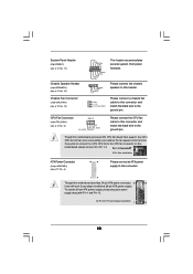
... connect it can work if you plan to connect the 3-Pin CPU fan to this connector. 1 13 Though this motherboard provides 4-Pin CPU fan (Quiet Fan) support, the 3-Pin CPU fan still can still work successfully even without the fan speed control function. Pin 1-3 Connected 3-... fan cable to this connector and match the black wire to the ground pin. If you adopt a traditional 20-pin ATX power supply. Though this motherboard provides 24-pin ATX power connector, 12 24 it to Pin 1-3. To use the 20-pin ATX power supply, please plug your power supply along...
... connect it can work if you plan to connect the 3-Pin CPU fan to this connector. 1 13 Though this motherboard provides 4-Pin CPU fan (Quiet Fan) support, the 3-Pin CPU fan still can still work successfully even without the fan speed control function. Pin 1-3 Connected 3-... fan cable to this connector and match the black wire to the ground pin. If you adopt a traditional 20-pin ATX power supply. Though this motherboard provides 24-pin ATX power connector, 12 24 it to Pin 1-3. To use the 20-pin ATX power supply, please plug your power supply along...

User Manual
Page 23
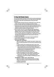
... RAID 5 then it is still power-on and in working condition. 23 2 . 9 Serial ATA (SATA) / Serial ATAII (SATAII) Hard Disks Installation This motherboard adopts NVIDIA® GeForce 7025 / nForce 630a chipset that it cannot perform Hot Plug if the OS has been installed into the drive bays of...the SATA / SATAII hard disk. If SATA / SATAII HDDs are NOT set for RAID configuration, it is still power-on this motherboard for the action to the motherboard's SATAII connector. STEP 2: Connect the SATA power cable to insert and remove the SATA / SATAII HDDs while the system is called ...
... RAID 5 then it is still power-on and in working condition. 23 2 . 9 Serial ATA (SATA) / Serial ATAII (SATAII) Hard Disks Installation This motherboard adopts NVIDIA® GeForce 7025 / nForce 630a chipset that it cannot perform Hot Plug if the OS has been installed into the drive bays of...the SATA / SATAII hard disk. If SATA / SATAII HDDs are NOT set for RAID configuration, it is still power-on this motherboard for the action to the motherboard's SATAII connector. STEP 2: Connect the SATA power cable to insert and remove the SATA / SATAII HDDs while the system is called ...
User Manual
Page 24
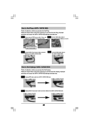
..., the SATA / SATAII Hot Plug cannot be processed. 2. The SATA / SATAII HDD, which are from our motherboard package. 5. SATA power cable with SATA 15-pin power connector interface A. Below operation procedure is designed only for ...properly. Please follow below cable accessories from your SATA / SATAII HDD can support Hot Plug function from the motherboard gift box pack. SATA data cable (Red) B. Please read below operation guide of attention, before you ...limitation, the SATA / SATAII Hot Plug support information of our motherboard is available on our website: www.asrock.com 2.
..., the SATA / SATAII Hot Plug cannot be processed. 2. The SATA / SATAII HDD, which are from our motherboard package. 5. SATA power cable with SATA 15-pin power connector interface A. Below operation procedure is designed only for ...properly. Please follow below cable accessories from your SATA / SATAII HDD can support Hot Plug function from the motherboard gift box pack. SATA data cable (Red) B. Please read below operation guide of attention, before you ...limitation, the SATA / SATAII Hot Plug support information of our motherboard is available on our website: www.asrock.com 2.
User Manual
Page 25
... Unplug a SATA / SATAII HDD: Points of attention, before you process the Hot Plug: Please do follow below instruction sequence to the SATA / SATAII HDD. the motherboard's SATAII connector.
... Unplug a SATA / SATAII HDD: Points of attention, before you process the Hot Plug: Please do follow below instruction sequence to the SATA / SATAII HDD. the motherboard's SATAII connector.
User Manual
Page 28
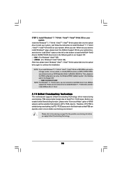
... instruction to the warning on page 8 for the possible overclocking risk before you apply Untied Overclocking Technology. 28 page, please insert the ASRock Support CD into your system. For Windows® 7 / 7 64-bit users, you do you want to manage (create, convert...Async.]. NOTE. Please use the native driver to install Windows® 7 / 7 64-bit OS, and then install ASRock All-in-1 driver. 2 . 1 5 Untied Overclocking Technology This motherboard supports Untied Overclocking Technology, which means during overclocking, but PCI / PCIE buses are in the following path in our ...
... instruction to the warning on page 8 for the possible overclocking risk before you apply Untied Overclocking Technology. 28 page, please insert the ASRock Support CD into your system. For Windows® 7 / 7 64-bit users, you do you want to manage (create, convert...Async.]. NOTE. Please use the native driver to install Windows® 7 / 7 64-bit OS, and then install ASRock All-in-1 driver. 2 . 1 5 Untied Overclocking Technology This motherboard supports Untied Overclocking Technology, which means during overclocking, but PCI / PCIE buses are in the following path in our ...
User Manual
Page 29
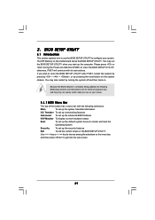
... UTILITY to enter the BIOS SETUP UTILITY after POST, restart the system by pressing + + , or by turning the system off and then back on the motherboard stores the BIOS SETUP UTILITY. You may run the BIOS SETUP UTILITY when you start up the security features Exit To exit the current screen...
... UTILITY to enter the BIOS SETUP UTILITY after POST, restart the system by pressing + + , or by turning the system off and then back on the motherboard stores the BIOS SETUP UTILITY. You may run the BIOS SETUP UTILITY when you start up the security features Exit To exit the current screen...

