User Manual
Page 6
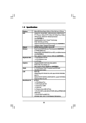
...® GeForce 6150SE / nForce 430 - Integrated NVIDIA® GeForce6-class graphics - shared memory 256MB (see CAUTION 4) - N61P-GS Realtek Giga PHY RTL8211CL-GR, speed 10/100/1000 Mb/s - 1.2 Specifications Platform CPU Chipset Memory Expansion Slot Graphics Audio LAN Rear Panel I /O Panel - 1 x PS/2 Mouse Port - 1 x PS/2 Keyboard Port - 1 x Serial Port: COM1 - 1 x VGA Port...
...® GeForce 6150SE / nForce 430 - Integrated NVIDIA® GeForce6-class graphics - shared memory 256MB (see CAUTION 4) - N61P-GS Realtek Giga PHY RTL8211CL-GR, speed 10/100/1000 Mb/s - 1.2 Specifications Platform CPU Chipset Memory Expansion Slot Graphics Audio LAN Rear Panel I /O Panel - 1 x PS/2 Mouse Port - 1 x PS/2 Keyboard Port - 1 x Serial Port: COM1 - 1 x VGA Port...
User Manual
Page 7
... 4 pin 12V power connector - Supports Smart BIOS Support CD - Intelligent Energy Saver (see CAUTION 9) - ASRock U-COP (see CAUTION 13) Hardware - ASRock AM2 Boost: ASRock Patented Technology to boost memory performance up to 12.5% (see CAUTION 12) - Connector - 4 x Serial...bit compliant Certifications - Supports jumperfree - Hybrid Booster: - FCC, CE * For detailed product information, please visit our website: http://www.asrock.com 7 Front panel audio header - 2 x USB 2.0 headers (support 4 USB 2.0 ports) (see CAUTION 8) BIOS Feature - 4Mb AMI BIOS - Boot ...
... 4 pin 12V power connector - Supports Smart BIOS Support CD - Intelligent Energy Saver (see CAUTION 9) - ASRock U-COP (see CAUTION 13) Hardware - ASRock AM2 Boost: ASRock Patented Technology to boost memory performance up to 12.5% (see CAUTION 12) - Connector - 4 x Serial...bit compliant Certifications - Supports jumperfree - Hybrid Booster: - FCC, CE * For detailed product information, please visit our website: http://www.asrock.com 7 Front panel audio header - 2 x USB 2.0 headers (support 4 USB 2.0 ports) (see CAUTION 8) BIOS Feature - 4Mb AMI BIOS - Boot ...
User Manual
Page 10
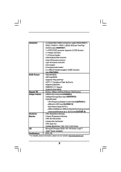
...Connector (SATAII_2 (PORT1))19 Floppy Connector (FLOPPY1) 6 Primary IDE Connector (IDE1, Blue) 20 Internal Audio Connector: CD1 (Black) 7 Fourth SATAII Connector (SATAII_4 (PORT3)) 21 Front Panel Audio Header 8 Third SATAII Connector (SATAII_3 (PORT2)) (HD_AUDIO1, Lime) 9 Primary SATAII Connector (SATAII_1 (PORT0...PHY IDE1 NVIDIA GeForce 6150SE / nForce 430 SATAII_3 (PORT 2) SATAII_1 (PORT 0) SATAII_4 (PORT 3) SATAII_2 (PORT 1) RAID Super I/O AUDIO CODEC CD1 HD_AUDIO1 1 21 20 FLOPPY1 19 PCIE2 PCI1 PCI2 LPT1 1 RoHS 4Mb BIOS CMOS BATTERY CLRCMOS1 1 CHA_FAN1 1 USB4_5 PANEL ...
...Connector (SATAII_2 (PORT1))19 Floppy Connector (FLOPPY1) 6 Primary IDE Connector (IDE1, Blue) 20 Internal Audio Connector: CD1 (Black) 7 Fourth SATAII Connector (SATAII_4 (PORT3)) 21 Front Panel Audio Header 8 Third SATAII Connector (SATAII_3 (PORT2)) (HD_AUDIO1, Lime) 9 Primary SATAII Connector (SATAII_1 (PORT0...PHY IDE1 NVIDIA GeForce 6150SE / nForce 430 SATAII_3 (PORT 2) SATAII_1 (PORT 0) SATAII_4 (PORT 3) SATAII_2 (PORT 1) RAID Super I/O AUDIO CODEC CD1 HD_AUDIO1 1 21 20 FLOPPY1 19 PCIE2 PCI1 PCI2 LPT1 1 RoHS 4Mb BIOS CMOS BATTERY CLRCMOS1 1 CHA_FAN1 1 USB4_5 PANEL ...
User Manual
Page 11
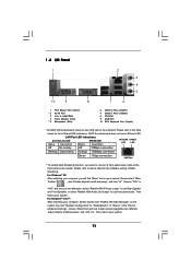
...LAN Port ** To enable Multi-Streaming function, you will find "Mixer" tool on your computer, please double-click "Realtek HD Audio Manager" on the system tray. N61P-S motherboard does not have LAN port LED. Please select "Mixer ToolBox" , click "Enable playback multi-streaming", and click "ok...". For Windows® XP: After restarting your computer, you need to connect a front panel audio cable to "Quadraphonic" or "Stereo". Please...
...LAN Port ** To enable Multi-Streaming function, you will find "Mixer" tool on your computer, please double-click "Realtek HD Audio Manager" on the system tray. N61P-S motherboard does not have LAN port LED. Please select "Mixer ToolBox" , click "Enable playback multi-streaming", and click "ok...". For Windows® XP: After restarting your computer, you need to connect a front panel audio cable to "Quadraphonic" or "Stereo". Please...

User Manual
Page 19
..., but the panel wire on this motherboard. Connect Mic_IN (MIC) to Ground (GND). Connect Ground (GND) to MIC2_L. D. If you to receive stereo audio input from sound sources such as below: A. Connect Audio_R (RIN) to OUT2_R and Audio_L (LIN) to OUT2_L. Print Port Header (25-pin LPT1) (see...PINIT# SLIN# GND 1 SPD7 SPD6 ACK# SPD5 BUSY SPD4 PE SPD3 SLCT SPD2 SPD1 SPD0 STB# This is an interface for AC'97 audio panel. 19 Front Panel Audio Header (9-pin HD_AUDIO1) (see p.10, No. 21) GND PRESENCE# MIC_RET OUT_RET 1 OUT2_L J_SENSE OUT2_R MIC2_R MIC2_L This is an interface ...
..., but the panel wire on this motherboard. Connect Mic_IN (MIC) to Ground (GND). Connect Ground (GND) to MIC2_L. D. If you to receive stereo audio input from sound sources such as below: A. Connect Audio_R (RIN) to OUT2_R and Audio_L (LIN) to OUT2_L. Print Port Header (25-pin LPT1) (see...PINIT# SLIN# GND 1 SPD7 SPD6 ACK# SPD5 BUSY SPD4 PE SPD3 SLCT SPD2 SPD1 SPD0 STB# This is an interface for AC'97 audio panel. 19 Front Panel Audio Header (9-pin HD_AUDIO1) (see p.10, No. 21) GND PRESENCE# MIC_RET OUT_RET 1 OUT2_L J_SENSE OUT2_R MIC2_R MIC2_L This is an interface ...

User Manual
Page 20
... DUMMY +5V GND +12V CHA_FAN_SPEED This header accommodates several system front panel functions. For Windows® 2000 / XP / XP 64-bit OS: Click "Audio I/O", select "Connector Settings" , choose "Disable front panel jack detection", and save the change by clicking "OK". Click "Set Default Device" to the ..."Mute" icon in the Realtek Control panel. Enter BIOS Setup Utility. Set the Front Panel Control option from [Auto] to enter Realtek HD Audio Manager. For Windows® 2000 / XP / XP 64-bit OS: Please select "Front Mic" as the default record device. Click the...
... DUMMY +5V GND +12V CHA_FAN_SPEED This header accommodates several system front panel functions. For Windows® 2000 / XP / XP 64-bit OS: Click "Audio I/O", select "Connector Settings" , choose "Disable front panel jack detection", and save the change by clicking "OK". Click "Set Default Device" to the ..."Mute" icon in the Realtek Control panel. Enter BIOS Setup Utility. Set the Front Panel Control option from [Auto] to enter Realtek HD Audio Manager. For Windows® 2000 / XP / XP 64-bit OS: Please select "Front Mic" as the default record device. Click the...

User Manual
Page 38
...32MB], [64MB], [128MB] and [256MB]. The default value of multiple video controllers. Configuration options: [Auto], [8 Bit] and [16 Bit]. Onboard HD Audio Select [Auto], [Enabled] or [Disabled] for video card. Front Panel Select [Auto], [Enabled] or [Disabled] for the onboard HD...] and [PCI Express]. CPU - The default value is [PCI]. 3.4.2 Chipset Configuration BIOS SETUP UTILITY Advanced Chipset Settings Onboard LAN Onboard HD Audio Front Panel Share Memory Primary Graphics Adapter CPU-NB Link Speed CPU-NB Link Width DRAM Voltage Chipset Core Voltage CPU Throttling [Enabled] [Auto]...
...32MB], [64MB], [128MB] and [256MB]. The default value of multiple video controllers. Configuration options: [Auto], [8 Bit] and [16 Bit]. Onboard HD Audio Select [Auto], [Enabled] or [Disabled] for video card. Front Panel Select [Auto], [Enabled] or [Disabled] for the onboard HD...] and [PCI Express]. CPU - The default value is [PCI]. 3.4.2 Chipset Configuration BIOS SETUP UTILITY Advanced Chipset Settings Onboard LAN Onboard HD Audio Front Panel Share Memory Primary Graphics Adapter CPU-NB Link Speed CPU-NB Link Width DRAM Voltage Chipset Core Voltage CPU Throttling [Enabled] [Auto]...

Quick Installation Guide
Page 2
... (SATAII_2 (PORT1))19 Floppy Connector (FLOPPY1) 6 Primary IDE Connector (IDE1, Blue) 20 Internal Audio Connector: CD1 (Black) 7 Fourth SATAII Connector (SATAII_4 (PORT3)) 21 Front Panel Audio Header 8 Third SATAII Connector (SATAII_3 (PORT2)) (HD_AUDIO1, Lime) 9 Primary SATAII Connector (SATAII_1 ... Jumper (CLRCMOS1) 26 CPU Heatsink Retention Module 14 USB 2.0 Header (USB4_5, Blue) 27 AM2 940-Pin CPU Socket 2 ASRock N61P-GS / N61P-S Motherboard Motherboard Layout English 1 PS2_USB_PW1 Jumper 15 Chassis Speaker Header 2 CPU Fan Connector (CPU_FAN1) (SPEAKER 1, Purple) 3 ...
... (SATAII_2 (PORT1))19 Floppy Connector (FLOPPY1) 6 Primary IDE Connector (IDE1, Blue) 20 Internal Audio Connector: CD1 (Black) 7 Fourth SATAII Connector (SATAII_4 (PORT3)) 21 Front Panel Audio Header 8 Third SATAII Connector (SATAII_3 (PORT2)) (HD_AUDIO1, Lime) 9 Primary SATAII Connector (SATAII_1 ... Jumper (CLRCMOS1) 26 CPU Heatsink Retention Module 14 USB 2.0 Header (USB4_5, Blue) 27 AM2 940-Pin CPU Socket 2 ASRock N61P-GS / N61P-S Motherboard Motherboard Layout English 1 PS2_USB_PW1 Jumper 15 Chassis Speaker Header 2 CPU Fan Connector (CPU_FAN1) (SPEAKER 1, Purple) 3 ...

Quick Installation Guide
Page 3
...". Choose "2CH" or "4CH" and then you need to connect a front panel audio cable to the front panel audio header. Streaming. For Windows® VistaTM: After restarting your system. 3 ASRock N61P-GS / N61P-S Motherboard English Then reboot your computer, please double-click "Realtek HD Audio Manager" on your system. I/O Panel 1 PS/2 Mouse Port (Green) * 2 RJ-45...
...". Choose "2CH" or "4CH" and then you need to connect a front panel audio cable to the front panel audio header. Streaming. For Windows® VistaTM: After restarting your system. 3 ASRock N61P-GS / N61P-S Motherboard English Then reboot your computer, please double-click "Realtek HD Audio Manager" on your system. I/O Panel 1 PS/2 Mouse Port (Green) * 2 RJ-45...

Quick Installation Guide
Page 5
Micro ATX Form Factor: 9.6-in x 7.0-in / Front Speaker / Microphone English 5 ASRock N61P-GS / N61P-S Motherboard Supports AMD's Cool 'n' QuietTM Technology - FSB 1000 MHz (2.0 GT/s) - NVIDIA® GeForce 6150SE / nForce 430 - Dual Channel DDR2 Memory.... Support DDR2 1066/800/667/533 non-ECC, un-buffered memory (see CAUTION 3) - 2 x DDR2 DIMM slots - Max. 1.2 Specifications Platform CPU Chipset Memory Expansion Slot Graphics Audio LAN Rear Panel I /O Panel - 1 x PS/2 Mouse Port - 1 x PS/2 Keyboard Port - 1 x Serial Port: COM1 - 1 x VGA Port - 4 x Ready-to-Use USB 2.0 ...
Micro ATX Form Factor: 9.6-in x 7.0-in / Front Speaker / Microphone English 5 ASRock N61P-GS / N61P-S Motherboard Supports AMD's Cool 'n' QuietTM Technology - FSB 1000 MHz (2.0 GT/s) - NVIDIA® GeForce 6150SE / nForce 430 - Dual Channel DDR2 Memory.... Support DDR2 1066/800/667/533 non-ECC, un-buffered memory (see CAUTION 3) - 2 x DDR2 DIMM slots - Max. 1.2 Specifications Platform CPU Chipset Memory Expansion Slot Graphics Audio LAN Rear Panel I /O Panel - 1 x PS/2 Mouse Port - 1 x PS/2 Keyboard Port - 1 x Serial Port: COM1 - 1 x VGA Port - 4 x Ready-to-Use USB 2.0 ...

Quick Installation Guide
Page 6
... product information, please visit our website: http://www.asrock.com English 6 ASRock N61P-GS / N61P-S Motherboard CD in header - ACPI 1.1 Compliance Wake Up Events - CPU Frequency Stepless Control (see CAUTION 8) BIOS Feature - 4Mb AMI BIOS - Chassis Temperature Sensing - Voltage Monitoring: +12V, +5V, +3.3V, Vcore OS - Front panel audio header - 2 x USB 2.0 headers (support 4 USB 2.0 ports) (see...
... product information, please visit our website: http://www.asrock.com English 6 ASRock N61P-GS / N61P-S Motherboard CD in header - ACPI 1.1 Compliance Wake Up Events - CPU Frequency Stepless Control (see CAUTION 8) BIOS Feature - 4Mb AMI BIOS - Chassis Temperature Sensing - Voltage Monitoring: +12V, +5V, +3.3V, Vcore OS - Front panel audio header - 2 x USB 2.0 headers (support 4 USB 2.0 ports) (see...

Quick Installation Guide
Page 15
...Audio_R (RIN) to OUT2_R and Audio_L (LIN) to function correctly. Connect Ground (GND) to connect them for AC'97 audio panel. 15 ASRock N61P-GS / N61P-S Motherboard English B. You don't need to Ground (GND). This is an interface for print port cable that allows convenient connection... and control of printer devices. If you to the front panel audio header as a CD-ROM, DVD-ROM, TV tuner card, or ...
...Audio_R (RIN) to OUT2_R and Audio_L (LIN) to function correctly. Connect Ground (GND) to connect them for AC'97 audio panel. 15 ASRock N61P-GS / N61P-S Motherboard English B. You don't need to Ground (GND). This is an interface for print port cable that allows convenient connection... and control of printer devices. If you to the front panel audio header as a CD-ROM, DVD-ROM, TV tuner card, or ...

Quick Installation Guide
Page 16
...Windows® 2000 / XP / XP 64-bit OS: Click "Audio I/O", select "Connector Settings" , choose "Disable front panel jack detection", and save the change by clicking "OK". If you want to the ground pin. 16 ASRock N61P-GS / N61P-S Motherboard English Chassis Speaker Header (4-pin SPEAKER 1) (see p.2 No....accommodates several system front panel functions. Enter BIOS Setup Utility. Set the Front Panel Control option from [Auto] to enter Realtek HD Audio Manager. For Windows® VistaTM / VistaTM 64-bit OS: Go to make the Front Mic as default record device. System Panel ...
...Windows® 2000 / XP / XP 64-bit OS: Click "Audio I/O", select "Connector Settings" , choose "Disable front panel jack detection", and save the change by clicking "OK". If you want to the ground pin. 16 ASRock N61P-GS / N61P-S Motherboard English Chassis Speaker Header (4-pin SPEAKER 1) (see p.2 No....accommodates several system front panel functions. Enter BIOS Setup Utility. Set the Front Panel Control option from [Auto] to enter Realtek HD Audio Manager. For Windows® VistaTM / VistaTM 64-bit OS: Go to make the Front Mic as default record device. System Panel ...


