User Manual
Page 3
Advanced Menu 19 2. Power Menu 24 4. Security Menu 23 3. Exit Menu 25 3 Contents 1 Introduction 4 1.1 Package Contents 4 1.2 Specifications 4 1.3 Motherboard Layout 6 1.4 ASRock I/OTM 7 2 Installation 8 2.1 Screw Holes 8 2.2 Pre-installation Precautions 8 2.3 CPU Installation 8 2.4 Installation of Heatsink and CPU fan 9 2.5 Installation of... System 18 4.2 Support CD Information 18 4.2.1 Running Support CD 18 4.2.2 Drivers Menu 18 4.2.3 Utilities Menu 18 4.2.4 ASRock "PC-DIY Live Demo" Program 18 4.2.5 Contact Information 18 Appendix 19 1. Boot Menu 24 5.
Advanced Menu 19 2. Power Menu 24 4. Security Menu 23 3. Exit Menu 25 3 Contents 1 Introduction 4 1.1 Package Contents 4 1.2 Specifications 4 1.3 Motherboard Layout 6 1.4 ASRock I/OTM 7 2 Installation 8 2.1 Screw Holes 8 2.2 Pre-installation Precautions 8 2.3 CPU Installation 8 2.4 Installation of Heatsink and CPU fan 9 2.5 Installation of... System 18 4.2 Support CD Information 18 4.2.1 Running Support CD 18 4.2.2 Drivers Menu 18 4.2.3 Utilities Menu 18 4.2.4 ASRock "PC-DIY Live Demo" Program 18 4.2.5 Contact Information 18 Appendix 19 1. Boot Menu 24 5.

User Manual
Page 4
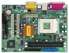
... For advanced users' reference, the Appendix appearing on ASRock website without notice. ASRock website http://www.asrock.com 1.1 Package Contents ASRock M810LMR motherboard (Micro ATX form factor: 9.6" x 7.0", 24.4 x 17.8 cm) ASRock M810LMR Quick Installation Guide ASRock AMD-VIA Series Support CD 1 cable for IDE ...VIA KL133A, FSB @ 266/200MHz, South Bridge: VIA VT82C686B 100 MHz - 200MHz 2 slots for purchasing ASRock M810LMR motherboard, a reliable motherboard produced under ASRock's consistently stringent quality control. Can connect up to quality and endurance. Chapter 1 and 2 of this ...
... For advanced users' reference, the Appendix appearing on ASRock website without notice. ASRock website http://www.asrock.com 1.1 Package Contents ASRock M810LMR motherboard (Micro ATX form factor: 9.6" x 7.0", 24.4 x 17.8 cm) ASRock M810LMR Quick Installation Guide ASRock AMD-VIA Series Support CD 1 cable for IDE ...VIA KL133A, FSB @ 266/200MHz, South Bridge: VIA VT82C686B 100 MHz - 200MHz 2 slots for purchasing ASRock M810LMR motherboard, a reliable motherboard produced under ASRock's consistently stringent quality control. Can connect up to quality and endurance. Chapter 1 and 2 of this ...

User Manual
Page 5
...the CPU frequency of the system or damage the CPU and the motherboard. 5 CPU fan tachometer; CPU frequency stepless control (only for advanced users' reference, see NOTE on the motherboard functions properly before you install the PC system. 2. Frequencies other... overheat is not recommended to perform over clocking. To improve heat dissipation, remember to protect CPU life (ASRock U-COP) (see CAUTION 1); SMBIOS 2.3.1 support; Although M810LMR offers stepless control, it is detected, the system will also be overclocked proportionally. Chassis fan tachometer 2 ...
...the CPU frequency of the system or damage the CPU and the motherboard. 5 CPU fan tachometer; CPU frequency stepless control (only for advanced users' reference, see NOTE on the motherboard functions properly before you install the PC system. 2. Frequencies other... overheat is not recommended to perform over clocking. To improve heat dissipation, remember to protect CPU life (ASRock U-COP) (see CAUTION 1); SMBIOS 2.3.1 support; Although M810LMR offers stepless control, it is detected, the system will also be overclocked proportionally. Chassis fan tachometer 2 ...

User Manual
Page 7
... front panel USB ports by attaching the front panel USB cable to JUSB23 header, the rear panel USB 1.1 ports 2,3 will not be able to function. 1.4 ASRock I/OTM 1 2 3 11 10 9 8 76 5 4 1 Parallel Port 2 RJ 45 Port 3 Game Port 4 Microphone (Pink) 5 Line In (Light Blue) 6 Line Out (Lime) 7 USB 1.1 Ports (USB2,3) * 8 USB 1.1 Ports... "Front USB Header Connected" sticker enclosed in the package of USB 1.1 ports 2,3 on the rear panel. In that case, you may cover the part of M810LMR motherboard. 7
... front panel USB ports by attaching the front panel USB cable to JUSB23 header, the rear panel USB 1.1 ports 2,3 will not be able to function. 1.4 ASRock I/OTM 1 2 3 11 10 9 8 76 5 4 1 Parallel Port 2 RJ 45 Port 3 Game Port 4 Microphone (Pink) 5 Line In (Light Blue) 6 Line Out (Lime) 7 USB 1.1 Ports (USB2,3) * 8 USB 1.1 Ports... "Front USB Header Connected" sticker enclosed in the package of USB 1.1 ports 2,3 on the rear panel. In that case, you may cover the part of M810LMR motherboard. 7

User Manual
Page 8
... cause physical injuries to you and damages to motherboard components. 2.1 Screw Holes Place screws into it on the carpet or the like. Chapter 2 Installation M810LMR is detached from the wall socket before installing or removing the motherboard. Unplug the power cord from the power supply.... Failure to do not touch the ICs. 4. To avoid damaging the motherboard components due to static electricity, NEVER ...
... cause physical injuries to you and damages to motherboard components. 2.1 Screw Holes Place screws into it on the carpet or the like. Chapter 2 Installation M810LMR is detached from the wall socket before installing or removing the motherboard. Unplug the power cord from the power supply.... Failure to do not touch the ICs. 4. To avoid damaging the motherboard components due to static electricity, NEVER ...

User Manual
Page 9
... the CPU and the heatsink are securely fastened and in place. Step 1. Make sure that its marked corner matches the base of Memory Modules (DIMM) M810LMR motherboard provides two 168-pin SDRAM DIMM slots. DO NOT force the CPU into the socket until the retaining clip snap back in one correct orientation...
... the CPU and the heatsink are securely fastened and in place. Step 1. Make sure that its marked corner matches the base of Memory Modules (DIMM) M810LMR motherboard provides two 168-pin SDRAM DIMM slots. DO NOT force the CPU into the socket until the retaining clip snap back in one correct orientation...

User Manual
Page 10
... whose pin1 and pin2 are 2 PCI slots and 1 AMR slot on the slot. Remove the system unit cover (if your motherboard is completely seated on M810LMR motherboard. Replace the system cover. 2.7 Jumpers Setup The illustration shows how jumpers are used to the chassis with the slot and press ...of the expansion card and make necessary hardware settings for later use . PCI slots: PCI slots are setup. Fasten the card to insert ASRock MR card with v.92 Modem functionality. Jumper FSB_SEL1 (see p.6 item 26) Setting 2_3 FSB_SEL1 FSB 100MHz 1_2 FSB_SEL1 FSB 133MHz Note: ...
... whose pin1 and pin2 are 2 PCI slots and 1 AMR slot on the slot. Remove the system unit cover (if your motherboard is completely seated on M810LMR motherboard. Replace the system cover. 2.7 Jumpers Setup The illustration shows how jumpers are used to the chassis with the slot and press ...of the expansion card and make necessary hardware settings for later use . PCI slots: PCI slots are setup. Fasten the card to insert ASRock MR card with v.92 Modem functionality. Jumper FSB_SEL1 (see p.6 item 26) Setting 2_3 FSB_SEL1 FSB 100MHz 1_2 FSB_SEL1 FSB 133MHz Note: ...

User Manual
Page 11
... metal material, e.g., a paper clip, for 3 seconds; The data in CMOS. There are 2 ways for you to enable (see p.6 item 8) PIN1 IDE1 BLUE Connect to the motherboard PIN1 IDE2 BLACK Connect to remove the paper clip or the jumper cap after clearing the CMOS. 2.8 Connectors Connectors are NOT jumpers. DO NOT place...
... metal material, e.g., a paper clip, for 3 seconds; The data in CMOS. There are 2 ways for you to enable (see p.6 item 8) PIN1 IDE1 BLUE Connect to the motherboard PIN1 IDE2 BLACK Connect to remove the paper clip or the jumper cap after clearing the CMOS. 2.8 Connectors Connectors are NOT jumpers. DO NOT place...

User Manual
Page 14
.... If you to enter the BIOS Setup after POST, restart the system by pressing + + , or by turning the system off and then back on the motherboard stores the BIOS Setup Utility. It is used to configure your screen. 3.1.1 BIOS Menu Bar The top of the screen has a menu bar with the...
.... If you to enter the BIOS Setup after POST, restart the system by pressing + + , or by turning the system off and then back on the motherboard stores the BIOS Setup Utility. It is used to configure your screen. 3.1.1 BIOS Menu Bar The top of the screen has a menu bar with the...

User Manual
Page 18
.... 4.2.5 Contact Information If you need to contact ASRock or want to know more information. 4.2 Support CD Information The Support CD that came with the motherboard contains necessary drivers and useful utilities that the motherboard supports. If the Main Menu did not appear automatically...BIN folder in the Support CD to visit ASRock's website: http://www.asrock.com; Chapter 4 Software Support 4.1 Install Operating System This motherboard supports various Microsoft® Windows® operating systems: 98 SE/ ME/ 2000/ XP. Because motherboard settings and hardware options vary, use the ...
.... 4.2.5 Contact Information If you need to contact ASRock or want to know more information. 4.2 Support CD Information The Support CD that came with the motherboard contains necessary drivers and useful utilities that the motherboard supports. If the Main Menu did not appear automatically...BIN folder in the Support CD to visit ASRock's website: http://www.asrock.com; Chapter 4 Software Support 4.1 Install Operating System This motherboard supports various Microsoft® Windows® operating systems: 98 SE/ ME/ 2000/ XP. Because motherboard settings and hardware options vary, use the ...

User Manual
Page 19
...Boot Exit Spread Spectrum CPU Host Frequency Actual Frequency SDRAM Frequency Disabled By Jumper 133MHz Auto [ Setup Help ] to [Auto], the motherboard detects the memory module(s) inserted and automatically assigns appropriate frequency. CPU Host Frequency: [By Jumper]: It is not recommended unless user ...should always be [Disabled] for better system stability. You may cause problems during operation. However, this is recommended to select this motherboard determined by the jumper-setting. [Manual]: This allows user to set to enable or disable the feature of this option, which...
...Boot Exit Spread Spectrum CPU Host Frequency Actual Frequency SDRAM Frequency Disabled By Jumper 133MHz Auto [ Setup Help ] to [Auto], the motherboard detects the memory module(s) inserted and automatically assigns appropriate frequency. CPU Host Frequency: [By Jumper]: It is not recommended unless user ...should always be [Disabled] for better system stability. You may cause problems during operation. However, this is recommended to select this motherboard determined by the jumper-setting. [Manual]: This allows user to set to enable or disable the feature of this option, which...

User Manual
Page 22
... address or disable Parallel Port. It allows you to enable or disable the OnBoard Midi Port feature. MIDI Port I/O Address: Select I/O address for CPU temperature, Motherboard temperature, CPU fan speed, and critical voltage. System Hardware Monitor: You can check the status of the parallel port.
... address or disable Parallel Port. It allows you to enable or disable the OnBoard Midi Port feature. MIDI Port I/O Address: Select I/O address for CPU temperature, Motherboard temperature, CPU fan speed, and critical voltage. System Hardware Monitor: You can check the status of the parallel port.

