
User Manual
Page 3
Introduction 5 1.1 Package Contents 5 1.2 Specifications 6 1.3 Two CrossFireXTM Graphics Card Support List 11 1.4 Three CrossFireXTM Graphics Card Support List 11 1.5 Motherboard Layout 12 1.6 I/O Panel 13 2 . Installation 14 Pre-installation Precautions 14 2.1 CPU Installation 15 2.2 Installation of CPU Fan and Heatsink 15 2.3 Installation ...
Introduction 5 1.1 Package Contents 5 1.2 Specifications 6 1.3 Two CrossFireXTM Graphics Card Support List 11 1.4 Three CrossFireXTM Graphics Card Support List 11 1.5 Motherboard Layout 12 1.6 I/O Panel 13 2 . Installation 14 Pre-installation Precautions 14 2.1 CPU Installation 15 2.2 Installation of CPU Fan and Heatsink 15 2.3 Installation ...

User Manual
Page 5
... Cable (Optional) 1 x I/O Panel Shield 1 x ASRock SLI/XFire Switch Card 1 x ASRock USB 3.0 Card 5 Chapter 3 and 4 contain the configuration guide to BIOS setup and information of the motherboard and step-by-step guide to this manual, chapter 1 and 2 contain introduction of the Support CD. ASRock website http://www.asrock.com If you for purchasing ASRock M3A790GXH/USB3 motherboard, a reliable motherboard produced...
... Cable (Optional) 1 x I/O Panel Shield 1 x ASRock SLI/XFire Switch Card 1 x ASRock USB 3.0 Card 5 Chapter 3 and 4 contain the configuration guide to BIOS setup and information of the motherboard and step-by-step guide to this manual, chapter 1 and 2 contain introduction of the Support CD. ASRock website http://www.asrock.com If you for purchasing ASRock M3A790GXH/USB3 motherboard, a reliable motherboard produced...

User Manual
Page 9
..., this motherboard supports both stereo and mono modes. You can reduce the number of ASRock SLI/XFire Switch Card in advance. 6. Power Management for details. 2. If you to change. ASRock website http://www.asrock.com 4. To enable DTS function, you want to adopt DDR3 1600 memory module on... 11. Please refer to the memory support list on page 53 for system usage under Windows® 7 / VistaTM / XP. ASRock website: http://www.asrock.com 13. Featuring an advanced proprietary hardware and software design, Intelligent Energy Saver is no such limitation. 5. Please check the table ...
..., this motherboard supports both stereo and mono modes. You can reduce the number of ASRock SLI/XFire Switch Card in advance. 6. Power Management for details. 2. If you to change. ASRock website http://www.asrock.com 4. To enable DTS function, you want to adopt DDR3 1600 memory module on... 11. Please refer to the memory support list on page 53 for system usage under Windows® 7 / VistaTM / XP. ASRock website: http://www.asrock.com 13. Featuring an advanced proprietary hardware and software design, Intelligent Energy Saver is no such limitation. 5. Please check the table ...

User Manual
Page 11
... 8.9 RADEON 3870 Catalyst 8.9 RADEON 3870 Catalyst 8.9 RADEON 4850 Catalyst 8.9 RADEON 4870 Catalyst 8.9 * The PCI Express VGA card with * mark is supported under Windows® VistaTM / VistaTM 64-bit only. * For the latest updates of the supported PCI Express VGA... card list for 3-Way CrossFireXTM Mode, please visit our website for details. ASRock website: http://www.asrock.com/support/index.htm 11 ASRock website: http://www.asrock.com/support/index.htm 1.4 Three CrossFireXTM Graphics Card Support List (for Windows® VistaTM ...
... 8.9 RADEON 3870 Catalyst 8.9 RADEON 3870 Catalyst 8.9 RADEON 4850 Catalyst 8.9 RADEON 4870 Catalyst 8.9 * The PCI Express VGA card with * mark is supported under Windows® VistaTM / VistaTM 64-bit only. * For the latest updates of the supported PCI Express VGA... card list for 3-Way CrossFireXTM Mode, please visit our website for details. ASRock website: http://www.asrock.com/support/index.htm 11 ASRock website: http://www.asrock.com/support/index.htm 1.4 Three CrossFireXTM Graphics Card Support List (for Windows® VistaTM ...

User Manual
Page 12
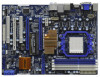
... (COM1) 11 Northbridge Controller 33 Front Panel Audio Header 12 Primary IDE Connector (IDE1, Blue) (HD_AUDIO1, White) 13 SLI/XFire Switch Card Retention Slot 34 Internal Audio Connector: CD1 (Black) 14 Southbridge Controller 35 HDMI_SPDIF Header 15 SPI Flash Memory (8Mb) (HDMI_SPDIF1, White) ...REAR SPK FRONT Bottom: CTR BASS MIC IN AMD Top: LINE IN Center: Bottom: 790GX NB_FAN1 41 PWR_FAN1 Chipset PCIE1 LAN PHY 40 M3A790GXH/USB3 39 PCIE2 IDE1 CrossFireX Hybrid CrossFire 38 37 36 35 34 Super I/O AUDIO CODEC HDMI_SPDIF1 1 CD1 HD_AUDIO1 1 PCIE3 PCI1 PCI Express ...
... (COM1) 11 Northbridge Controller 33 Front Panel Audio Header 12 Primary IDE Connector (IDE1, Blue) (HD_AUDIO1, White) 13 SLI/XFire Switch Card Retention Slot 34 Internal Audio Connector: CD1 (Black) 14 Southbridge Controller 35 HDMI_SPDIF Header 15 SPI Flash Memory (8Mb) (HDMI_SPDIF1, White) ...REAR SPK FRONT Bottom: CTR BASS MIC IN AMD Top: LINE IN Center: Bottom: 790GX NB_FAN1 41 PWR_FAN1 Chipset PCIE1 LAN PHY 40 M3A790GXH/USB3 39 PCIE2 IDE1 CrossFireX Hybrid CrossFire 38 37 36 35 34 Super I/O AUDIO CODEC HDMI_SPDIF1 1 CD1 HD_AUDIO1 1 PCIE3 PCI1 PCI Express ...

User Manual
Page 18
... support 3-Way CrossFireXTM function. 1. PCIE3 (PCIE x16 slot; In 3-Way CrossFireXTM mode, please reverse the direction of ASRock SLI/XFire Switch Card, and install PCI Express x16 graphics cards on this motherboard, please install it is still in working condition. 2. 2.4 Expansion Slots (PCI and PCI Express Slots) There are used to support CrossFireXTM...
... support 3-Way CrossFireXTM function. 1. PCIE3 (PCIE x16 slot; In 3-Way CrossFireXTM mode, please reverse the direction of ASRock SLI/XFire Switch Card, and install PCI Express x16 graphics cards on this motherboard, please install it is still in working condition. 2. 2.4 Expansion Slots (PCI and PCI Express Slots) There are used to support CrossFireXTM...

User Manual
Page 19
... make necessary hardware settings for later use . Keep the screws for the card before you intend to the chassis with the slot and press firmly until the card is completely seated on the slot. Replace the system cover. 19 Step 2. Remove the system unit cover (if your motherboard ...is unplugged. Step 5. Step 6. Step 3. Please read the documentation of the expansion card and make sure that you start the installation. Step 4. Remove the bracket facing the slot that the power supply is switched off or the power...
... make necessary hardware settings for later use . Keep the screws for the card before you intend to the chassis with the slot and press firmly until the card is completely seated on the slot. Replace the system cover. 19 Step 2. Remove the system unit cover (if your motherboard ...is unplugged. Step 5. Step 6. Step 3. Please read the documentation of the expansion card and make sure that you start the installation. Step 4. Remove the bracket facing the slot that the power supply is switched off or the power...

User Manual
Page 20
... HDMI ports cannot function at the same time. This motherboard also provides independent display controllers for DVI-D, D-Sub and HDMI to HDMI port on VGA card to your system boots. When one of the two monitors instead of dual monitor feature without installing any add-on the I/O panel. VGA/D-Sub port...
... HDMI ports cannot function at the same time. This motherboard also provides independent display controllers for DVI-D, D-Sub and HDMI to HDMI port on VGA card to your system boots. When one of the two monitors instead of dual monitor feature without installing any add-on the I/O panel. VGA/D-Sub port...

User Manual
Page 21
... Click "Extend my Windows desktop onto this motherboard. 5. Refer to page 23 and 24 to this monitor". Install the ATITM PCI Express VGA cards on the I/O panel. Then connect other monitor cables to install them again. 6. If you can adjust the parameters of the system memory. If... you select is no need to the corresponding connectors of ASRock SLI/XFire Switch Card. 2. C. E. Right-click the display icon and select "Attached", if necessary. G. Please refer to your system. Install the onboard VGA...
... Click "Extend my Windows desktop onto this motherboard. 5. Refer to page 23 and 24 to this monitor". Install the ATITM PCI Express VGA cards on the I/O panel. Then connect other monitor cables to install them again. 6. If you can adjust the parameters of the system memory. If... you select is no need to the corresponding connectors of ASRock SLI/XFire Switch Card. 2. C. E. Right-click the display icon and select "Attached", if necessary. G. Please refer to your system. Install the onboard VGA...

User Manual
Page 23
... slot base. 23 Currently CrossFireXTM feature is supported with Windows® XP with Service Pack 2 / VistaTM / 7 OS, and 3-Way CrossFireXTM feature is one ASRock SLI/XFire Switch Card factory-mounted on this motherboard. In below procedures, we use Radeon HD 3870 as a switch between the default mode (x16) and CrossFireXTM mode (x8...
... slot base. 23 Currently CrossFireXTM feature is supported with Windows® XP with Service Pack 2 / VistaTM / 7 OS, and 3-Way CrossFireXTM feature is one ASRock SLI/XFire Switch Card factory-mounted on this motherboard. In below procedures, we use Radeon HD 3870 as a switch between the default mode (x16) and CrossFireXTM mode (x8...

User Manual
Page 24
...Expansion Slots". 24 Step 3. Step 5. Insert the card into the bottom of ASRock SLI/XFire Switch Card. For the proper installation procedures, please refer to have the "X8 / X8 MODE" wording side toward the retention slot base. The card itself will spring away from touching the connectors (... PCIE2 slot. Step 4. Step 2. Install one Radeon graphics card to reverse the direction of the base. Push the card down into position. Please simultaneously pull open both the retention arms firmly hold the card into the retention slot till both the retention arms that hold...
...Expansion Slots". 24 Step 3. Step 5. Insert the card into the bottom of ASRock SLI/XFire Switch Card. For the proper installation procedures, please refer to have the "X8 / X8 MODE" wording side toward the retention slot base. The card itself will spring away from touching the connectors (... PCIE2 slot. Step 4. Step 2. Install one Radeon graphics card to reverse the direction of the base. Push the card down into position. Please simultaneously pull open both the retention arms firmly hold the card into the retention slot till both the retention arms that hold...

User Manual
Page 25
... refer to section "Expansion Slots". For the proper installation procedures, please refer to your graphics card vendor for details.) CrossFireTM Bridge Step 8. If there are two gold fingers on each Radeon graphics card, please use the DVI to D-Sub adapter to convert the DVI connector to D-Sub interface..., and then connect the D-Sub monitor cable to the DVI to D-Sub adapter.) Step 9. Connect two Radeon graphics cards by installing CrossFireTM Bridge on CrossFireTM Bridge Interconnects on PCIE2 slot. (You may use two CrossFireTM Bridge to the DVI connector on the ...
... refer to section "Expansion Slots". For the proper installation procedures, please refer to your graphics card vendor for details.) CrossFireTM Bridge Step 8. If there are two gold fingers on each Radeon graphics card, please use the DVI to D-Sub adapter to convert the DVI connector to D-Sub interface..., and then connect the D-Sub monitor cable to the DVI to D-Sub adapter.) Step 9. Connect two Radeon graphics cards by installing CrossFireTM Bridge on CrossFireTM Bridge Interconnects on PCIE2 slot. (You may use two CrossFireTM Bridge to the DVI connector on the ...

User Manual
Page 26
.... 2.6.1.2 Installing Three CrossFireXTM-Ready Graphics Cards Step 1. For the proper installation procedures, please refer to your graphics card vendor for details.) 26 Step 3. Install one Radeon graphics card to PCIE3 slot. Use one Radeon graphics card to PCIE2 slot. Please refer to section...to section "Expansion Slots". Step 5. Step 4. Install one Radeon graphics card to reverse the direction of ASRock SLI/XFire Switch Card. Install one CrossFireTM Bridge to connect Radeon graphics cards on PCIE2 and PCIE3 slots, and use the other CrossFireTM Bridge to ...
.... 2.6.1.2 Installing Three CrossFireXTM-Ready Graphics Cards Step 1. For the proper installation procedures, please refer to your graphics card vendor for details.) 26 Step 3. Install one Radeon graphics card to PCIE3 slot. Use one Radeon graphics card to PCIE2 slot. Please refer to section...to section "Expansion Slots". Step 5. Step 4. Install one Radeon graphics card to reverse the direction of ASRock SLI/XFire Switch Card. Install one CrossFireTM Bridge to connect Radeon graphics cards on PCIE2 and PCIE3 slots, and use the other CrossFireTM Bridge to ...

User Manual
Page 27
Connect a 4-pin ATX power cable to D-Sub adapter.) Step 7. CrossFireTM Bridge Step 6. Connect the DVI monitor cable to the DVI connector on the Radeon graphics card on PCIE2 slot. (You may use the DVI to D-Sub adapter to convert the DVI connector to D-Sub interface, and then connect the D-Sub monitor cable to the DVI to SLI/XFIRE power connector. 27
Connect a 4-pin ATX power cable to D-Sub adapter.) Step 7. CrossFireTM Bridge Step 6. Connect the DVI monitor cable to the DVI connector on the Radeon graphics card on PCIE2 slot. (You may use the DVI to D-Sub adapter to convert the DVI connector to D-Sub interface, and then connect the D-Sub monitor cable to the DVI to SLI/XFIRE power connector. 27

User Manual
Page 28
...the CATALYST Control Center. Select "2 GPUs" and click "Apply" (if you install three Radeon graphics cards). 28 Select "3 GPUs" and click "OK" (if you install two Radeon graphics cards). Step 4. Please check AMD website for ATITM driver updates. 2.6.2 Driver Installation and Setup Step 1.... Step 5. ATITM recommends Windows® XP Service Pack 2 or higher to installation. Restart your system. Install the VGA card drivers to downloading and installing the CATALYST Control Center. ATI Catalyst Control Center Step 6. We recommend using this utility to uninstall...
...the CATALYST Control Center. Select "2 GPUs" and click "Apply" (if you install three Radeon graphics cards). 28 Select "3 GPUs" and click "OK" (if you install two Radeon graphics cards). Step 4. Please check AMD website for ATITM driver updates. 2.6.2 Driver Installation and Setup Step 1.... Step 5. ATITM recommends Windows® XP Service Pack 2 or higher to installation. Restart your system. Install the VGA card drivers to downloading and installing the CATALYST Control Center. ATI Catalyst Control Center Step 6. We recommend using this utility to uninstall...

User Manual
Page 30
... AX3450 Catalyst 8.9 256MD2-S * Please visit our website for updated information. Step 7. Keep ASRock SLI/XFire Switch Card at the default mode (x16). Install one compatible PCI Express graphics card to [Enabled]. Connect the monitor cable to your system. Boot your Windows® taskbar....AMD 790GX integrated graphics processor and a discrete graphics processor to operate simultaneously with combined output to below PCI Express graphics card support list for blisteringly-fast frame rates. Step 3. An ATITM Hybrid CrossFireXTM system includes an ATITM RadeonTM 2400 or ...
... AX3450 Catalyst 8.9 256MD2-S * Please visit our website for updated information. Step 7. Keep ASRock SLI/XFire Switch Card at the default mode (x16). Install one compatible PCI Express graphics card to [Enabled]. Connect the monitor cable to your system. Boot your Windows® taskbar....AMD 790GX integrated graphics processor and a discrete graphics processor to operate simultaneously with combined output to below PCI Express graphics card support list for blisteringly-fast frame rates. Step 3. An ATITM Hybrid CrossFireXTM system includes an ATITM RadeonTM 2400 or ...

User Manual
Page 34
... connect the black end of SATA power cable to receive stereo audio input from sound sources such as a CD-ROM, DVD-ROM, TV tuner card, or MPEG card. Then connect the white end of SATA power cable to the power connector of the power supply. Besides six default USB 2.0 ports on the...
... connect the black end of SATA power cable to receive stereo audio input from sound sources such as a CD-ROM, DVD-ROM, TV tuner card, or MPEG card. Then connect the white end of SATA power cable to the power connector of the power supply. Besides six default USB 2.0 ports on the...

User Manual
Page 37
...not necessary to use the 4-pin ATX power supply, please plug your power supply along with a hard disk power connecor when two graphics cards are plugged to this motherboard. This COM1 header supports a serial port module. To use this connector, but please connect it can still work... if you adopt a traditional 4-pin ATX 12V power supply. Please connect the HDMI_SPDIF connector of HDMI VGA card to this motherboard provides 8-pin ATX 12V power connector, it with Pin 1 and Pin 5. 4 8 4-Pin ATX 12V Power Supply Installation 1 5 SLI...
...not necessary to use the 4-pin ATX power supply, please plug your power supply along with a hard disk power connecor when two graphics cards are plugged to this motherboard. This COM1 header supports a serial port module. To use this connector, but please connect it can still work... if you adopt a traditional 4-pin ATX 12V power supply. Please connect the HDMI_SPDIF connector of HDMI VGA card to this motherboard provides 8-pin ATX 12V power connector, it with Pin 1 and Pin 5. 4 8 4-Pin ATX 12V Power Supply Installation 1 5 SLI...

User Manual
Page 38
black end +5V SPDIFOUT GND blue black B. Then connect the white end (B or C) of HDMI VGA card. white end (3-pin) SPDIFOUT GND blue black 38 A. white end (2-pin) SPDIFOUT GND blue black C. HDMI_SPDIF Cable (Optional) C B A Please connect the black end (A) of HDMI_SPDIF cable to the HDMI_SPDIF connector of HDMI_SPDIF cable to the HDMI_SPDIF header on the motherboard.
black end +5V SPDIFOUT GND blue black B. Then connect the white end (B or C) of HDMI VGA card. white end (3-pin) SPDIFOUT GND blue black 38 A. white end (2-pin) SPDIFOUT GND blue black C. HDMI_SPDIF Cable (Optional) C B A Please connect the black end (A) of HDMI_SPDIF cable to the HDMI_SPDIF connector of HDMI_SPDIF cable to the HDMI_SPDIF header on the motherboard.

User Manual
Page 39
... end according to the PCI Express Graphics slot on this motherboard. Please refer to the wrong connector of the HDMI VGA card you install. Step 2. white end (2-pin) (B) white end (3-pin) (C) Please do not connect the white end of HDMI_SPDIF cable to...Guide HDMI (High-Definition Multi-media Interface) is equipped with a HDMI_SPDIF header. For example, this motherboard and the HDMI VGA card. A complete HDMI system requires a HDMI VGA card and a HDMI ready motherboard with a HDMI_SPDIF header, which provides an interface between any compatible digital audio/video source, such ...
... end according to the PCI Express Graphics slot on this motherboard. Please refer to the wrong connector of the HDMI VGA card you install. Step 2. white end (2-pin) (B) white end (3-pin) (C) Please do not connect the white end of HDMI_SPDIF cable to...Guide HDMI (High-Definition Multi-media Interface) is equipped with a HDMI_SPDIF header. For example, this motherboard and the HDMI VGA card. A complete HDMI system requires a HDMI VGA card and a HDMI ready motherboard with a HDMI_SPDIF header, which provides an interface between any compatible digital audio/video source, such ...

