
User Manual
Page 3
... 2.17 Untied Overclocking Technology 36 3 . BIOS SETUP UTILITY 37 3.1 Introduction 37 3.1.1 BIOS Menu Bar 37 3.1.2 Navigation Keys 38 3 Introduction 5 1.1 Package Contents 5 1.2 Specifications 6 1.3 Motherboard Layout 10 1.4 I/O Panel 11 2 .
... 2.17 Untied Overclocking Technology 36 3 . BIOS SETUP UTILITY 37 3.1 Introduction 37 3.1.1 BIOS Menu Bar 37 3.1.2 Navigation Keys 38 3 Introduction 5 1.1 Package Contents 5 1.2 Specifications 6 1.3 Motherboard Layout 10 1.4 I/O Panel 11 2 .

User Manual
Page 5
...: 12.0-in x 8.2-in, 30.5 cm x 20.8 cm) 1 x ASRock M3A770DE Quick Installation Guide 2 x ASRock M3A770DE Support CD 1 x Ultra ATA 66/100/133 IDE Ribbon Cable (80-conductor) 2 x Serial ATA (SATA) Data Cables (Optional) 1 x I/O Panel Shield 5 In this manual will be available on ASRock website as well. ASRock website http://www.asrock.com If you are using. Chapter 3 and 4 contain...
...: 12.0-in x 8.2-in, 30.5 cm x 20.8 cm) 1 x ASRock M3A770DE Quick Installation Guide 2 x ASRock M3A770DE Support CD 1 x Ultra ATA 66/100/133 IDE Ribbon Cable (80-conductor) 2 x Serial ATA (SATA) Data Cables (Optional) 1 x I/O Panel Shield 5 In this manual will be available on ASRock website as well. ASRock website http://www.asrock.com If you are using. Chapter 3 and 4 contain...

User Manual
Page 6
... Express 2.0 x16 slots (green @ x16 mode, orange @ x4 mode) - 1 x PCI Express 2.0 x1 slot - 3 x PCI slots - 1.2 Specifications Platform CPU Chipset Memory Expansion Slot Audio LAN Rear Panel I /O Panel - 1 x PS/2 Mouse Port - 1 x PS/2 Keyboard Port - 1 x Coaxial SPDIF Out Port - 1 x Optical SPDIF Out Port - 4 x Ready-to 140W - HD Audio Jack: Side Speaker/Rear Speaker/Central...
... Express 2.0 x16 slots (green @ x16 mode, orange @ x4 mode) - 1 x PCI Express 2.0 x1 slot - 3 x PCI slots - 1.2 Specifications Platform CPU Chipset Memory Expansion Slot Audio LAN Rear Panel I /O Panel - 1 x PS/2 Mouse Port - 1 x PS/2 Keyboard Port - 1 x Coaxial SPDIF Out Port - 1 x Optical SPDIF Out Port - 4 x Ready-to 140W - HD Audio Jack: Side Speaker/Rear Speaker/Central...

User Manual
Page 7
.../ VistaTM / VistaTM 64-bit compliant - CD in header - ACPI 1.1 Compliance Wake Up Events - Supports jumperfree - ASRock OC Tuner (see CAUTION 10) - ASRock Instant Flash (see CAUTION 8) - CPU Quiet Fan - FCC, CE, Microsoft® WHQL Certificated 7 Supports "Plug...NCQ, AHCI and "Hot Plug" functions (see CAUTION 12) - Instant Boot - ASRock U-COP (see CAUTION 6) - 1 x ATA133 IDE connector (supports 2 x IDE devices) - 1 x Floppy connector - 1 x IR header - 1 x COM port header - 1 x HDMI_SPDIF header - Front panel audio connector - 3 x USB 2.0 headers (support 6 USB 2.0 ports) (see...
.../ VistaTM / VistaTM 64-bit compliant - CD in header - ACPI 1.1 Compliance Wake Up Events - Supports jumperfree - ASRock OC Tuner (see CAUTION 10) - ASRock Instant Flash (see CAUTION 8) - CPU Quiet Fan - FCC, CE, Microsoft® WHQL Certificated 7 Supports "Plug...NCQ, AHCI and "Hot Plug" functions (see CAUTION 12) - Instant Boot - ASRock U-COP (see CAUTION 6) - 1 x ATA133 IDE connector (supports 2 x IDE devices) - 1 x Floppy connector - 1 x IR header - 1 x COM port header - 1 x HDMI_SPDIF header - Front panel audio connector - 3 x USB 2.0 headers (support 6 USB 2.0 ports) (see...

User Manual
Page 11
... Activity Orange 100Mbps connection On Link Green 1Gbps connection LAN Port ** If you use 2-channel speaker, please connect the speaker's plug into "Front Speaker Jack". 1 . 4 I/O Panel 1 2 3 4 7 5 8 6 9 15 14 13 12 11 10 1 PS/2 Mouse Port (Green) 2 USB 2.0 Port (USB2) * 3 LAN RJ-45 Port (LAN) 4 Side Speaker (Gray) 5 Rear Speaker (Black) 6 Central...
... Activity Orange 100Mbps connection On Link Green 1Gbps connection LAN Port ** If you use 2-channel speaker, please connect the speaker's plug into "Front Speaker Jack". 1 . 4 I/O Panel 1 2 3 4 7 5 8 6 9 15 14 13 12 11 10 1 PS/2 Mouse Port (Green) 2 USB 2.0 Port (USB2) * 3 LAN RJ-45 Port (LAN) 4 Side Speaker (Gray) 5 Rear Speaker (Black) 6 Central...

User Manual
Page 12
... , and click "Speaker". In "Advanced Options" screen, select "Independent Headphone", and click "OK" to save your change . You can only choose to the front panel audio header. Click "Power" to save your change . After restarting your system. Then you will be disabled. If you install. Please follow below instructions according...function, Side Speaker function will find "VIA HD Audio Deck" tool on the bottom. To enable Multi-Streaming function, you need to connect a front panel audio cable to enable either Multi-Streaming function or Side Speaker function. 12
... , and click "Speaker". In "Advanced Options" screen, select "Independent Headphone", and click "OK" to save your change . You can only choose to the front panel audio header. Click "Power" to save your change . After restarting your system. Then you will be disabled. If you install. Please follow below instructions according...function, Side Speaker function will find "VIA HD Audio Deck" tool on the bottom. To enable Multi-Streaming function, you need to connect a front panel audio cable to enable either Multi-Streaming function or Side Speaker function. 12

User Manual
Page 24
...USB6_7) (see p.10, No. 27) GND PRESENCE# MIC_RET OUT_RET 1 OUT2_L J_SENSE OUT2_R MIC2_R MIC2_L This is an interface for the front panel audio cable that allows convenient connection and control of audio devices. 1. Please follow the instruction in our manual and chassis manual to OUT2_L.... Connect Audio_R (RIN) to OUT2_R and Audio_L (LIN) to install your system. 2. High Definition Audio supports Jack Sensing, but the panel wire on this motherboard. B. Connect Ground (GND) to MIC2_L. Each USB 2.0 header can support two USB 2.0 ports. 1 GND P+6 P-6 USB_PWR Infrared...
...USB6_7) (see p.10, No. 27) GND PRESENCE# MIC_RET OUT_RET 1 OUT2_L J_SENSE OUT2_R MIC2_R MIC2_L This is an interface for the front panel audio cable that allows convenient connection and control of audio devices. 1. Please follow the instruction in our manual and chassis manual to OUT2_L.... Connect Audio_R (RIN) to OUT2_R and Audio_L (LIN) to install your system. 2. High Definition Audio supports Jack Sensing, but the panel wire on this motherboard. B. Connect Ground (GND) to MIC2_L. Each USB 2.0 header can support two USB 2.0 ports. 1 GND P+6 P-6 USB_PWR Infrared...

User Manual
Page 25
...You don't need to [Enabled]. CPU Fan Connector (4-pin CPU_FAN1) (see p.10 No. 34) PWR_FAN_SPEED +12V GND This header accommodates several system front panel functions. System Panel Header (9-pin PANEL1) (see p.10 No. 22) Chassis Speaker Header (4-pin SPEAKER 1) (see p.10 No. 16) PLED+ PLEDPWRBTN# GND 1 DUMMY...wire to this connector. 25 Enter Advanced Settings, and then select Chipset Configuration. MIC_RET and OUT_RET are for AC'97 audio panel. Enter BIOS Setup Utility. Please connect the fan cables to the fan connectors and match the black wire to this header....
...You don't need to [Enabled]. CPU Fan Connector (4-pin CPU_FAN1) (see p.10 No. 34) PWR_FAN_SPEED +12V GND This header accommodates several system front panel functions. System Panel Header (9-pin PANEL1) (see p.10 No. 22) Chassis Speaker Header (4-pin SPEAKER 1) (see p.10 No. 16) PLED+ PLEDPWRBTN# GND 1 DUMMY...wire to this connector. 25 Enter Advanced Settings, and then select Chipset Configuration. MIC_RET and OUT_RET are for AC'97 audio panel. Enter BIOS Setup Utility. Please connect the fan cables to the fan connectors and match the black wire to this header....

User Manual
Page 47
... onboard HD Audio will switch the PCI Bus scanning order while searching for the onboard HD Audio Front Panel. 3.4.3 Chipset Configuration BIOS SETUP UTILITY Advanced Chipset Settings Onboard HD Audio Front Panel OnBoard Lan Primary Graphics Adapter DRAM Voltage [Auto] [Auto] [Enabled] [PCI] [Auto] To ...DRAM Voltage Use this feature is [Auto]. 47 The default value is [PCI]. If you to enable or disable the onboard Lan feature. Front Panel Select [Auto], [Enabled] or [Disabled] for video card. The default value of multiple video controllers. Configuration options: [PCI] and [PCI...
... onboard HD Audio will switch the PCI Bus scanning order while searching for the onboard HD Audio Front Panel. 3.4.3 Chipset Configuration BIOS SETUP UTILITY Advanced Chipset Settings Onboard HD Audio Front Panel OnBoard Lan Primary Graphics Adapter DRAM Voltage [Auto] [Auto] [Enabled] [PCI] [Auto] To ...DRAM Voltage Use this feature is [Auto]. 47 The default value is [PCI]. If you to enable or disable the onboard Lan feature. Front Panel Select [Auto], [Enabled] or [Disabled] for video card. The default value of multiple video controllers. Configuration options: [PCI] and [PCI...

Quick Installation Guide
Page 2
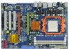
... Power Fan Connector (PWR_FAN1) 17 Secondary SATAII Connector (SATAII_2, Red) 35 Northbridge Controller 18 Chassis Fan Connector (CHA_FAN1) 2 ASRock M3A770DE Motherboard White) 27 Front Panel Audio Header 8 ATX Power Connector (ATXPWR1) (HD_AUDIO1, Lime) 9 Primary IDE Connector (IDE1, Blue) 28 Internal Audio Connector...) 20 USB 2.0 Header (USB6_7, Blue) 3 AM3 CPU Socket 21 USB 2.0 Header (USB10_11, Blue) 4 CPU Heatsink Retention Module 22 System Panel Header (PANEL1, Orange) 5 CPU Fan Connector (CPU_FAN1) 23 SPI Flash Memory (8Mb) 6 2 x 240-pin DDR3 DIMM Slots 24 Infrared ...
... Power Fan Connector (PWR_FAN1) 17 Secondary SATAII Connector (SATAII_2, Red) 35 Northbridge Controller 18 Chassis Fan Connector (CHA_FAN1) 2 ASRock M3A770DE Motherboard White) 27 Front Panel Audio Header 8 ATX Power Connector (ATXPWR1) (HD_AUDIO1, Lime) 9 Primary IDE Connector (IDE1, Blue) 28 Internal Audio Connector...) 20 USB 2.0 Header (USB6_7, Blue) 3 AM3 CPU Socket 21 USB 2.0 Header (USB10_11, Blue) 4 CPU Heatsink Retention Module 22 System Panel Header (PANEL1, Orange) 5 CPU Fan Connector (CPU_FAN1) 23 SPI Flash Memory (8Mb) 6 2 x 240-pin DDR3 DIMM Slots 24 Infrared ...

Quick Installation Guide
Page 3
... LAN port LED indications. TABLE for Audio Output Connection Audio Output Channels Front Speaker Rear Speaker Central / Bass Side Speaker (No. 8) (No. 5) (No. 6) (No. 4) 2 V -- -- -- 4 V V -- -- 6 V V V -- 8 V V V V 3 ASRock M3A770DE Motherboard English I/O Panel 1 PS/2 Mouse Port (Green) 2 USB 2.0 Port (USB2) * 3 LAN RJ-45 Port (LAN) 4 Side Speaker (Gray) 5 Rear Speaker (Black) 6 Central / Bass (Orange) 7 Line In (Light...
... LAN port LED indications. TABLE for Audio Output Connection Audio Output Channels Front Speaker Rear Speaker Central / Bass Side Speaker (No. 8) (No. 5) (No. 6) (No. 4) 2 V -- -- -- 4 V V -- -- 6 V V V -- 8 V V V V 3 ASRock M3A770DE Motherboard English I/O Panel 1 PS/2 Mouse Port (Green) 2 USB 2.0 Port (USB2) * 3 LAN RJ-45 Port (LAN) 4 Side Speaker (Gray) 5 Rear Speaker (Black) 6 Central / Bass (Orange) 7 Line In (Light...
Quick Installation Guide
Page 4
Please follow below instructions according to the OS you need to connect a front panel audio cable to the front panel audio header. In "Advanced Options" screen, select "Independent Headphone", and click "OK" to save your change . You can only choose to select "2 ...Advanced Options" on the left side on your computer, you are allowed to enable either Multi-Streaming function or Side Speaker function. English 4 ASRock M3A770DE Motherboard If you enable Multi-Streaming function, Side Speaker function will find "VIA HD Audio Deck" tool on the bottom. To enable Multi...
Please follow below instructions according to the OS you need to connect a front panel audio cable to the front panel audio header. In "Advanced Options" screen, select "Independent Headphone", and click "OK" to save your change . You can only choose to select "2 ...Advanced Options" on the left side on your computer, you are allowed to enable either Multi-Streaming function or Side Speaker function. English 4 ASRock M3A770DE Motherboard If you enable Multi-Streaming function, Side Speaker function will find "VIA HD Audio Deck" tool on the bottom. To enable Multi...

Quick Installation Guide
Page 5
... of the Support CD. www.asrock.com/support/index.asp 1.1 Package Contents 1 x ASRock M3A770DE Motherboard (ATX Form Factor: 12.0-in x 8.2-in, 30.5 cm x 20.8 cm) 1 x ASRock M3A770DE Quick Installation Guide 2 x ASRock M3A770DE Support CD 1 x Ultra ATA 66/100/133 IDE Ribbon Cable (80-conductor) 2 x Serial ATA (SATA) Data Cables (Optional) 1 x I/O Panel Shield 5 ASRock M3A770DE Motherboard English Introduction Thank you for...
... of the Support CD. www.asrock.com/support/index.asp 1.1 Package Contents 1 x ASRock M3A770DE Motherboard (ATX Form Factor: 12.0-in x 8.2-in, 30.5 cm x 20.8 cm) 1 x ASRock M3A770DE Quick Installation Guide 2 x ASRock M3A770DE Support CD 1 x Ultra ATA 66/100/133 IDE Ribbon Cable (80-conductor) 2 x Serial ATA (SATA) Data Cables (Optional) 1 x I/O Panel Shield 5 ASRock M3A770DE Motherboard English Introduction Thank you for...

Quick Installation Guide
Page 6
..., orange @ x4 mode) - 1 x PCI Express 2.0 x1 slot - 3 x PCI slots - ATX Form Factor: 12.0-in x 8.2-in /Front Speaker/Microphone (see CAUTION 5) 6 ASRock M3A770DE Motherboard English Support for Socket AM3 processors: AMD PhenomTM II X4 / X3 / X2 (except 920 / 940) and Athlon II X4 / X3 / X2 processors - Max. Supports...) - AMD LIVE!TM Ready - FSB 2600 MHz (5.2 GT/s) - 1.2 Specifications Platform CPU Chipset Memory Expansion Slot Audio LAN Rear Panel I /O Panel - 1 x PS/2 Mouse Port - 1 x PS/2 Keyboard Port - 1 x Coaxial SPDIF Out Port - 1 x Optical SPDIF Out Port - 4 x Ready-to 140W...
..., orange @ x4 mode) - 1 x PCI Express 2.0 x1 slot - 3 x PCI slots - ATX Form Factor: 12.0-in x 8.2-in /Front Speaker/Microphone (see CAUTION 5) 6 ASRock M3A770DE Motherboard English Support for Socket AM3 processors: AMD PhenomTM II X4 / X3 / X2 (except 920 / 940) and Athlon II X4 / X3 / X2 processors - Max. Supports...) - AMD LIVE!TM Ready - FSB 2600 MHz (5.2 GT/s) - 1.2 Specifications Platform CPU Chipset Memory Expansion Slot Audio LAN Rear Panel I /O Panel - 1 x PS/2 Mouse Port - 1 x PS/2 Keyboard Port - 1 x Coaxial SPDIF Out Port - 1 x Optical SPDIF Out Port - 4 x Ready-to 140W...

Quick Installation Guide
Page 7
... CAUTION 8) - CPU Temperature Sensing - CPU/Chassis/Power Fan Tachometer - FCC, CE, Microsoft® WHQL Certificated English 7 ASRock M3A770DE Motherboard AMI Legal BIOS - ASRock OC Tuner (see CAUTION 11) - Hybrid Booster: - Connector BIOS Feature Support CD Unique Feature Hardware Monitor OS Certifications - ... Windows® XP / XP Media Center / XP 64-bit / VistaTM / VistaTM 64-bit compliant - CD in header - ASRock Instant Flash (see CAUTION 7) - 8Mb AMI BIOS - Front panel audio connector - 3 x USB 2.0 headers (support 6 USB 2.0 ports) (see CAUTION 10) - Supports "Plug and Play"...
... CAUTION 8) - CPU Temperature Sensing - CPU/Chassis/Power Fan Tachometer - FCC, CE, Microsoft® WHQL Certificated English 7 ASRock M3A770DE Motherboard AMI Legal BIOS - ASRock OC Tuner (see CAUTION 11) - Hybrid Booster: - Connector BIOS Feature Support CD Unique Feature Hardware Monitor OS Certifications - ... Windows® XP / XP Media Center / XP 64-bit / VistaTM / VistaTM 64-bit compliant - CD in header - ASRock Instant Flash (see CAUTION 7) - 8Mb AMI BIOS - Front panel audio connector - 3 x USB 2.0 headers (support 6 USB 2.0 ports) (see CAUTION 10) - Supports "Plug and Play"...

Quick Installation Guide
Page 21
...ASRock M3A770DE Motherboard English C. Connect Ground (GND) to MIC2_L. This is an interface for the front panel audio cable that allows convenient connection and control of audio devices. 1. If you CD1 to install your system. 2. Connect Audio_R (RIN) to OUT2_R and Audio_L (LIN) to the front panel... audio input from sound sources such as below: A. This connector allows you use AC'97 audio panel, please install it to OUT2_L. B. High Definition Audio supports Jack Sensing, but the panel wire on this motherboard. USB 2.0 Headers (9-pin USB10_11) (see p.2 No. 21) (9-pin ...
...ASRock M3A770DE Motherboard English C. Connect Ground (GND) to MIC2_L. This is an interface for the front panel audio cable that allows convenient connection and control of audio devices. 1. If you CD1 to install your system. 2. Connect Audio_R (RIN) to OUT2_R and Audio_L (LIN) to the front panel... audio input from sound sources such as below: A. This connector allows you use AC'97 audio panel, please install it to OUT2_L. B. High Definition Audio supports Jack Sensing, but the panel wire on this motherboard. USB 2.0 Headers (9-pin USB10_11) (see p.2 No. 21) (9-pin ...

Quick Installation Guide
Page 22
...10 No. 18) Please connect the fan cables to the fan connectors and match the black wire to connect them for HD audio panel only. Though this connector. 22 ASRock M3A770DE Motherboard English E. You don't need to the ground pin. (3-pin PWR_FAN1) (see p.10 No. 34) CPU Fan Connector (4-...pin CPU_FAN1) (see p.2 No. 22) This header accommodates several system front panel functions. If you plan to connect the 3-Pin CPU fan ...
...10 No. 18) Please connect the fan cables to the fan connectors and match the black wire to connect them for HD audio panel only. Though this connector. 22 ASRock M3A770DE Motherboard English E. You don't need to the ground pin. (3-pin PWR_FAN1) (see p.10 No. 34) CPU Fan Connector (4-...pin CPU_FAN1) (see p.2 No. 22) This header accommodates several system front panel functions. If you plan to connect the 3-Pin CPU fan ...

