User Manual
Page 1
All rights reserved. 1 M266A User Manual Version 1.0 Published April 2003 Copyright©2003 ASRock INC.
All rights reserved. 1 M266A User Manual Version 1.0 Published April 2003 Copyright©2003 ASRock INC.
User Manual
Page 2
...benefit, without intent to change without written consent of ASRock Inc. ASRock Website: http://www.asrock.com 2 Products and corporate names appearing in this manual may or may appear in this manual. ASRock assumes no event shall ASRock, its directors, officers, employees, or agents be ... reproduced, transcribed, transmitted, or translated in any language, in any form or by any means, except duplication of documentation by ASRock. Disclaimer: Specifications and information contained in this manual are used only for a particular purpose. In no responsibility for backup purpose...
...benefit, without intent to change without written consent of ASRock Inc. ASRock Website: http://www.asrock.com 2 Products and corporate names appearing in this manual may or may appear in this manual. ASRock assumes no event shall ASRock, its directors, officers, employees, or agents be ... reproduced, transcribed, transmitted, or translated in any language, in any form or by any means, except duplication of documentation by ASRock. Disclaimer: Specifications and information contained in this manual are used only for a particular purpose. In no responsibility for backup purpose...
User Manual
Page 3
Contents 1 Introduction 4 1.1 Package Contents 4 1.2 Specifications 5 1.3 Motherboard Layout 7 1.4 ASRock I/OTM 8 2 Installation 9 2.1 Screw Holes 9 2.2 Pre-installation Precautions 9 2.3 CPU Installation 10 2.4 Installation of CPU fan and Heatsink 10 2.5 Installation of Memory Modules (DIMM 11 2.6 Expansion Slots ... Without Saving 27 4 Software Support 28 4.1 Installing Operating System 28 4.2 Support CD Information 28 4.2.1 Running The Support CD 28 4.2.2 Drivers Menu 28 4.2.3 Utilities Menu 28 4.2.4 ASRock "PC-DIY Live Demo" Program 28 4.2.5 Contact Information 28 3
Contents 1 Introduction 4 1.1 Package Contents 4 1.2 Specifications 5 1.3 Motherboard Layout 7 1.4 ASRock I/OTM 8 2 Installation 9 2.1 Screw Holes 9 2.2 Pre-installation Precautions 9 2.3 CPU Installation 10 2.4 Installation of CPU fan and Heatsink 10 2.5 Installation of Memory Modules (DIMM 11 2.6 Expansion Slots ... Without Saving 27 4 Software Support 28 4.1 Installing Operating System 28 4.2 Support CD Information 28 4.2.1 Running The Support CD 28 4.2.2 Drivers Menu 28 4.2.3 Utilities Menu 28 4.2.4 ASRock "PC-DIY Live Demo" Program 28 4.2.5 Contact Information 28 3
User Manual
Page 4
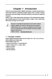
It delivers excellent performance with robust design conforming to ASRock's commitment to change without further notice. Chapter 3 and 4 contain basic BIOS setup and Support CD information. Because the ...endurance. Chapter 1 Introduction Thank you for floppy drive (1 x ribbon cable) 1 ASRock I/O shield 1 COM port bracket 1 MR card (optional) 4 ASRock website http://www.asrock.com 1.1 Package Contents ASRock M266A motherboard (Micro ATX form factor: 9.6" x 9.6", 24.4 x 24.4 cm) ASRock M266A Quick Setup Guide ASRock M266A Support CD 1 Cable for IDE devices (1 x ATA 66/100/133) 1...
It delivers excellent performance with robust design conforming to ASRock's commitment to change without further notice. Chapter 3 and 4 contain basic BIOS setup and Support CD information. Because the ...endurance. Chapter 1 Introduction Thank you for floppy drive (1 x ribbon cable) 1 ASRock I/O shield 1 COM port bracket 1 MR card (optional) 4 ASRock website http://www.asrock.com 1.1 Package Contents ASRock M266A motherboard (Micro ATX form factor: 9.6" x 9.6", 24.4 x 24.4 cm) ASRock M266A Quick Setup Guide ASRock M266A Support CD 1 Cable for IDE devices (1 x ATA 66/100/133) 1...

User Manual
Page 5
... ATA 133 Clock Generator: 100 MHz - 200MHz Memory: 2 slots for DDR: DDR1 and DDR2 (PC1600/ PC2100), Max. 2GB; 2 slots for two additional ASRock I/OTM: USB 2.0 ports upgrade (see CAUTION 2) PS/2: 1 keyboard port / 1 mouse port; 1 RJ 45 port; 4 rear default USB 2.0 ports;...Max. 2GB IDE: IDE1: ATA 133 / Ultra DMA Mode 6; SMBIOS 2.3.1 support; Can connect up events; ACPI 1.1 compliance wake up to protect CPU life (ASRock U-COP)(see CAUTION 3) OS: Microsoft® Windows® 98SE / ME / 2000 / XP compliant 5 1.2 Specifications Platform: Micro ATX form factor (9.6" x...
... ATA 133 Clock Generator: 100 MHz - 200MHz Memory: 2 slots for DDR: DDR1 and DDR2 (PC1600/ PC2100), Max. 2GB; 2 slots for two additional ASRock I/OTM: USB 2.0 ports upgrade (see CAUTION 2) PS/2: 1 keyboard port / 1 mouse port; 1 RJ 45 port; 4 rear default USB 2.0 ports;...Max. 2GB IDE: IDE1: ATA 133 / Ultra DMA Mode 6; SMBIOS 2.3.1 support; Can connect up events; ACPI 1.1 compliance wake up to protect CPU life (ASRock U-COP)(see CAUTION 3) OS: Microsoft® Windows® 98SE / ME / 2000 / XP compliant 5 1.2 Specifications Platform: Micro ATX form factor (9.6" x...
User Manual
Page 6
To improve heat dissipation, remember to perform over clocking. It may cause the instability of M266A is set to spray thermal grease between the CPU and the heatsink when you resume the system. When the CPU frequency of the system or ... the PC system. 2. While CPU overheat is not recommended to Microsoft® official document at http://www.microsoft.com/HWDEV/BUS/usb/USB2support.asp 3. Although M266A offers stepless control, it is detected, the system will also be overclocked proportionally. Please refer to perform over clocking, other than the recommended CPU bus...
To improve heat dissipation, remember to perform over clocking. It may cause the instability of M266A is set to spray thermal grease between the CPU and the heatsink when you resume the system. When the CPU frequency of the system or ... the PC system. 2. While CPU overheat is not recommended to Microsoft® official document at http://www.microsoft.com/HWDEV/BUS/usb/USB2support.asp 3. Although M266A offers stepless control, it is detected, the system will also be overclocked proportionally. Please refer to perform over clocking, other than the recommended CPU bus...
User Manual
Page 7
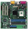
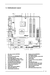
... AUX1 Super I/O AUDIO CODEC 2MB BIOS AMR1 Accelerated Graphics Port PCI 1 01 23 01 23 CMOS Battery CLRCMOS1 PCI 2 PCI 3 VIA South Bridge CHA_FAN1 SPEAKER1 M266A USB45 IR1 PLED PWRBTN PANEL1 PS2_USB_PWR1 HDLED RST FLOPPY1 27 17 9 16 15 10 18 26 16 13 14 22 12 1 ATX power connector (ATXPWR1...
... AUX1 Super I/O AUDIO CODEC 2MB BIOS AMR1 Accelerated Graphics Port PCI 1 01 23 01 23 CMOS Battery CLRCMOS1 PCI 2 PCI 3 VIA South Bridge CHA_FAN1 SPEAKER1 M266A USB45 IR1 PLED PWRBTN PANEL1 PS2_USB_PWR1 HDLED RST FLOPPY1 27 17 9 16 15 10 18 26 16 13 14 22 12 1 ATX power connector (ATXPWR1...

User Manual
Page 9
... motherboard fits into the holes indicated by the edges and do so may damage the motherboard. 2.2 Pre-installation Precautions 1. Before you handle components. 3. Chapter 2 Installation M266A is a Micro ATX form factor (9.6" x 9.6", 24.4 x 24.4 cm) motherboard. Whenever you and damages to ensure that comes with the component. 9 Failure to do not touch...
... motherboard fits into the holes indicated by the edges and do so may damage the motherboard. 2.2 Pre-installation Precautions 1. Before you handle components. 3. Chapter 2 Installation M266A is a Micro ATX form factor (9.6" x 9.6", 24.4 x 24.4 cm) motherboard. Whenever you and damages to ensure that comes with the component. 9 Failure to do not touch...

User Manual
Page 10
When the CPU is locked. Step 1 Step 2, 3 Step 4 2.4 Installation of CPU fan and heatsink. 10 For proper installation, please kindly refer to the instruction manuals of vendors of CPU Fan and Heatsink Intel® Pentium 4® and Celeron® CPU requires larger heatsink and cooling fan. Step 3. Carefully insert the CPU into the socket to secure the CPU. The lever clicks on the socket while you push down the socket lever to avoid bending of the socket lever. Step 2. Position the CPU directly above the socket such that the CPU and the heatsink are securely ...
When the CPU is locked. Step 1 Step 2, 3 Step 4 2.4 Installation of CPU fan and heatsink. 10 For proper installation, please kindly refer to the instruction manuals of vendors of CPU Fan and Heatsink Intel® Pentium 4® and Celeron® CPU requires larger heatsink and cooling fan. Step 3. Carefully insert the CPU into the socket to secure the CPU. The lever clicks on the socket while you push down the socket lever to avoid bending of the socket lever. Step 2. Position the CPU directly above the socket such that the CPU and the heatsink are securely ...

User Manual
Page 11
Step 1. Align a DIMM on the slot such that the notch on the DIMM matches the break on the slot. Firmly insert the DIMM into the slot until the retaining clip snap back in place and the DIMM is not recommended to disconnect power supply before adding or removing DIMMs or the system components. 168-pin RAM 184-pin RAM The 168-pin SDRAM DIMM slot (black) and 184-pin DDR DIMM slot (blue) can be easily distinguished by pressing the retaining clips outward. To optimize the compatibility, it is properly seated. 11 Step 2. Please do not use two different models of Memory Modules ...
Step 1. Align a DIMM on the slot such that the notch on the DIMM matches the break on the slot. Firmly insert the DIMM into the slot until the retaining clip snap back in place and the DIMM is not recommended to disconnect power supply before adding or removing DIMMs or the system components. 168-pin RAM 184-pin RAM The 168-pin SDRAM DIMM slot (black) and 184-pin DDR DIMM slot (blue) can be easily distinguished by pressing the retaining clips outward. To optimize the compatibility, it is properly seated. 11 Step 2. Please do not use two different models of Memory Modules ...
User Manual
Page 12
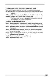
PCI slots: PCI slots are 3 PCI slots, 1 AMR slot, and 1 AGP slot on the slot. The ASRock AGP slot has a special locking mechanism which can securely fasten the graphics card inserted. Step 2. Step 3. Replace the system cover. 12 AGP slot: The AGP ... use . Step 4. Installing an expansion card Step 1. Keep the screws for the card. Remove the system unit cover (if your motherboard is completely seated on M266A motherboard. 2.6 Expansion Slots (PCI, AMR, and AGP Slots) There are used to use . Align the card connector with screws. Step 5.
PCI slots: PCI slots are 3 PCI slots, 1 AMR slot, and 1 AGP slot on the slot. The ASRock AGP slot has a special locking mechanism which can securely fasten the graphics card inserted. Step 2. Step 3. Replace the system cover. 12 AGP slot: The AGP ... use . Step 4. Installing an expansion card Step 1. Keep the screws for the card. Remove the system unit cover (if your motherboard is completely seated on M266A motherboard. 2.6 Expansion Slots (PCI, AMR, and AGP Slots) There are used to use . Align the card connector with screws. Step 5.

User Manual
Page 13
The illustration shows a 3-pin jumper whose pin1 and pin2 are setup. Note: To select +5VSB, it requires 2 Amp and higher standby current provided by using metal material, e.g., a paper clip. The data in the CMOS. To clear and reset the system parameters to enable (see p.7 item 17) Clear CMOS solder points Note: These solder points allow you to remove the paper clip after clearing the CMOS. 13 Please remember to clear the data in the CMOS includes system setup information such as the system password, date, time, and the system setup parameters. If no jumper cap is placed ...
The illustration shows a 3-pin jumper whose pin1 and pin2 are setup. Note: To select +5VSB, it requires 2 Amp and higher standby current provided by using metal material, e.g., a paper clip. The data in the CMOS. To clear and reset the system parameters to enable (see p.7 item 17) Clear CMOS solder points Note: These solder points allow you to remove the paper clip after clearing the CMOS. 13 Please remember to clear the data in the CMOS includes system setup information such as the system password, date, time, and the system setup parameters. If no jumper cap is placed ...

User Manual
Page 14
If the rear USB ports are NOT jumpers. Infrared module connector (5-pin IR1) (see p.7 item 13) ASRock I/OTM provides you 4 default USB 2.0 ports on the floppy ribbon cable with Pin1 Primary IDE connector (Blue) Secondary IDE connector (Black) (39-pin IDE1, see p.7 ...
If the rear USB ports are NOT jumpers. Infrared module connector (5-pin IR1) (see p.7 item 13) ASRock I/OTM provides you 4 default USB 2.0 ports on the floppy ribbon cable with Pin1 Primary IDE connector (Blue) Secondary IDE connector (Black) (39-pin IDE1, see p.7 ...

User Manual
Page 15
This connector accommodates several system front panel functions. Connect the fan cable to the connector matching the black wire to the connector. Connect an ATX power supply to the ground pin. Connect the fan cable to the connector matching the black wire to receive stereo audio input from sound sources such as AUX1 a CD-ROM, DVD-ROM, TV tuner card, or MPEG card. Internal audio connectors (4-pin CD1, 4-pin AUX1) (CD1: see p.7 item 24) (AUX1: see p.7 item 23) Front panel audio connector (9-pin AUDIO1) (see p.7 item 20) System panel connector (9-pin PANEL1) (see p.7 item ...
This connector accommodates several system front panel functions. Connect the fan cable to the connector matching the black wire to the connector. Connect an ATX power supply to the ground pin. Connect the fan cable to the connector matching the black wire to receive stereo audio input from sound sources such as AUX1 a CD-ROM, DVD-ROM, TV tuner card, or MPEG card. Internal audio connectors (4-pin CD1, 4-pin AUX1) (CD1: see p.7 item 24) (AUX1: see p.7 item 23) Front panel audio connector (9-pin AUDIO1) (see p.7 item 20) System panel connector (9-pin PANEL1) (see p.7 item ...
User Manual
Page 16
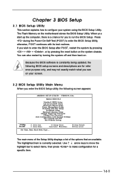
... Set Time, Date, Hard Disk Type . . . You can also restart by pressing the reset button on the motherboard stores the BIOS Setup Utility. VERSION 3.31a M266A BIOS P1.0 Standard CMOS Setup Advanced CMOS Setup Advanced Chipset Setup Power Management Setup PCI / Plug and Play Setup Peripheral Setup Hardware Monitor Setup Change...
... Set Time, Date, Hard Disk Type . . . You can also restart by pressing the reset button on the motherboard stores the BIOS Setup Utility. VERSION 3.31a M266A BIOS P1.0 Standard CMOS Setup Advanced CMOS Setup Advanced Chipset Setup Power Management Setup PCI / Plug and Play Setup Peripheral Setup Hardware Monitor Setup Change...
User Manual
Page 17
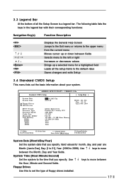
... IDE Devices BIOS Version Processor Type Processor Speed Cache Size Microcode Update Total Memory DDR1 DDR2 SDR1 SDR2 Apr 10 2003 Thu 20:07:40 M266A BIOS P1.00 Pentium (R) 4 Family CPU 2400 MHz 512 KB F24 / 0F 224 MB + 32 MB Share Memory 256 MB / 266 MHz None None None...
... IDE Devices BIOS Version Processor Type Processor Speed Cache Size Microcode Update Total Memory DDR1 DDR2 SDR1 SDR2 Apr 10 2003 Thu 20:07:40 M266A BIOS P1.00 Pentium (R) 4 Family CPU 2400 MHz 512 KB F24 / 0F 224 MB + 32 MB Share Memory 256 MB / 266 MHz None None None...
User Manual
Page 18
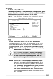
If the auto-detection fails, it may due to set the parameters of drive, Or Select [AUTO] to that you have the correct configuration information supplied by the drive manufacturer. VERSION 3.31a Primary IDE Master: [ Setup Help ] Type Cylinders Heads Write Precompensation Sectors Maximum Capacity LBA Mode Block Mode Fast Programmed I/O Modes 32 Bit Transfer Mode Ultra DMA Mode Auto Off Off Auto Off Auto Select how to set all HDD parameters automatically. After making your system, and each device on this sub-menu, press key to return to the upper menu, in the correct ...
If the auto-detection fails, it may due to set the parameters of drive, Or Select [AUTO] to that you have the correct configuration information supplied by the drive manufacturer. VERSION 3.31a Primary IDE Master: [ Setup Help ] Type Cylinders Heads Write Precompensation Sectors Maximum Capacity LBA Mode Block Mode Fast Programmed I/O Modes 32 Bit Transfer Mode Ultra DMA Mode Auto Off Off Auto Off Auto Select how to set all HDD parameters automatically. After making your system, and each device on this sub-menu, press key to return to the upper menu, in the correct ...

User Manual
Page 19
Make sure to set the PIO mode to enhance hard disk performance by optimizing the hard disk timing. 32 Bit Transfer Mode It allows user to enable 32-bit access to maximize the IDE hard disk data transfer rate. for Netware and UNIX user, select [Off] to suppress Ultra DMA capability. 19 Ultra DMA Mode Ultra DMA capability allows improved transfer speeds and data integrity for compatible IDE devices. Set to [Disabled] to disable the LBA mode. Heads This is used to configure the number of sectors per track. Cylinders This is used to configure the number of read data from the ...
Make sure to set the PIO mode to enhance hard disk performance by optimizing the hard disk timing. 32 Bit Transfer Mode It allows user to enable 32-bit access to maximize the IDE hard disk data transfer rate. for Netware and UNIX user, select [Off] to suppress Ultra DMA capability. 19 Ultra DMA Mode Ultra DMA capability allows improved transfer speeds and data integrity for compatible IDE devices. Set to [Disabled] to disable the LBA mode. Heads This is used to configure the number of sectors per track. Cylinders This is used to configure the number of read data from the ...

User Manual
Page 20
Boot-time Diagnostic Screen: If this to OS/2 operating system. Boot Device Priority F1:Help Esc:Previous Menu :Select Item +/-:Change Values Enter:Select Sub-Menu F9:Setup Defaults F10:Save & Exit Quick Boot This mode speeds up the boot-up to select the priority and order of the devices that your system searches for "Password Check". Configuration options: [Setup], [Always]. If [Always] option is selected, the "Password Check" is enabled, the screen will show CPU and hardware information during Power-On-Self-Test (POST) routine. Boot Device Priority Use this option...
Boot-time Diagnostic Screen: If this to OS/2 operating system. Boot Device Priority F1:Help Esc:Previous Menu :Select Item +/-:Change Values Enter:Select Sub-Menu F9:Setup Defaults F10:Save & Exit Quick Boot This mode speeds up the boot-up to select the priority and order of the devices that your system searches for "Password Check". Configuration options: [Setup], [Always]. If [Always] option is selected, the "Password Check" is enabled, the screen will show CPU and hardware information during Power-On-Self-Test (POST) routine. Boot Device Priority Use this option...
User Manual
Page 21
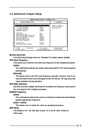
F1:Help Esc:Previous Menu :Select Item +/-:Change Values Enter:Select Sub-Menu F9:Setup Defaults F10:Save & Exit Spread Spectrum This field should always set to be "Disabled" for the installed processor. [Auto] The motherboard detects the jumper setup and sets the CPU host frequency automatically. [Manual] This allows user to set CPU host frequency manually. CPU Host Frequency This allows you to set the multiple that times the frontside bus frequency must equal to enable or disable the feature of VGA cards. 21 SDRAM Frequency [Auto] The motherboard detects the memory module(s) ...
F1:Help Esc:Previous Menu :Select Item +/-:Change Values Enter:Select Sub-Menu F9:Setup Defaults F10:Save & Exit Spread Spectrum This field should always set to be "Disabled" for the installed processor. [Auto] The motherboard detects the jumper setup and sets the CPU host frequency automatically. [Manual] This allows user to set CPU host frequency manually. CPU Host Frequency This allows you to set the multiple that times the frontside bus frequency must equal to enable or disable the feature of VGA cards. 21 SDRAM Frequency [Auto] The motherboard detects the memory module(s) ...