User Manual
Page 3
... Motherboard Layout 7 1.4 ASRock I/OTM 8 2 Installation 9 2.1 Screw Holes 9 2.2 Pre-installation Precautions 9 2.3 CPU Installation 10 2.4 Installation of CPU fan and Heatsink 10 2.5 Installation of Memory Modules (DIMM 11 2.6 Expansion Slots 12 2.7 Jumpers Setup 13 2.8 Connectors 14 3 BIOS Setup 16 3.1 BIOS Setup Utility 16 3.2 BIOS Setup Utility Main Menu 16 3.3 Legend Bar 17 3.4 Standard CMOS Setup 17 3.5 Advanced CMOS Setup 20 3.6 Advanced Chipset Setup 21 3.7 Power Management Setup 23 3.8 PCI / Plug and Play Setup 24 3.9 Peripheral Setup 25 3.10 Hardware Monitor Setup...
... Motherboard Layout 7 1.4 ASRock I/OTM 8 2 Installation 9 2.1 Screw Holes 9 2.2 Pre-installation Precautions 9 2.3 CPU Installation 10 2.4 Installation of CPU fan and Heatsink 10 2.5 Installation of Memory Modules (DIMM 11 2.6 Expansion Slots 12 2.7 Jumpers Setup 13 2.8 Connectors 14 3 BIOS Setup 16 3.1 BIOS Setup Utility 16 3.2 BIOS Setup Utility Main Menu 16 3.3 Legend Bar 17 3.4 Standard CMOS Setup 17 3.5 Advanced CMOS Setup 20 3.6 Advanced Chipset Setup 21 3.7 Power Management Setup 23 3.8 PCI / Plug and Play Setup 24 3.9 Peripheral Setup 25 3.10 Hardware Monitor Setup...
User Manual
Page 4
... change without further notice. Because the motherboard specifications and the BIOS software might be updated, the content of this manual occur, the updated version will be available on ASRock website without notice. Chapter 3 and 4 contain basic BIOS setup and Support CD information. ASRock website http://www.asrock.com 1.1 Package Contents ASRock M266A motherboard (Micro ATX form factor: 9.6" x 9.6", 24.4 x 24.4 cm) ASRock M266A Quick Setup Guide ASRock M266A Support CD 1 Cable for IDE devices (1 x ATA 66/100/133) 1 Cable for purchasing ASRock M266A motherboard...
... change without further notice. Because the motherboard specifications and the BIOS software might be updated, the content of this manual occur, the updated version will be available on ASRock website without notice. Chapter 3 and 4 contain basic BIOS setup and Support CD information. ASRock website http://www.asrock.com 1.1 Package Contents ASRock M266A motherboard (Micro ATX form factor: 9.6" x 9.6", 24.4 x 24.4 cm) ASRock M266A Quick Setup Guide ASRock M266A Support CD 1 Cable for IDE devices (1 x ATA 66/100/133) 1 Cable for purchasing ASRock M266A motherboard...

User Manual
Page 5
...45 port; 4 rear default USB 2.0 ports; 1 VGA port; 1 parallel port: ECP/EPP support; CPU frequency stepless control (only for two additional ASRock I/OTM: USB 2.0 ports upgrade (see CAUTION 1); South Bridge: Supports USB 2.0, ATA 133 Clock Generator: 100 MHz - 200MHz Memory: 2 slots for DDR: DDR1 and DDR2 (PC1600/ PC2100), Max. 2GB; 2 slots for Intel® Pentium® 4 / Celeron® processor Chipsets: North Bridge: VIA P4M266A, FSB@533 MHz; CPU overheat shutdown to 4 IDE devices Floppy Port: Supports floppy disk drive Audio: 2 channels AC'97 Audio LAN...
...45 port; 4 rear default USB 2.0 ports; 1 VGA port; 1 parallel port: ECP/EPP support; CPU frequency stepless control (only for two additional ASRock I/OTM: USB 2.0 ports upgrade (see CAUTION 1); South Bridge: Supports USB 2.0, ATA 133 Clock Generator: 100 MHz - 200MHz Memory: 2 slots for DDR: DDR1 and DDR2 (PC1600/ PC2100), Max. 2GB; 2 slots for Intel® Pentium® 4 / Celeron® processor Chipsets: North Bridge: VIA P4M266A, FSB@533 MHz; CPU overheat shutdown to 4 IDE devices Floppy Port: Supports floppy disk drive Audio: 2 channels AC'97 Audio LAN...
User Manual
Page 6
... the CPU fan on the motherboard functions properly before you install the PC system. 2. Power Management for USB 2.0 works fine under Microsoft® Windows® 98/ME/2000. Please refer to perform over clocking, other than the recommended CPU bus frequencies may not work properly under Microsoft® Windows® XP. CAUTION! 1. To improve heat dissipation, remember to perform over clocking. Although M266A offers stepless control, it...
... the CPU fan on the motherboard functions properly before you install the PC system. 2. Power Management for USB 2.0 works fine under Microsoft® Windows® 98/ME/2000. Please refer to perform over clocking, other than the recommended CPU bus frequencies may not work properly under Microsoft® Windows® XP. CAUTION! 1. To improve heat dissipation, remember to perform over clocking. Although M266A offers stepless control, it...
User Manual
Page 7
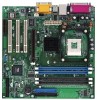
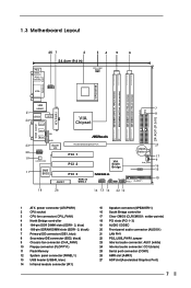
...IDE connector (IDE2, black) 9 Chassis fan connector (CHA_FAN1) 10 Floppy connector (FLOPPY1) 11 Flash Memory 12 System panel connector (PANEL1) 13 USB header (USB45, blue) 14 Infrared module connector (IR1) 15 Speaker connector (SPEAKER 1) 16 South Bridge controller 17 Clear CMOS (CLRCMOS1: solder points) 18 PCI slots (PCI 1- 3) 19 AUDIO CODEC 20 Front panel audio connector (AUDIO1) 21 LAN PHY 22 PS2_USB_PWR1 jumper 23 Internal audio connector: AUX1 (white) 24 Internal audio connector: CD1 (black) 25 Serial port connector (COM1) 26 AMR slot (AMR1) 27 AGP slot (Accelerated Graphics Port...
...IDE connector (IDE2, black) 9 Chassis fan connector (CHA_FAN1) 10 Floppy connector (FLOPPY1) 11 Flash Memory 12 System panel connector (PANEL1) 13 USB header (USB45, blue) 14 Infrared module connector (IR1) 15 Speaker connector (SPEAKER 1) 16 South Bridge controller 17 Clear CMOS (CLRCMOS1: solder points) 18 PCI slots (PCI 1- 3) 19 AUDIO CODEC 20 Front panel audio connector (AUDIO1) 21 LAN PHY 22 PS2_USB_PWR1 jumper 23 Internal audio connector: AUX1 (white) 24 Internal audio connector: CD1 (black) 25 Serial port connector (COM1) 26 AMR slot (AMR1) 27 AGP slot (Accelerated Graphics Port...

User Manual
Page 9
... before touching any component, place it . Whenever you remove any component. 2. Failure to use a grounded wrist strap or touch a safety grounded object before installing or removing the motherboard. Chapter 2 Installation M266A is a Micro ATX form factor (9.6" x 9.6", 24.4 x 24.4 cm) motherboard. Unplug the power cord from the wall socket before installing or removing the motherboard. Do not over-tighten the screws! Hold components by circles to...
... before touching any component, place it . Whenever you remove any component. 2. Failure to use a grounded wrist strap or touch a safety grounded object before installing or removing the motherboard. Chapter 2 Installation M266A is a Micro ATX form factor (9.6" x 9.6", 24.4 x 24.4 cm) motherboard. Unplug the power cord from the wall socket before installing or removing the motherboard. Do not over-tighten the screws! Hold components by circles to...

User Manual
Page 11
... optimize the compatibility, it is properly seated. 11 Please do not use two different models of Memory Modules (DIMM) SDRAM (Synchronous DRAM) DIMM (Dual In-line Memory Module) has 168 pinsand DDR (Double Data Rate) SDRAM DIMM has 184 pins. Step 1. Align a DIMM on the slot such that the...power supply before adding or removing DIMMs or the system components. 168-pin RAM 184-pin RAM The 168-pin SDRAM DIMM slot (black) and 184-pin DDR DIMM slot (blue) can be easily distinguished by pressing the retaining clips outward. Please make sure to use both 168-pin SDRAM DIMM and 184-pin...
... optimize the compatibility, it is properly seated. 11 Please do not use two different models of Memory Modules (DIMM) SDRAM (Synchronous DRAM) DIMM (Dual In-line Memory Module) has 168 pinsand DDR (Double Data Rate) SDRAM DIMM has 184 pins. Step 1. Align a DIMM on the slot such that the...power supply before adding or removing DIMMs or the system components. 168-pin RAM 184-pin RAM The 168-pin SDRAM DIMM slot (black) and 184-pin DDR DIMM slot (blue) can be easily distinguished by pressing the retaining clips outward. Please make sure to use both 168-pin SDRAM DIMM and 184-pin...
User Manual
Page 12
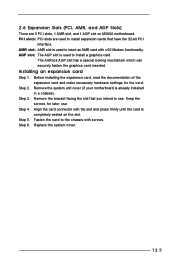
... AMR card with v.92 Modem functionality. Installing an expansion card Step 1. Before installing the expansion card, read the documentation of the expansion card and make necessary hardware settings for later use . Align the card connector with the slot and press firmly until the card is already installed in a chassis). Step 5. Step 2. Replace the system cover. 12 Step 4. Remove the bracket facing the slot that have the 32-bit PCI...
... AMR card with v.92 Modem functionality. Installing an expansion card Step 1. Before installing the expansion card, read the documentation of the expansion card and make necessary hardware settings for later use . Align the card connector with the slot and press firmly until the card is already installed in a chassis). Step 5. Step 2. Replace the system cover. 12 Step 4. Remove the bracket facing the slot that have the 32-bit PCI...

User Manual
Page 15
... as AUX1 a CD-ROM, DVD-ROM, TV tuner card, or MPEG card. This connector supports a serial port module. 15 Internal audio connectors (4-pin CD1, 4-pin AUX1) (CD1: see p.7 item 24) (AUX1: see p.7 item 23) Front panel audio connector (9-pin AUDIO1) (see p.7 item 20) System panel connector (9-pin PANEL1) (see p.7 item 12) External speaker connector (4-pin SPEAKER 1) (see p.7 item 15) Chassis fan connector (3-pin CHA_FAN1) (see p.7 item 9) CPU fan connector (3-pin CPU_FAN1) (see p.7 item 3) ATX power connector (20-pin ATXPWR1) (see p.7 item 1) Serial port connector (9-pin COM1) (see p.7 item...
... as AUX1 a CD-ROM, DVD-ROM, TV tuner card, or MPEG card. This connector supports a serial port module. 15 Internal audio connectors (4-pin CD1, 4-pin AUX1) (CD1: see p.7 item 24) (AUX1: see p.7 item 23) Front panel audio connector (9-pin AUDIO1) (see p.7 item 20) System panel connector (9-pin PANEL1) (see p.7 item 12) External speaker connector (4-pin SPEAKER 1) (see p.7 item 15) Chassis fan connector (3-pin CHA_FAN1) (see p.7 item 9) CPU fan connector (3-pin CPU_FAN1) (see p.7 item 3) ATX power connector (20-pin ATXPWR1) (see p.7 item 1) Serial port connector (9-pin COM1) (see p.7 item...
User Manual
Page 16
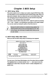
... selected. You can also restart by pressing the reset button on your system using the BIOS Setup Utility. If you wish to enter the BIOS Setup after POST, restart the system by pressing + + , or by turning the system off and then back on the motherboard stores the BIOS Setup Utility. VERSION 3.31a M266A BIOS P1.0 Standard CMOS Setup Advanced CMOS Setup Advanced Chipset Setup Power Management Setup PCI / Plug and Play Setup Peripheral Setup Hardware Monitor Setup Change Supervisor Password Change User Password Auto Configuration with its test routines.
... selected. You can also restart by pressing the reset button on your system using the BIOS Setup Utility. If you wish to enter the BIOS Setup after POST, restart the system by pressing + + , or by turning the system off and then back on the motherboard stores the BIOS Setup Utility. VERSION 3.31a M266A BIOS P1.0 Standard CMOS Setup Advanced CMOS Setup Advanced Chipset Setup Power Management Setup PCI / Plug and Play Setup Peripheral Setup Hardware Monitor Setup Change Supervisor Password Change User Password Auto Configuration with its test routines.
User Manual
Page 17
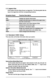
...:Second] Set the system to move between the Month, Day and Year fields. Floppy Drives Use this to 2099). Use keys to the time that you specify. 3.3 Legend Bar At the bottom of floppy drives installed. 17 VERSION 3.31a Standard CMOS Setup [ Setup Help ] System Date System Time Floppy Drives IDE Devices BIOS Version Processor Type Processor Speed Cache Size Microcode Update Total Memory DDR1 DDR2 SDR1 SDR2 Apr 10 2003 Thu 20:07:40 M266A BIOS P1...
...:Second] Set the system to move between the Month, Day and Year fields. Floppy Drives Use this to 2099). Use keys to the time that you specify. 3.3 Legend Bar At the bottom of floppy drives installed. 17 VERSION 3.31a Standard CMOS Setup [ Setup Help ] System Date System Time Floppy Drives IDE Devices BIOS Version Processor Type Processor Speed Cache Size Microcode Update Total Memory DDR1 DDR2 SDR1 SDR2 Apr 10 2003 Thu 20:07:40 M266A BIOS P1...
User Manual
Page 18
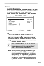
... LBA Mode Block Mode Fast Programmed I/O Modes 32 Bit Transfer Mode Ultra DMA Mode Auto Off Off Auto Off Auto Select how to set the parameters of drive, Or Select [AUTO] to that you have the correct configuration information supplied by the drive manufacturer. Before attempting to configure a hard disk drive, make sure you configured. [USER]: It allows user to manually enter the number of the IDE Drive. IDE Devices Use this sub-menu. There are the configuration options. Below are two IDE channels...
... LBA Mode Block Mode Fast Programmed I/O Modes 32 Bit Transfer Mode Ultra DMA Mode Auto Off Off Auto Off Auto Select how to set the parameters of drive, Or Select [AUTO] to that you have the correct configuration information supplied by the drive manufacturer. Before attempting to configure a hard disk drive, make sure you configured. [USER]: It allows user to manually enter the number of the IDE Drive. IDE Devices Use this sub-menu. There are the configuration options. Below are two IDE channels...

User Manual
Page 20
... at start-up and BIOS setup. Boot Device Priority F1:Help Esc:Previous Menu :Select Item +/-:Change Values Enter:Select Sub-Menu F9:Setup Defaults F10:Save & Exit Quick Boot This mode speeds up the boot-up . If [Setup] option is selected, the "Password Check" is enabled, the screen will show CPU and hardware information during Power-On-Self-Test (POST) routine. VERSION 3.31a Advanced CMOS Setup [ Setup Help ] Quick Boot Mode Boot Up Num-Lock Boot To OS/2 Password Check Boot From Network Enabled...
... at start-up and BIOS setup. Boot Device Priority F1:Help Esc:Previous Menu :Select Item +/-:Change Values Enter:Select Sub-Menu F9:Setup Defaults F10:Save & Exit Quick Boot This mode speeds up the boot-up . If [Setup] option is selected, the "Password Check" is enabled, the screen will show CPU and hardware information during Power-On-Self-Test (POST) routine. VERSION 3.31a Advanced CMOS Setup [ Setup Help ] Quick Boot Mode Boot Up Num-Lock Boot To OS/2 Password Check Boot From Network Enabled...
User Manual
Page 21
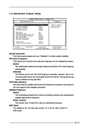
... Advanced Chipset Setup AMIBIOS SETUP UTILITY - SDRAM Frequency [Auto] The motherboard detects the memory module(s) inserted and automatically assigns appropriate frequency. [other values] This allows user to the core speed of spread spectrum. VERSION 3.31a Advanced Chipset Setup [ Setup Help ] Spread Spectrum CPU Host Frequency Actual Frequency CPU Ratio Selection SDRAM Frequency AGP Mode AGP Aperture Size OnChip VGA Frame Buffer Size CPU Read DRAM Fast Ready Read Around Write CPU R/W DRAM 0WS PCI Delay Transaction USB Controller USB Device Legacy Support Disabled Auto 133MHz Locked...
... Advanced Chipset Setup AMIBIOS SETUP UTILITY - SDRAM Frequency [Auto] The motherboard detects the memory module(s) inserted and automatically assigns appropriate frequency. [other values] This allows user to the core speed of spread spectrum. VERSION 3.31a Advanced Chipset Setup [ Setup Help ] Spread Spectrum CPU Host Frequency Actual Frequency CPU Ratio Selection SDRAM Frequency AGP Mode AGP Aperture Size OnChip VGA Frame Buffer Size CPU Read DRAM Fast Ready Read Around Write CPU R/W DRAM 0WS PCI Delay Transaction USB Controller USB Device Legacy Support Disabled Auto 133MHz Locked...
User Manual
Page 22
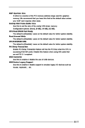
... will free the PCI Bus when the CPU is [Disabled]. USB Device Legacy Support Use this to emulate legacy I/O devices such as mouse, keyboard,... CPU Read DRAM Fast Ready The default is accessing 8-bit ISA cards. Leave on the default value for graphics memory. etc. 22 OnChip VGA Frame Buffer Size Use this to enable or disable support to set the size of the onchip VGA share memory. AGP Aperture Size It refers to enable or disable the use of USB devices. Configuration options: [None], [8 MB], [16 MB], [32 MB]. USB Controller Use...
... will free the PCI Bus when the CPU is [Disabled]. USB Device Legacy Support Use this to emulate legacy I/O devices such as mouse, keyboard,... CPU Read DRAM Fast Ready The default is accessing 8-bit ISA cards. Leave on the default value for graphics memory. etc. 22 OnChip VGA Frame Buffer Size Use this to enable or disable support to set the size of the onchip VGA share memory. AGP Aperture Size It refers to enable or disable the use of USB devices. Configuration options: [None], [8 MB], [16 MB], [32 MB]. USB Controller Use...

User Manual
Page 23
... the power-soft-off mode. VERSION 3.31a Standard CMOS Setup [ Setup Help ] Suspend To RAM Repost Video on S3 Resume Restore on the system from the power-soft-off when the power recovers. Select [Auto] will enable this to enable or disable keyboard to set the power state after an unexpected AC / Power loss. If [Power Off] is selected, the AC power resumes and the system starts to -RAM feature. Keyboard Power On Use this...
... the power-soft-off mode. VERSION 3.31a Standard CMOS Setup [ Setup Help ] Suspend To RAM Repost Video on S3 Resume Restore on the system from the power-soft-off when the power recovers. Select [Auto] will enable this to enable or disable keyboard to set the power state after an unexpected AC / Power loss. If [Power Off] is selected, the AC power resumes and the system starts to -RAM feature. Keyboard Power On Use this...

User Manual
Page 25
... Port Mode EPP Version Parallel Port IRQ Parallel Port DMA Channel OnBoard Midi Port Midi IRQ Select OnBoard Game Port OnBoard IDE OnBoard LAN OnBoard AC' 97 Audio Auto Auto Disabled Auto ECP + EPPl 1.9 Auto Auto Disabled 5 200h Both Enabled Auto to enable or disable the onboard infrared port feature. F1:Help Esc:Previous Menu :Select Item +/-:Change Values Enter:Select Sub-Menu F9:Setup Defaults F10:Save & Exit OnBoard FDC Use this to select Midi IRQ. Midi IRQ Select Use this to set addresses for the onboard serial ports or disable serial ports. Configuration options...
... Port Mode EPP Version Parallel Port IRQ Parallel Port DMA Channel OnBoard Midi Port Midi IRQ Select OnBoard Game Port OnBoard IDE OnBoard LAN OnBoard AC' 97 Audio Auto Auto Disabled Auto ECP + EPPl 1.9 Auto Auto Disabled 5 200h Both Enabled Auto to enable or disable the onboard infrared port feature. F1:Help Esc:Previous Menu :Select Item +/-:Change Values Enter:Select Sub-Menu F9:Setup Defaults F10:Save & Exit OnBoard FDC Use this to select Midi IRQ. Midi IRQ Select Use this to set addresses for the onboard serial ports or disable serial ports. Configuration options...

User Manual
Page 26
If it is set to [Disabled], it will disable the both IDE channels. OnBoard AC'97 Audio Enable or disable onboard AC'97 audio feature. OnBoard LAN Enable or disable onboard LAN feature. OnBoard MC'97 Modem Enable or disable onboard MC'97 modem feature. 26 Or you may select [Both] to enable either the primary IDE channel or the secondary IDE channel. OnBoard IDE Select [Primary] or [Secondary] to enable both . Configuration options: [Disabled], [Primary], [Secondary], [Both].
If it is set to [Disabled], it will disable the both IDE channels. OnBoard AC'97 Audio Enable or disable onboard AC'97 audio feature. OnBoard LAN Enable or disable onboard LAN feature. OnBoard MC'97 Modem Enable or disable onboard MC'97 modem feature. 26 Or you may select [Both] to enable either the primary IDE channel or the secondary IDE channel. OnBoard IDE Select [Primary] or [Secondary] to enable both . Configuration options: [Disabled], [Primary], [Secondary], [Both].

User Manual
Page 27
... the memory. 3.10 Hardware Monitor Setup You can select "Hardware Monitor Setup" to 6 alphanumeric characters combination. 3.12 Auto Configuration with Optimal Settings When you select this option, it will pop up a dialog box that you have made and exit the BIOS Setup Utility. 3.14 Exit Without Saving Select this item and press to save the changes that lets you install optimized defaults for CPU temperature, Motherboard temperature, CPU fan speed, and critical voltage.
... the memory. 3.10 Hardware Monitor Setup You can select "Hardware Monitor Setup" to 6 alphanumeric characters combination. 3.12 Auto Configuration with Optimal Settings When you select this option, it will pop up a dialog box that you have made and exit the BIOS Setup Utility. 3.14 Exit Without Saving Select this item and press to save the changes that lets you install optimized defaults for CPU temperature, Motherboard temperature, CPU fan speed, and critical voltage.

User Manual
Page 28
... with the motherboard contains necessary drivers and useful utilities that the motherboard supports. The CD automatically displays the Main Menu if "AUTORUN" is enabled in this demo program, you can run Microsoft® Media Player® to play the file. 4.2.5 Contact Information If you may contact your dealer for more about ASRock, welcome to your CD-ROM drive. You can find the file through the...
... with the motherboard contains necessary drivers and useful utilities that the motherboard supports. The CD automatically displays the Main Menu if "AUTORUN" is enabled in this demo program, you can run Microsoft® Media Player® to play the file. 4.2.5 Contact Information If you may contact your dealer for more about ASRock, welcome to your CD-ROM drive. You can find the file through the...


