
User Manual
Page 1
MOTHERBOARD K8Upgrade-760GX User Manual Version 1.0 Published August 2004 Copyright©2004 ASRock INC. All rights reserved. 1
MOTHERBOARD K8Upgrade-760GX User Manual Version 1.0 Published August 2004 Copyright©2004 ASRock INC. All rights reserved. 1

User Manual
Page 3
... 2.7 Serial ATA (SATA) Hard Disks Installation 19 2.8 Hot Plug Function for SATA HDDs 19 2.9 Making An SATA Driver Diskette 20 3. Contents 1. Introduction 5 1.1 Package Contents 5 1.2 Specifications 6 1.3 Motherboard Layout 9 1.4 ASRock 8CH I/O 10 2.
... 2.7 Serial ATA (SATA) Hard Disks Installation 19 2.8 Hot Plug Function for SATA HDDs 19 2.9 Making An SATA Driver Diskette 20 3. Contents 1. Introduction 5 1.1 Package Contents 5 1.2 Specifications 6 1.3 Motherboard Layout 9 1.4 ASRock 8CH I/O 10 2.
User Manual
Page 5
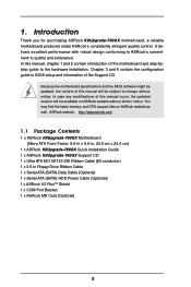
... as well. 1. You may find the latest memory and CPU support lists on ASRock website without notice. ASRock website http://www.asrock.com 1.1 Package Contents 1 x ASRock K8Upgrade-760GX Motherboard (Micro ATX Form Factor: 9.0-in x 9.6-in, 22.9 cm x 24.4 cm) 1 x ASRock K8Upgrade-760GX Quick Installation Guide 1 x ASRock K8Upgrade-760GX Support CD 1 x Ultra ATA 66/100/133 IDE Ribbon Cable (80-conductor) 1 x 3.5-in Floppy Drive...
... as well. 1. You may find the latest memory and CPU support lists on ASRock website without notice. ASRock website http://www.asrock.com 1.1 Package Contents 1 x ASRock K8Upgrade-760GX Motherboard (Micro ATX Form Factor: 9.0-in x 9.6-in, 22.9 cm x 24.4 cm) 1 x ASRock K8Upgrade-760GX Quick Installation Guide 1 x ASRock K8Upgrade-760GX Support CD 1 x Ultra ATA 66/100/133 IDE Ribbon Cable (80-conductor) 1 x 3.5-in Floppy Drive...

User Manual
Page 6
... advanced 64-bit AMD AthlonTM 64 and 32-bit Sempron Processor Supports AMD's Cool 'n' QuietTM Technology (see CAUTION 1) Chipsets: North Bridge: SiS 760GX Chipset FSB @ 800 MHz / 1.6 GT/s South Bridge: SiS 964 Chipset Supports USB 2.0, ATA 133, SATA 1.5Gb/s Memory: 2 x ... DirectX 8.1 LAN: Speed: 802.3u (10/100 Ethernet), Supports Wake-On-LAN Hardware Monitor: CPU Temperature Sensing Motherboard Temperature Sensing CPU Overheat Shutdown to Protect CPU Life (ASRock U-COP)(see CAUTION 2) CPU Fan Tachometer Chassis Fan Tachometer Voltage Monitoring: +12V, +5V, +3.3V, Vcore Future...
... advanced 64-bit AMD AthlonTM 64 and 32-bit Sempron Processor Supports AMD's Cool 'n' QuietTM Technology (see CAUTION 1) Chipsets: North Bridge: SiS 760GX Chipset FSB @ 800 MHz / 1.6 GT/s South Bridge: SiS 964 Chipset Supports USB 2.0, ATA 133, SATA 1.5Gb/s Memory: 2 x ... DirectX 8.1 LAN: Speed: 802.3u (10/100 Ethernet), Supports Wake-On-LAN Hardware Monitor: CPU Temperature Sensing Motherboard Temperature Sensing CPU Overheat Shutdown to Protect CPU Life (ASRock U-COP)(see CAUTION 2) CPU Fan Tachometer Chassis Fan Tachometer Voltage Monitoring: +12V, +5V, +3.3V, Vcore Future...

User Manual
Page 7
... page 38 to enable AMD's Cool 'n' QuietTM technology. 2. Do NOT use a 3.3V AGP card on the AGP slot of the system or damage the CPU. 7 ASRock I/O PlusTM: 1 PS/2 Mouse Port, 1 PS/2 Keyboard Port 1 VGA Port 1 Parallel Port (ECP/EPP Support) 6 Ready-to-Use USB 2.0 Ports 1 RJ-45 Port... stepless control, it is not recommended to enable AMD's Cool 'n' QuietTM technology under Windows system. Although this motherboard! See APPENDIX on the motherboard functions properly and unplug the power cord, then plug it is detected, the system will automatically shutdown. While CPU overheat is ...
... page 38 to enable AMD's Cool 'n' QuietTM technology. 2. Do NOT use a 3.3V AGP card on the AGP slot of the system or damage the CPU. 7 ASRock I/O PlusTM: 1 PS/2 Mouse Port, 1 PS/2 Keyboard Port 1 VGA Port 1 Parallel Port (ECP/EPP Support) 6 Ready-to-Use USB 2.0 Ports 1 RJ-45 Port... stepless control, it is not recommended to enable AMD's Cool 'n' QuietTM technology under Windows system. Although this motherboard! See APPENDIX on the motherboard functions properly and unplug the power cord, then plug it is detected, the system will automatically shutdown. While CPU overheat is ...

User Manual
Page 8
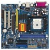
J8 Jumpers 8 1.3 Motherboard Layout PS2 Keyboard 12 3 PS2_USB_PW1 PS2 1 Mouse CPU_FAN1 ATX12V1 4 56 7 22.9cm (9.0-in) 89 J15 1 IR1 1 2Mb BIOS Super I/O PARALLEL PORT ATXPWR1 DDR400 DDR2 (64/... 2.0 T: USB0 B: USB1 Top: RJ-45 Shared 1 USB 2.0 T: USB4 B: USB5 USB45 CD1 1 1 J7 J8 FSB800 1 1 J5 J6 1 1 J3 J4 SiS 760GX Chipset 5.1CH 1 1 J1 J2 AUDIO1 1 JR1 JL1 AUX1 FUTURE_CPU_PORT1 1 J9 1 J10 K8Upgrade-760GX 1.5V_AGP1 LAN PHY PCI 1 AGP 8X AUDIO CODEC AMR1 PCI 2 1 COM1 CMOS Battery CLRCMOS2 1 USB2.0 FLOPPY1 IDE2 IDE1 SiS 964...
J8 Jumpers 8 1.3 Motherboard Layout PS2 Keyboard 12 3 PS2_USB_PW1 PS2 1 Mouse CPU_FAN1 ATX12V1 4 56 7 22.9cm (9.0-in) 89 J15 1 IR1 1 2Mb BIOS Super I/O PARALLEL PORT ATXPWR1 DDR400 DDR2 (64/... 2.0 T: USB0 B: USB1 Top: RJ-45 Shared 1 USB 2.0 T: USB4 B: USB5 USB45 CD1 1 1 J7 J8 FSB800 1 1 J5 J6 1 1 J3 J4 SiS 760GX Chipset 5.1CH 1 1 J1 J2 AUDIO1 1 JR1 JL1 AUX1 FUTURE_CPU_PORT1 1 J9 1 J10 K8Upgrade-760GX 1.5V_AGP1 LAN PHY PCI 1 AGP 8X AUDIO CODEC AMR1 PCI 2 1 COM1 CMOS Battery CLRCMOS2 1 USB2.0 FLOPPY1 IDE2 IDE1 SiS 964...

User Manual
Page 10
... remember to the chassis, please do not over-tighten the screws! Installation K8Upgarde-760GX is detached from the wall socket before touching any component. 2. Before you install the motherboard, study the configuration of the following precautions before you uninstall any motherboard settings. Unplug the power cord from the power supply. Doing so may...
... remember to the chassis, please do not over-tighten the screws! Installation K8Upgarde-760GX is detached from the wall socket before touching any component. 2. Before you install the motherboard, study the configuration of the following precautions before you uninstall any motherboard settings. Unplug the power cord from the power supply. Doing so may...

User Manual
Page 11
... the CPU. Unlock the socket by lifting the lever up to the CPU FAN connector (CPU_FAN1, see Page 8, No. 3). Carefully insert the CPU into this motherboard, it fits in good contact with a small triangle. Then connect the CPU fan to a 90o angle. Step 2. Step 3. When the CPU is in one correct...
... the CPU. Unlock the socket by lifting the lever up to the CPU FAN connector (CPU_FAN1, see Page 8, No. 3). Carefully insert the CPU into this motherboard, it fits in good contact with a small triangle. Then connect the CPU fan to a 90o angle. Step 2. Step 3. When the CPU is in one correct...

User Manual
Page 12
Please make sure to the motherboard and the DIMM if you force the DIMM into the slot until the retaining clips at incorrect orientation. Unlock a DIMM slot by pressing the retaining ... only fits in place and the DIMM is equipped with two 184-pin DDR (Double Data Rate) DIMM slots. 2.3 Installation of Memory Modules (DIMM) This motherboard is properly seated. 12 Step 2. Step 3. Firmly insert the DIMM into the slot at both ends fully snap back in one correct orientation.
Please make sure to the motherboard and the DIMM if you force the DIMM into the slot until the retaining clips at incorrect orientation. Unlock a DIMM slot by pressing the retaining ... only fits in place and the DIMM is equipped with two 184-pin DDR (Double Data Rate) DIMM slots. 2.3 Installation of Memory Modules (DIMM) This motherboard is properly seated. 12 Step 2. Step 3. Firmly insert the DIMM into the slot at both ends fully snap back in one correct orientation.

User Manual
Page 13
2.4 Expansion Slots (Future CPU Port, PCI Slots, AGP Slot, and AMR Slots) There are 1 Future CPU Port, 2 PCI slots, 1 AGP slot and 1 AMR slot on ASRock 939CPU Board) J1-J8 (page 8, No. 35) 2 1 Jumper Settings J9/J10 (page 8, No. 28) 2_3 J15 (page 8, No. 8) 1_2 (5 x 3-pin; Future CPU ...Port (Yellow-Colored Port): Future CPU Port allows you removing the jumper caps more easily. CPU Type 939-Pin CPU (Using add-on K8Upgrade760GX motherboard. short pin2, pin3) (1 x 3-pin; short pin2, pin3) NOTE When adjusting the jumper settings, you may use it properly. 13 Please refer to...
2.4 Expansion Slots (Future CPU Port, PCI Slots, AGP Slot, and AMR Slots) There are 1 Future CPU Port, 2 PCI slots, 1 AGP slot and 1 AMR slot on ASRock 939CPU Board) J1-J8 (page 8, No. 35) 2 1 Jumper Settings J9/J10 (page 8, No. 28) 2_3 J15 (page 8, No. 8) 1_2 (5 x 3-pin; Future CPU ...Port (Yellow-Colored Port): Future CPU Port allows you removing the jumper caps more easily. CPU Type 939-Pin CPU (Using add-on K8Upgrade760GX motherboard. short pin2, pin3) (1 x 3-pin; short pin2, pin3) NOTE When adjusting the jumper settings, you may use it properly. 13 Please refer to...

User Manual
Page 14
...the inserted graphics card. Step 5. PCI Slots: PCI slots are used to insert an ASRock MR card (optional) with v.92 Modem functionality. The ASRock AGP slot has a special design of your motherboard is already installed in a chassis). Installing an expansion card Step 1. Please read the ...documentation of this motherboard! Remove the system unit cover (if your AGP card, please check with the...
...the inserted graphics card. Step 5. PCI Slots: PCI slots are used to insert an ASRock MR card (optional) with v.92 Modem functionality. The ASRock AGP slot has a special design of your motherboard is already installed in a chassis). Installing an expansion card Step 1. Please read the ...documentation of this motherboard! Remove the system unit cover (if your AGP card, please check with the...

User Manual
Page 16
...Black) (39-pin IDE2, see p.8 No. 14) Pin1 FLOPPY1 the red-striped side to the SATA hard disk or the SATA connector on this motherboard, please set the IDE device as "Master". The current SATA interface allows up to optimize compatibility and performance, please connect your IDE device vendor for... 80-conductor ATA 66/100/133 cable Note: If you use only one IDE device on the motherboard. 16 Do NOT place jumper caps over the headers and connectors will cause permanent damage of the motherboard! • Floppy Connector (33-pin FLOPPY1) (see p.8 No. 12) PIN1 IDE1 PIN1 IDE2 ...
...Black) (39-pin IDE2, see p.8 No. 14) Pin1 FLOPPY1 the red-striped side to the SATA hard disk or the SATA connector on this motherboard, please set the IDE device as "Master". The current SATA interface allows up to optimize compatibility and performance, please connect your IDE device vendor for... 80-conductor ATA 66/100/133 cable Note: If you use only one IDE device on the motherboard. 16 Do NOT place jumper caps over the headers and connectors will cause permanent damage of the motherboard! • Floppy Connector (33-pin FLOPPY1) (see p.8 No. 12) PIN1 IDE1 PIN1 IDE2 ...

User Manual
Page 19
...HDD. STEP 4: Connect the other end of the SATA data cable to the SATA hard disk. 2.8 Hot Plug Function for SATA HDDs K8Upgrade-760GX motherboard supports Hot Plug function for the action to insert and remove the SATA HDDs while the system is still power-on and in the ...Support CD at the following path: ..\ RAID BIOS Setting Utility 19 WARNING! What is installed. 2.7 Serial ATA (SATA) Hard Disks Installation This motherboard supports Serial ATA (SATA) hard disks and RAID functions. For the detailed instruction, please refer to the document in working condition. This section will...
...HDD. STEP 4: Connect the other end of the SATA data cable to the SATA hard disk. 2.8 Hot Plug Function for SATA HDDs K8Upgrade-760GX motherboard supports Hot Plug function for the action to insert and remove the SATA HDDs while the system is still power-on and in the ...Support CD at the following path: ..\ RAID BIOS Setting Utility 19 WARNING! What is installed. 2.7 Serial ATA (SATA) Hard Disks Installation This motherboard supports Serial ATA (SATA) hard disks and RAID functions. For the detailed instruction, please refer to the document in working condition. This section will...

User Manual
Page 21
... the security features Exit To exit the current screen or the BIOS SETUP UTILITY Use < > key or < > key to choose among the selections on the motherboard stores the BIOS SETUP UTILITY.
... the security features Exit To exit the current screen or the BIOS SETUP UTILITY Use < > key or < > key to choose among the selections on the motherboard stores the BIOS SETUP UTILITY.

User Manual
Page 23
... Save and Exit Exit v02.54 (C) Copyright 1985-2003, American Megatrends, Inc. 3.3 Advanced Screen In this motherboard, you may set the configurations for CPU Select Screen Select Item Enter Go to malfunction. 23 If ASRock 939CPU Board is installed into the FUTURE_CPU_PORT on this section, you will see the below sections may...
... Save and Exit Exit v02.54 (C) Copyright 1985-2003, American Megatrends, Inc. 3.3 Advanced Screen In this motherboard, you may set the configurations for CPU Select Screen Select Item Enter Go to malfunction. 23 If ASRock 939CPU Board is installed into the FUTURE_CPU_PORT on this section, you will see the below sections may...

User Manual
Page 24
...] x11 1.550 V [Auto] [Auto] [Disabled] [Auto] [8 Beats] [Auto] [Auto] [Auto] [Auto] Select how to keep the default value for system stability. Cool 'n' Quiet Use this motherboard. Processor Maximum Voltage It will be [Disabled] for reference. BIOS SETUP UTILITY Advanced CPU Configuration CPU Host Frequency Actual Frequency (MHz) Spread Spectrum Cool' n' Quiet...
...] x11 1.550 V [Auto] [Auto] [Disabled] [Auto] [8 Beats] [Auto] [Auto] [Auto] [Auto] Select how to keep the default value for system stability. Cool 'n' Quiet Use this motherboard. Processor Maximum Voltage It will be [Disabled] for reference. BIOS SETUP UTILITY Advanced CPU Configuration CPU Host Frequency Actual Frequency (MHz) Spread Spectrum Cool' n' Quiet...

User Manual
Page 27
..., the AC/power remains off when the power recovers. HT Speed For both 754-Pin CPU and 939-Pin CPU (if ASRock 939CPU Board is installed into the FUTURE_CPU_PORT on this motherboard), you may set the HyperTransport speed as [8 bit], [16 bit] or [Auto]. Restore on AC / Power Loss Ring-In ... Primary VGA in case of multiple video controllers. It allows you set the HyperTransport width as [8 bit] or [Auto]. For 939-Pin CPU (if ASRock 939CPU Board is installed into the FUTURE_CPU_PORT on AC/Power Loss" will switch the PCI Bus scanning order while searching for video card. If you...
..., the AC/power remains off when the power recovers. HT Speed For both 754-Pin CPU and 939-Pin CPU (if ASRock 939CPU Board is installed into the FUTURE_CPU_PORT on this motherboard), you may set the HyperTransport speed as [8 bit], [16 bit] or [Auto]. Restore on AC / Power Loss Ring-In ... Primary VGA in case of multiple video controllers. It allows you set the HyperTransport width as [8 bit] or [Auto]. For 939-Pin CPU (if ASRock 939CPU Board is installed into the FUTURE_CPU_PORT on AC/Power Loss" will switch the PCI Bus scanning order while searching for video card. If you...

User Manual
Page 33
... status of the hardware on your system, including the parameters of USB controller. Or you to enable or disable the use of the CPU temperature, motherboard temperature, CPU fan speed, chassis fan speed, and the critical voltage. Legacy USB Support Use this item to emulate legacy I/O devices such as mouse, keyboard...
... status of the hardware on your system, including the parameters of USB controller. Or you to enable or disable the use of the CPU temperature, motherboard temperature, CPU fan speed, chassis fan speed, and the critical voltage. Legacy USB Support Use this item to emulate legacy I/O devices such as mouse, keyboard...
User Manual
Page 37
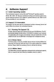
... is enabled in the Support CD to activate the devices. 4.2.3 Utilities Menu The Utilities Menu shows the applications software that enhance the motherboard features. 4.2.1 Running The Support CD To begin using the support CD, insert the CD into your CD-ROM drive. Please install ... display the menus. 4.2.2 Drivers Menu The Drivers Menu shows the available devices drivers including ASRock Express GbL PCI Express LAN card driver if the system detects the installed devices. Because motherboard settings and hardware options vary, use the setup procedures in this chapter for more information....
... is enabled in the Support CD to activate the devices. 4.2.3 Utilities Menu The Utilities Menu shows the applications software that enhance the motherboard features. 4.2.1 Running The Support CD To begin using the support CD, insert the CD into your CD-ROM drive. Please install ... display the menus. 4.2.2 Drivers Menu The Drivers Menu shows the available devices drivers including ASRock Express GbL PCI Express LAN card driver if the system detects the installed devices. Because motherboard settings and hardware options vary, use the setup procedures in this chapter for more information....

