
User Manual
Page 3
Introduction 5 1.1 Package Contents 5 1.2 Specifications 6 1.3 Motherboard Layout 9 1.4 ASRock 8CH I/O 10 2. BIOS SETUP UTILITY 21 3.1 Introduction 21 3.1.1 BIOS Menu Bar 21 3.1.2 Navigation Keys 22 3.2 Main Screen 22 3.3 Advanced Screen 23 3.3.1 CPU Configuration 24 3.3.2 Chipset Configuration 26 3.3.3 ACPI Configuration 27 3.3.4 IDE Configuration 28 3.3.5 PCIPnP ...
Introduction 5 1.1 Package Contents 5 1.2 Specifications 6 1.3 Motherboard Layout 9 1.4 ASRock 8CH I/O 10 2. BIOS SETUP UTILITY 21 3.1 Introduction 21 3.1.1 BIOS Menu Bar 21 3.1.2 Navigation Keys 22 3.2 Main Screen 22 3.3 Advanced Screen 23 3.3.1 CPU Configuration 24 3.3.2 Chipset Configuration 26 3.3.3 ACPI Configuration 27 3.3.4 IDE Configuration 28 3.3.5 PCIPnP ...
User Manual
Page 5
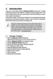
... conforming to ASRock's commitment to BIOS setup and information of the motherboard and step-bystep guide to change without further notice. Chapter 3 and 4 contain the configuration guide to quality and endurance. ASRock website http://www.asrock.com 1.1 Package Contents 1 x ASRock K8Upgrade-760GX Motherboard (Micro ATX Form Factor: 9.0-in x 9.6-in, 22.9 cm x 24.4 cm) 1 x ASRock K8Upgrade-760GX Quick Installation Guide 1 x ASRock K8Upgrade-760GX Support...
... conforming to ASRock's commitment to BIOS setup and information of the motherboard and step-bystep guide to change without further notice. Chapter 3 and 4 contain the configuration guide to quality and endurance. ASRock website http://www.asrock.com 1.1 Package Contents 1 x ASRock K8Upgrade-760GX Motherboard (Micro ATX Form Factor: 9.0-in x 9.6-in, 22.9 cm x 24.4 cm) 1 x ASRock K8Upgrade-760GX Quick Installation Guide 1 x ASRock K8Upgrade-760GX Support...

User Manual
Page 7
... the power cord, then plug it is not recommended to perform over-clocking. For power-saving sake, it is detected, the system will automatically shutdown. ASRock I/O PlusTM: 1 PS/2 Mouse Port, 1 PS/2 Keyboard Port 1 VGA Port 1 Parallel Port (ECP/EPP Support) 6 Ready-to-Use USB 2.0 Ports... 1 RJ-45 Port Audio Jack: Line In / Line Out / Microphone COM Port: 1 COM Port Header to support a COM port module BIOS: AMI Legal BIOS Supports "Plug and Play" ACPI 1.1 Compliance Wake Up Events SMBIOS 2.3.1 Support CPU Frequency Stepless Control (only for USB 2.0 works fine under Microsoft...
... the power cord, then plug it is not recommended to perform over-clocking. For power-saving sake, it is detected, the system will automatically shutdown. ASRock I/O PlusTM: 1 PS/2 Mouse Port, 1 PS/2 Keyboard Port 1 VGA Port 1 Parallel Port (ECP/EPP Support) 6 Ready-to-Use USB 2.0 Ports... 1 RJ-45 Port Audio Jack: Line In / Line Out / Microphone COM Port: 1 COM Port Header to support a COM port module BIOS: AMI Legal BIOS Supports "Plug and Play" ACPI 1.1 Compliance Wake Up Events SMBIOS 2.3.1 Support CPU Frequency Stepless Control (only for USB 2.0 works fine under Microsoft...

User Manual
Page 8
... Motherboard Layout PS2 Keyboard 12 3 PS2_USB_PW1 PS2 1 Mouse CPU_FAN1 ATX12V1 4 56 7 22.9cm (9.0-in) 89 J15 1 IR1 1 2Mb BIOS Super I/O PARALLEL PORT ATXPWR1 DDR400 DDR2 (64/72 bit, 184-pin module) DDR1 (64/72 bit, 184-pin module) SOCKET 754 ...-45 Shared 1 USB 2.0 T: USB4 B: USB5 USB45 CD1 1 1 J7 J8 FSB800 1 1 J5 J6 1 1 J3 J4 SiS 760GX Chipset 5.1CH 1 1 J1 J2 AUDIO1 1 JR1 JL1 AUX1 FUTURE_CPU_PORT1 1 J9 1 J10 K8Upgrade-760GX 1.5V_AGP1 LAN PHY PCI 1 AGP 8X AUDIO CODEC AMR1 PCI 2 1 COM1 CMOS Battery CLRCMOS2 1 USB2.0 FLOPPY1 IDE2 IDE1 SiS 964...
... Motherboard Layout PS2 Keyboard 12 3 PS2_USB_PW1 PS2 1 Mouse CPU_FAN1 ATX12V1 4 56 7 22.9cm (9.0-in) 89 J15 1 IR1 1 2Mb BIOS Super I/O PARALLEL PORT ATXPWR1 DDR400 DDR2 (64/72 bit, 184-pin module) DDR1 (64/72 bit, 184-pin module) SOCKET 754 ...-45 Shared 1 USB 2.0 T: USB4 B: USB5 USB45 CD1 1 1 J7 J8 FSB800 1 1 J5 J6 1 1 J3 J4 SiS 760GX Chipset 5.1CH 1 1 J1 J2 AUDIO1 1 JR1 JL1 AUX1 FUTURE_CPU_PORT1 1 J9 1 J10 K8Upgrade-760GX 1.5V_AGP1 LAN PHY PCI 1 AGP 8X AUDIO CODEC AMR1 PCI 2 1 COM1 CMOS Battery CLRCMOS2 1 USB2.0 FLOPPY1 IDE2 IDE1 SiS 964...
User Manual
Page 15
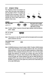
... illustration shows a 3-pin jumper whose pin1 and pin2 are "Short" when jumper cap is "Short". Note: To select +5VSB, it down before you update the BIOS. JR1 / JL1 Jumper (see p.8, No. 1) +5V +5VSB +5VSB (standby) for 5 seconds. However, please do not clear the CMOS right after you do the clear-CMOS... placed on these 2 pins. The data in CMOS. To clear and reset the system parameters to clear the CMOS when you just finish updating the BIOS, you must boot up events. After waiting for 15 seconds, use a jumper cap to short the Clear CMOS jumper for PS/2 or USB wake up...
... illustration shows a 3-pin jumper whose pin1 and pin2 are "Short" when jumper cap is "Short". Note: To select +5VSB, it down before you update the BIOS. JR1 / JL1 Jumper (see p.8, No. 1) +5V +5VSB +5VSB (standby) for 5 seconds. However, please do not clear the CMOS right after you do the clear-CMOS... placed on these 2 pins. The data in CMOS. To clear and reset the system parameters to clear the CMOS when you just finish updating the BIOS, you must boot up events. After waiting for 15 seconds, use a jumper cap to short the Clear CMOS jumper for PS/2 or USB wake up...

User Manual
Page 19
... the Support CD at the following path: ..\ RAID BIOS Setting Utility 19 This section will guide you use Hot Plug function. WARNING! STEP 3: Connect one end of the SATA data cable to the SATA hard disk. 2.8 Hot Plug Function for SATA HDDs K8Upgrade-760GX motherboard supports Hot Plug function for the action to...
... the Support CD at the following path: ..\ RAID BIOS Setting Utility 19 This section will guide you use Hot Plug function. WARNING! STEP 3: Connect one end of the SATA data cable to the SATA hard disk. 2.8 Hot Plug Function for SATA HDDs K8Upgrade-760GX motherboard supports Hot Plug function for the action to...

User Manual
Page 20
... document in the Support CD, "Guide to SiS RAID Utility for Windows", which is located in the folder at the following path: .. \ RAID BIOS Setting Utility You may also set RAID 0 / RAID 1 configuration before you start to configure the RAID function, you need to make an SATA driver...OS installation. STEP 4: Then you will need to check the installation guide in the Support CD for Windows" in Windows environment. STEP 1: Insert the ASRock Support CD into the floppy drive, and press . Please insert a floppy diskette into your optical drive to boot your system. Please refer to the...
... document in the Support CD, "Guide to SiS RAID Utility for Windows", which is located in the folder at the following path: .. \ RAID BIOS Setting Utility You may also set RAID 0 / RAID 1 configuration before you start to configure the RAID function, you need to make an SATA driver...OS installation. STEP 4: Then you will need to check the installation guide in the Support CD for Windows" in Windows environment. STEP 1: Insert the ASRock Support CD into the floppy drive, and press . Please insert a floppy diskette into your optical drive to boot your system. Please refer to the...

User Manual
Page 21
... screens and descriptions are for reference purpose only, and they may run the BIOS SETUP UTILITY when you see on your system. BIOS SETUP UTILITY 3.1 Introduction This section explains how to use the BIOS SETUP UTILITY to configure your screen. 3.1.1 BIOS Menu Bar The top of the screen has a menu bar with its test... routines. Please press during the Power-On-Self-Test (POST) to get into the sub screen. 21 If you wish to enter the BIOS SETUP UTILITY after POST, restart the system by pressing + + , or by turning the system off and then back on the motherboard stores the...
... screens and descriptions are for reference purpose only, and they may run the BIOS SETUP UTILITY when you see on your system. BIOS SETUP UTILITY 3.1 Introduction This section explains how to use the BIOS SETUP UTILITY to configure your screen. 3.1.1 BIOS Menu Bar The top of the screen has a menu bar with its test... routines. Please press during the Power-On-Self-Test (POST) to get into the sub screen. 21 If you wish to enter the BIOS SETUP UTILITY after POST, restart the system by pressing + + , or by turning the system off and then back on the motherboard stores the...

User Manual
Page 22
... Main Advanced H/W Monitor Boot Security Exit System Overview System Time System Date [17:00:09] [Thu 07/29/2004] BIOS Version : K8Upgrade-760GX BIOS P1.0 Processor Type : AMD Athlon(tm) 64 Processor 3400+ Processor Speed : 2200 MHz L1 Cache Size : 128KB L2 Cache Size : 1024KB Total Memory DDR 1 DDR 2 : ... for the function description of each navigation key. 3.1.2 Navigation Keys Please check the following table for all the settings To save changes and exit the BIOS SETUP UTILITY To jump to the Exit Screen or exit the current screen 3.2 Main Screen When you enter the...
... Main Advanced H/W Monitor Boot Security Exit System Overview System Time System Date [17:00:09] [Thu 07/29/2004] BIOS Version : K8Upgrade-760GX BIOS P1.0 Processor Type : AMD Athlon(tm) 64 Processor 3400+ Processor Speed : 2200 MHz L1 Cache Size : 128KB L2 Cache Size : 1024KB Total Memory DDR 1 DDR 2 : ... for the function description of each navigation key. 3.1.2 Navigation Keys Please check the following table for all the settings To save changes and exit the BIOS SETUP UTILITY To jump to the Exit Screen or exit the current screen 3.2 Main Screen When you enter the...

User Manual
Page 23
...you will see the below sections may cause system to malfunction. Setting wrong values in below Main screen when entering the BIOS SETUP UTILITY. Main BIOS SETUP UTILITY Advanced H/W Monitor Boot Security Exit Advanced Settings WARNING : Setting wrong values in this section may cause the ...system to malfunction. 23 If ASRock 939CPU Board is installed into the FUTURE_CPU_PORT on this motherboard, you may set the configurations for ...
...you will see the below sections may cause system to malfunction. Setting wrong values in below Main screen when entering the BIOS SETUP UTILITY. Main BIOS SETUP UTILITY Advanced H/W Monitor Boot Security Exit Advanced Settings WARNING : Setting wrong values in this section may cause the ...system to malfunction. 23 If ASRock 939CPU Board is installed into the FUTURE_CPU_PORT on this motherboard, you may set the configurations for ...

User Manual
Page 24
... American Megatrends, Inc. 24 The actual CPU host frequency will be [Disabled] for system stability. 3.3.1 CPU Configuration BIOS SETUP UTILITY Advanced CPU Configuration CPU Host Frequency Actual Frequency (MHz) Spread Spectrum Cool' n' Quiet Processor Maximum Multiplier ...V [Auto] [Auto] [Disabled] [Auto] [8 Beats] [Auto] [Auto] [Auto] [Auto] Select how to [Auto] by default. BIOS SETUP UTILITY Advanced CPU Configuration CPU Host Frequency Actual Frequency (MHz) Spread Spectrum Cool' n' Quiet Processor Maximum Multiplier Processor Maximum Voltage Multiplier/Voltage Change Processor...
... American Megatrends, Inc. 24 The actual CPU host frequency will be [Disabled] for system stability. 3.3.1 CPU Configuration BIOS SETUP UTILITY Advanced CPU Configuration CPU Host Frequency Actual Frequency (MHz) Spread Spectrum Cool' n' Quiet Processor Maximum Multiplier ...V [Auto] [Auto] [Disabled] [Auto] [8 Beats] [Auto] [Auto] [Auto] [Auto] Select how to [Auto] by default. BIOS SETUP UTILITY Advanced CPU Configuration CPU Host Frequency Actual Frequency (MHz) Spread Spectrum Cool' n' Quiet Processor Maximum Multiplier Processor Maximum Voltage Multiplier/Voltage Change Processor...

User Manual
Page 25
... is not recommended to a value higher than the value of this item. otherwise, it will be hidden. You may set by the code using [Auto]. BIOS SETUP UTILITY Advanced Cool' n' Quiet Processor Maximum Multiplier Processor Maximum Voltage Multiplier/Voltage Change Processor Multiplier Processor Voltage Memory Clock Flexibility Option Bank Interleaving Burst...
... is not recommended to a value higher than the value of this item. otherwise, it will be hidden. You may set by the code using [Auto]. BIOS SETUP UTILITY Advanced Cool' n' Quiet Processor Maximum Multiplier Processor Maximum Voltage Multiplier/Voltage Change Processor Multiplier Processor Voltage Memory Clock Flexibility Option Bank Interleaving Burst...

User Manual
Page 26
... options: [2T], [1T]. For an AGP 2.0 card, you may set AGP Data Rate between [8X] or [4X], and the default value is [2T]. 3.3.2 Chipset Configuration BIOS SETUP UTILITY Advanced Chipset Settings OnBoard AC97 Audio OnBoard LAN [Auto] [Enabled] AGP Aperture Size AGP Data Rate AGP Fast Write Primary Graphics Adapter [64...
... options: [2T], [1T]. For an AGP 2.0 card, you may set AGP Data Rate between [8X] or [4X], and the default value is [2T]. 3.3.2 Chipset Configuration BIOS SETUP UTILITY Advanced Chipset Settings OnBoard AC97 Audio OnBoard LAN [Auto] [Enabled] AGP Aperture Size AGP Data Rate AGP Fast Write Primary Graphics Adapter [64...

User Manual
Page 27
... allows you may set the power state after an unexpected AC/Power loss. HT Speed For both 754-Pin CPU and 939-Pin CPU (if ASRock 939CPU Board is installed into the FUTURE_CPU_PORT on this motherboard), you to set the HyperTransport width as [8 bit], [16 bit] or [Auto]. Suspend to...] is [Auto]. Select [Auto] will switch the PCI Bus scanning order while searching for video card. If [Power On] is [Auto]. 3.3.3 ACPI Configuration Advanced BIOS SETUP UTILITY ACPI Settings Suspend To RAM Repost Video on STR Resume Restore on AC/Power Loss" will be hidden. If you may use this...
... allows you may set the power state after an unexpected AC/Power loss. HT Speed For both 754-Pin CPU and 939-Pin CPU (if ASRock 939CPU Board is installed into the FUTURE_CPU_PORT on this motherboard), you to set the HyperTransport width as [8 bit], [16 bit] or [Auto]. Suspend to...] is [Auto]. Select [Auto] will switch the PCI Bus scanning order while searching for video card. If [Power On] is [Auto]. 3.3.3 ACPI Configuration Advanced BIOS SETUP UTILITY ACPI Settings Suspend To RAM Repost Video on STR Resume Restore on AC/Power Loss" will be hidden. If you may use this...

User Manual
Page 28
... turn on the system from the power-soft-off mode. RTC Alarm Power On Use this item to power on the system. 3.3.4 IDE Configuration Advanced BIOS SETUP UTILITY IDE Configuration OnBoard IDE Controller OnBoard SATA Controller Primary IDE Master Primary IDE Slave Secondary IDE Master Secondary IDE Slave [Both] [Enabled] [Hard...
... turn on the system from the power-soft-off mode. RTC Alarm Power On Use this item to power on the system. 3.3.4 IDE Configuration Advanced BIOS SETUP UTILITY IDE Configuration OnBoard IDE Controller OnBoard SATA Controller Primary IDE Master Primary IDE Slave Secondary IDE Master Secondary IDE Slave [Both] [Enabled] [Hard...

User Manual
Page 29
... MO. This is enabled, it will enhance hard disk performance by optimizing the hard disk timing. After selecting the hard disk information into BIOS, use of device connected to the system. +F1 F9 F10 ESC Select Screen Select Item Change Option General Help Load Defaults Save and Exit... Exit v02.54 (C) Copyright 1985-2003, American Megatrends, Inc. for a hard disk > 512 MB under DOS and Windows; BIOS SETUP UTILITY Advanced Primary IDE Master Device Vendor Size LBA Mode Block Mode PIO Mode Async DMA Ultra DMA S.M.A.R.T. :Hard Disk :MAXTOR 6L080J4 :80.0 ...
... MO. This is enabled, it will enhance hard disk performance by optimizing the hard disk timing. After selecting the hard disk information into BIOS, use of device connected to the system. +F1 F9 F10 ESC Select Screen Select Item Change Option General Help Load Defaults Save and Exit... Exit v02.54 (C) Copyright 1985-2003, American Megatrends, Inc. for a hard disk > 512 MB under DOS and Windows; BIOS SETUP UTILITY Advanced Primary IDE Master Device Vendor Size LBA Mode Block Mode PIO Mode Async DMA Ultra DMA S.M.A.R.T. :Hard Disk :MAXTOR 6L080J4 :80.0 ...

User Manual
Page 30
... in this item to malfunction. Use this item to enable 32-bit access to maximize the IDE hard disk data transfer rate. 3.3.5 PCIPnP Configuration Advanced BIOS SETUP UTILITY Advanced PCI / PnP Settings WARNING: Setting wrong values in units of PCI clocks for PCI device latency timer register. PCI Latency Timer The...
... in this item to malfunction. Use this item to enable 32-bit access to maximize the IDE hard disk data transfer rate. 3.3.5 PCIPnP Configuration Advanced BIOS SETUP UTILITY Advanced PCI / PnP Settings WARNING: Setting wrong values in units of PCI clocks for PCI device latency timer register. PCI Latency Timer The...

User Manual
Page 31
...Option General Help Load Defaults Save and Exit Exit v02.54 (C) Copyright 1985-2003, American Megatrends, Inc. 3.3.7 Super IO Configuration BIOS SETUP UTILITY Advanced Configure Super IO Chipset OnBoard Floppy Controller Serial Port Address Infrared Port Address Parallel Port Address Parallel Port Mode EPP... Game Port OnBoard MIDI Port [Enabled] [3F8 / IRQ4] [Disabled] [378] [ECP + EPP] [1.9] [DMA3] [IRQ7] [Enabled] [Disabled] Allow BIOS to Enable or Disable Floppy Controller. +F1 F9 F10 ESC Select Screen Select Item Change Option General Help Load Defaults Save and Exit Exit v02...
...Option General Help Load Defaults Save and Exit Exit v02.54 (C) Copyright 1985-2003, American Megatrends, Inc. 3.3.7 Super IO Configuration BIOS SETUP UTILITY Advanced Configure Super IO Chipset OnBoard Floppy Controller Serial Port Address Infrared Port Address Parallel Port Address Parallel Port Mode EPP... Game Port OnBoard MIDI Port [Enabled] [3F8 / IRQ4] [Disabled] [378] [ECP + EPP] [1.9] [DMA3] [IRQ7] [Enabled] [Disabled] Allow BIOS to Enable or Disable Floppy Controller. +F1 F9 F10 ESC Select Screen Select Item Change Option General Help Load Defaults Save and Exit Exit v02...

User Manual
Page 33
...or disable the use of the CPU temperature, motherboard temperature, CPU fan speed, chassis fan speed, and the critical voltage. Main Advanced BIOS SETUP UTILITY H/W Monitor Boot Security Exit Hardware Health Event Monitoring CPU Temperature M / B Temperature CPU Fan Speed Chassis Fan Speed Vcore +... Help Load Defaults Save and Exit Exit v02.54 (C) Copyright 1985-2003, American Megatrends, Inc. 33 etc. 3.3.8 USB Configuration BIOS SETUP UTILITY Advanced USB Configuration USB Controller USB 2.0 Support Legacy USB Support [Enabled] [Enabled] [Disabled] To enable or disable ...
...or disable the use of the CPU temperature, motherboard temperature, CPU fan speed, chassis fan speed, and the critical voltage. Main Advanced BIOS SETUP UTILITY H/W Monitor Boot Security Exit Hardware Health Event Monitoring CPU Temperature M / B Temperature CPU Fan Speed Chassis Fan Speed Vcore +... Help Load Defaults Save and Exit Exit v02.54 (C) Copyright 1985-2003, American Megatrends, Inc. 33 etc. 3.3.8 USB Configuration BIOS SETUP UTILITY Advanced USB Configuration USB Controller USB 2.0 Support Legacy USB Support [Enabled] [Enabled] [Disabled] To enable or disable ...

User Manual
Page 34
...Help F9 Load Defaults F10 Save and Exit ESC Exit v02.54 (C) Copyright 1985-2003, American Megatrends, Inc. 3.5.1 Boot Settings Configuration BIOS SETUP UTILITY Boot Boot Settings Configuration Boot From Network Bootup Num-Lock [Disabled] [On] To enable or disable the boot from network ...-2003, American Megatrends, Inc. Select Screen Select Item Enter Go to enable or disable the Boot From Network feature. Main Advanced BIOS SETUP UTILITY H/W Monitor Boot Security Exit Boot Settings Boot Settings Configuration Boot Device Priority Hard Disk Drives Removable Drives CD/DVD Drives ...
...Help F9 Load Defaults F10 Save and Exit ESC Exit v02.54 (C) Copyright 1985-2003, American Megatrends, Inc. 3.5.1 Boot Settings Configuration BIOS SETUP UTILITY Boot Boot Settings Configuration Boot From Network Bootup Num-Lock [Disabled] [On] To enable or disable the boot from network ...-2003, American Megatrends, Inc. Select Screen Select Item Enter Go to enable or disable the Boot From Network feature. Main Advanced BIOS SETUP UTILITY H/W Monitor Boot Security Exit Boot Settings Boot Settings Configuration Boot Device Priority Hard Disk Drives Removable Drives CD/DVD Drives ...


