RAID Installation Guide
Page 1
Guide to SATA Hard Disks Installation 2 1.1 Serial ATA (SATA) Hard Disks Installation 2 1.2 Making a SATA Driver Diskette 3 2. Guide to SATA Hard Disks Installation and RAID Configuration 1. Guide to RAID Configurations 4 2.1 Introduction of RAID 4 2.2 RAID Configuration Precautions 6 2.3 BIOS Configuration Utility 7 2.3.1 Enter BIOS Configuration Utility 7 2.3.2 Create Disk Array 8 1
Guide to SATA Hard Disks Installation 2 1.1 Serial ATA (SATA) Hard Disks Installation 2 1.2 Making a SATA Driver Diskette 3 2. Guide to SATA Hard Disks Installation and RAID Configuration 1. Guide to RAID Configurations 4 2.1 Introduction of RAID 4 2.2 RAID Configuration Precautions 6 2.3 BIOS Configuration Utility 7 2.3.1 Enter BIOS Configuration Utility 7 2.3.2 Create Disk Array 8 1
RAID Installation Guide
Page 3
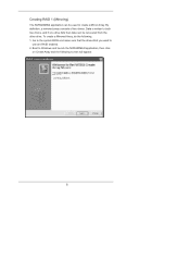
... for boot devices selection appears. STEP 5: The system will need to generate Serial ATA driver diskette [YN]?", press . STEP 4: Then you start to use "RAID BIOS Setting Utility" in the section 2.3 to make a SATA driver diskette. You may start the OS installation. Formatting the floppy diskette will see the message on...
... for boot devices selection appears. STEP 5: The system will need to generate Serial ATA driver diskette [YN]?", press . STEP 4: Then you start to use "RAID BIOS Setting Utility" in the section 2.3 to make a SATA driver diskette. You may start the OS installation. Formatting the floppy diskette will see the message on...
RAID Installation Guide
Page 7
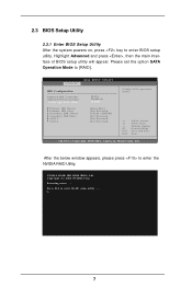
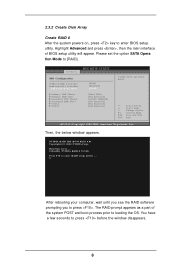
...window appears, please press to [RAID]. Highlight Advanced and press , then the main interface of BIOS setup utility will appear. American Megatrends, Inc. Press F10 to enter BIOS setup utility. Advanced BIOS SETUP UTILITY IDE Configuration OnBoard IDE Controller OnBoard SATA Controller SATA Operation Mode Primary IDE Master Primary ...F1 F10 ESC Select Screen Select Item Change Option General Help Save and Exit Exit v02.53 (C) Copyright 1985-2004. 2.3 BIOS Setup Utility 2.3.1 Enter BIOS Setup Utility After the system powers on, press key to enter RAID setup utility . . . 7
...window appears, please press to [RAID]. Highlight Advanced and press , then the main interface of BIOS setup utility will appear. American Megatrends, Inc. Press F10 to enter BIOS setup utility. Advanced BIOS SETUP UTILITY IDE Configuration OnBoard IDE Controller OnBoard SATA Controller SATA Operation Mode Primary IDE Master Primary ...F1 F10 ESC Select Screen Select Item Change Option General Help Save and Exit Exit v02.53 (C) Copyright 1985-2004. 2.3 BIOS Setup Utility 2.3.1 Enter BIOS Setup Utility After the system powers on, press key to enter RAID setup utility . . . 7
RAID Installation Guide
Page 8
... General Help Save and Exit Exit v02.53 (C) Copyright 1985-2004. The RAID prompt appears as a part of BIOS setup utility will appear. You have a few seconds to enter BIOS setup utility. 2.3.2 Create Disk Array Create RAID 0 After the system powers on, press key to press before the... window disappears. 8 NVIDIA RAID IDE ROM BIOS 4.81 Copyright (C) 2004 NVIDIA Corp. Please set the option SATA Opera tion Mode to enter RAID setup utility . . . Highlight Advanced and press ,...
... General Help Save and Exit Exit v02.53 (C) Copyright 1985-2004. The RAID prompt appears as a part of BIOS setup utility will appear. You have a few seconds to enter BIOS setup utility. 2.3.2 Create Disk Array Create RAID 0 After the system powers on, press key to press before the... window disappears. 8 NVIDIA RAID IDE ROM BIOS 4.81 Copyright (C) 2004 NVIDIA Corp. Please set the option SATA Opera tion Mode to enter RAID setup utility . . . Highlight Advanced and press ,...

RAID Installation Guide
Page 10
NVIDIA RAID Utility Jan 12 2005 - These are available for use as RAID array disk, 1. Move it from the RAID Config BIOS setup page appear in kilobytes, and affect how data is arranged on the disk. The disks that you enabled from the Free Disks block to ...
NVIDIA RAID Utility Jan 12 2005 - These are available for use as RAID array disk, 1. Move it from the RAID Config BIOS setup page appear in kilobytes, and affect how data is arranged on the disk. The disks that you enabled from the Free Disks block to ...
RAID Installation Guide
Page 12
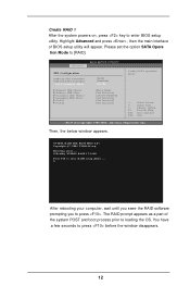
... 1 74.54G Press F10 to press before the window disappears. 12 You have a few seconds to enter RAID setup utility . . . NVIDIA RAID IDE ROM BIOS 4.81 Copyright (C) 2004 NVIDIA Corp. After rebooting your computer, wait until you seee the RAID software prompting you to enter...Megatrends, Inc. Create RAID 1 After the system powers on, press key to press . Then, the below window appears. The RAID prompt appears as a part of BIOS setup utility will appear. Please set the option SATA Opera tion Mode to loading the OS. Highlight Advanced and press , then the main interface of...
... 1 74.54G Press F10 to press before the window disappears. 12 You have a few seconds to enter RAID setup utility . . . NVIDIA RAID IDE ROM BIOS 4.81 Copyright (C) 2004 NVIDIA Corp. After rebooting your computer, wait until you seee the RAID software prompting you to enter...Megatrends, Inc. Create RAID 1 After the system powers on, press key to press . Then, the below window appears. The RAID prompt appears as a part of BIOS setup utility will appear. Please set the option SATA Opera tion Mode to loading the OS. Highlight Advanced and press , then the main interface of...
RAID Installation Guide
Page 15
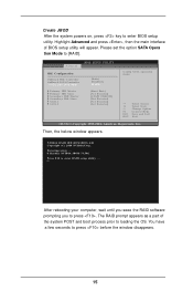
...prompting you to enter RAID setup utility . . . Then, the below window appears. You have a few seconds to enter BIOS setup utility. NVIDIA RAID IDE ROM BIOS 4.81 Copyright (C) 2004 NVIDIA Corp. Create JBOD After the system powers on, press key to press before the window disappears.... 15 Highlight Advanced and press , then the main interface of the system POST and boot process prior to [RAID]. Advanced BIOS SETUP UTILITY IDE Configuration OnBoard IDE Controller OnBoard SATA Controller SATA Operation Mode Primary IDE Master Primary IDE Slave Secondary IDE Master Secondary...
...prompting you to enter RAID setup utility . . . Then, the below window appears. You have a few seconds to enter BIOS setup utility. NVIDIA RAID IDE ROM BIOS 4.81 Copyright (C) 2004 NVIDIA Corp. Create JBOD After the system powers on, press key to press before the window disappears.... 15 Highlight Advanced and press , then the main interface of the system POST and boot process prior to [RAID]. Advanced BIOS SETUP UTILITY IDE Configuration OnBoard IDE Controller OnBoard SATA Controller SATA Operation Mode Primary IDE Master Primary IDE Slave Secondary IDE Master Secondary...
RAID Utility for Windows Guide
Page 2
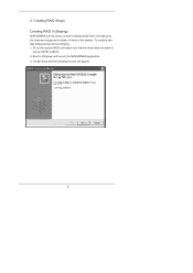
Go to the system BIOS and make sure that the drives that you want to Windows and launch the NVRAIDMAN application. 3. Boot to use are RAID enabled. 2. Create Array and the following . 1. 2. Creating RAID Arrays Creating RAID 0 (Striping) NVRAIDMAN can be used to create a striped array from one disk up to the maximum supported number of disks in the system. To create a twodisk Striped Array do the following screen will appear. 2
Go to the system BIOS and make sure that the drives that you want to Windows and launch the NVRAIDMAN application. 3. Boot to use are RAID enabled. 2. Create Array and the following . 1. 2. Creating RAID Arrays Creating RAID 0 (Striping) NVRAIDMAN can be used to create a striped array from one disk up to the maximum supported number of disks in the system. To create a twodisk Striped Array do the following screen will appear. 2
RAID Utility for Windows Guide
Page 6
Boot to Windows and launch the NVRAIDMAN application, then click on Create Array and the following . 1. Data is written to both two drives, and if one drive fails then data can be recovered from the other drive. Go to the system BIOS and make sure that the drives that you want to use are RAID enabled. 2. To create a Mirrored Array, do the following screen will appear. 6 Creating RAID 1 (Mirroring) The NVRAIDMAN application can be used to create a Mirror Array. By definition, a mirrored array consists of two drives.
Boot to Windows and launch the NVRAIDMAN application, then click on Create Array and the following . 1. Data is written to both two drives, and if one drive fails then data can be recovered from the other drive. Go to the system BIOS and make sure that the drives that you want to use are RAID enabled. 2. To create a Mirrored Array, do the following screen will appear. 6 Creating RAID 1 (Mirroring) The NVRAIDMAN application can be used to create a Mirror Array. By definition, a mirrored array consists of two drives.

RAID Utility for Windows Guide
Page 10
Boot to Windows and launch the NVRAIDMAN application, then click on Create Array and the following screen will appear. 10 To create a Spanning Array do the following screen will appear. 3. Go to the system BIOS and make sure that the drives that you want to start such an array. Click Next and the following : 1. Creating JBOD (Spanning) NVRAIDMAN can be used to create a Spanning Array which requires at least one disk to use are RAID enabled. 2.
Boot to Windows and launch the NVRAIDMAN application, then click on Create Array and the following screen will appear. 10 To create a Spanning Array do the following screen will appear. 3. Go to the system BIOS and make sure that the drives that you want to start such an array. Click Next and the following : 1. Creating JBOD (Spanning) NVRAIDMAN can be used to create a Spanning Array which requires at least one disk to use are RAID enabled. 2.

User Manual
Page 3
... 24 3.1 Introduction 24 3.1.1 BIOS Menu Bar 24 3.1.2 Navigation Keys 25 3.2 Main Screen 25 3.3 Advanced Screen 26 3.3.1 CPU Configuration 26 3.3.2 Chipset Configuration 29 3.3.3 ACPI Configuration 30 3.3.4 IDE Configuration 31 3.3.5 PCIPnP ...
... 24 3.1 Introduction 24 3.1.1 BIOS Menu Bar 24 3.1.2 Navigation Keys 25 3.2 Main Screen 25 3.3 Advanced Screen 26 3.3.1 CPU Configuration 26 3.3.2 Chipset Configuration 29 3.3.3 ACPI Configuration 30 3.3.4 IDE Configuration 31 3.3.5 PCIPnP ...

User Manual
Page 5
... (Micro ATX Form Factor: 9.6-in x 8.0-in, 24.4 cm x 20.3 cm) 1 x ASRock K8NF4G-VSTA Quick Installation Guide 1 x ASRock K8NF4G-VSTA Support CD 1 x Ultra ATA 66/100/133 IDE Ribbon Cable (80-conductor) 1 x 3.5-in Floppy Drive Ribbon Cable 1 x Serial ... manual occur, the updated version will be available on ASRock website as well. Introduction Thank you for purchasing ASRock K8NF4G-VSTA motherboard, a reliable motherboard produced under ASRock's consistently stringent quality control. Because the motherboard specifications and the BIOS software might be updated, the content of this manual,...
... (Micro ATX Form Factor: 9.6-in x 8.0-in, 24.4 cm x 20.3 cm) 1 x ASRock K8NF4G-VSTA Quick Installation Guide 1 x ASRock K8NF4G-VSTA Support CD 1 x Ultra ATA 66/100/133 IDE Ribbon Cable (80-conductor) 1 x 3.5-in Floppy Drive Ribbon Cable 1 x Serial ... manual occur, the updated version will be available on ASRock website as well. Introduction Thank you for purchasing ASRock K8NF4G-VSTA motherboard, a reliable motherboard produced under ASRock's consistently stringent quality control. Because the motherboard specifications and the BIOS software might be updated, the content of this manual,...
User Manual
Page 7
... compliant (see CAUTION 6) - 2 x ATA133 IDE connectors (support 4 x IDE devices) - 1 x Floppy connector - 1 x IR header - 1 x Game header - 1 x COM port header - Connector BIOS Feature Support CD Hardware Monitor OS Certifications - 2 x Serial ATAII 3.0Gb/s connectors, support RAID 0, 1, JBOD (No support for "Hot Plug" function) (see CAUTION 8) - CPU Temperature Sensing...- 4 pin 12V power connector - Front panel audio connector - 2 x USB 2.0 headers (support 4 USB 2.0 ports) (see CAUTION 7) - 4Mb AMI BIOS - Supports jumperfree - CPU Overheat Shutdown to Protect CPU Life -
... compliant (see CAUTION 6) - 2 x ATA133 IDE connectors (support 4 x IDE devices) - 1 x Floppy connector - 1 x IR header - 1 x Game header - 1 x COM port header - Connector BIOS Feature Support CD Hardware Monitor OS Certifications - 2 x Serial ATAII 3.0Gb/s connectors, support RAID 0, 1, JBOD (No support for "Hot Plug" function) (see CAUTION 8) - CPU Temperature Sensing...- 4 pin 12V power connector - Front panel audio connector - 2 x USB 2.0 headers (support 4 USB 2.0 ports) (see CAUTION 7) - 4Mb AMI BIOS - Supports jumperfree - CPU Overheat Shutdown to Protect CPU Life -
User Manual
Page 15
... will disable onboard VGA function when installing VGA card. Step 5. Installing an expansion card Step 1. With the internal onboard VGA and the external add-on K8NF4G-VSTA motherboard. Remove the bracket facing the slot that you start the installation. PCI Slots: PCI slots are 2 PCI Express slots, 2 PCI slots and 1 HDMR ...enter the option "Share Memory" of "Share Memory" is used to [16MB], [32MB], [64MB], or [128MB]. The HDMR slot is unplugged. The default value of BIOS to adjust the memory capability to insert an ASRock HDMR card with x16 lane width graphics cards.
... will disable onboard VGA function when installing VGA card. Step 5. Installing an expansion card Step 1. With the internal onboard VGA and the external add-on K8NF4G-VSTA motherboard. Remove the bracket facing the slot that you start the installation. PCI Slots: PCI slots are 2 PCI Express slots, 2 PCI slots and 1 HDMR ...enter the option "Share Memory" of "Share Memory" is used to [16MB], [32MB], [64MB], or [128MB]. The HDMR slot is unplugged. The default value of BIOS to adjust the memory capability to insert an ASRock HDMR card with x16 lane width graphics cards.
User Manual
Page 16
...Note: To select +5VSB, it down before you must boot up events. If you need to clear the CMOS when you just finish updating the BIOS, you do not clear the CMOS right after you to clear the data in CMOS includes system setup information such as system password, date, time...) (see p.9 No. 20) Pin1 FLOPPY1 the red-striped side to enable (see p.9, No. 11) 1_2 2_3 Default Clear CMOS Note: CLRCMOS2 allows you update the BIOS. Clear CMOS Jumper (CLRCMOS2) (see p.9, No. 1) +5V +5VSB +5VSB (standby) for 5 seconds. To clear and reset the system parameters to short pin2 and ...
...Note: To select +5VSB, it down before you must boot up events. If you need to clear the CMOS when you just finish updating the BIOS, you do not clear the CMOS right after you to clear the data in CMOS includes system setup information such as system password, date, time...) (see p.9 No. 20) Pin1 FLOPPY1 the red-striped side to enable (see p.9, No. 11) 1_2 2_3 Default Clear CMOS Note: CLRCMOS2 allows you update the BIOS. Clear CMOS Jumper (CLRCMOS2) (see p.9, No. 1) +5V +5VSB +5VSB (standby) for 5 seconds. To clear and reset the system parameters to short pin2 and ...

User Manual
Page 18
...) USB_PWR P-5 P+5 GND DUMMY 1 GND P+4 P-4 USB_PWR HD 8CH I /O", select "Connector Settings" , choose "Disable front panel jack detection", and save the change by clicking "OK". 18 Enter BIOS Setup Utility. Set the Front Panel Control option from sound sources such as below: A.
...) USB_PWR P-5 P+5 GND DUMMY 1 GND P+4 P-4 USB_PWR HD 8CH I /O", select "Connector Settings" , choose "Disable front panel jack detection", and save the change by clicking "OK". 18 Enter BIOS Setup Utility. Set the Front Panel Control option from sound sources such as below: A.
User Manual
Page 22
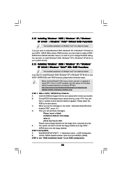
...174; VistaTM With RAID Functions The installation procedures for Windows VistaTM are subject to change the BIOS setting. If there is supposed to include SP4. A. Please select CD- E. A. Insert the ASRock Support CD into the floppy drive, and press any key to start Please insert a floppy...below website for proper procedures of system boot-up, press key, and then a window for boot devices selection appears. STEP 2: Set Up BIOS. Set the "SATAII Operation Mode" option from [non-RAID] to set RAID configuration. 22 When you want to install Windows® 2000,...
...174; VistaTM With RAID Functions The installation procedures for Windows VistaTM are subject to change the BIOS setting. If there is supposed to include SP4. A. Please select CD- E. A. Insert the ASRock Support CD into the floppy drive, and press any key to start Please insert a floppy...below website for proper procedures of system boot-up, press key, and then a window for boot devices selection appears. STEP 2: Set Up BIOS. Set the "SATAII Operation Mode" option from [non-RAID] to set RAID configuration. 22 When you want to install Windows® 2000,...
User Manual
Page 23
... Technology This motherboard supports Untied Overclocking Technology, which is untied during overclocking, FSB enjoys better margin due to [CPU, PCIE, Async.]. At the beginning of BIOS setup to set the selection from [Auto] to fixed PCI / PCIE buses. Select the driver to install according to install a third-party SCSI or RAID...
... Technology This motherboard supports Untied Overclocking Technology, which is untied during overclocking, FSB enjoys better margin due to [CPU, PCIE, Async.]. At the beginning of BIOS setup to set the selection from [Auto] to fixed PCI / PCIE buses. Select the driver to install according to install a third-party SCSI or RAID...
User Manual
Page 24
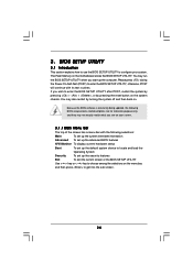
...by pressing the reset button on your system. The Flash Memory on . Please press during the Power-On-Self-Test (POST) to enter the BIOS SETUP UTILITY, otherwise, POST will continue with the following selections: Main To set up the system time/date information Advanced To set up the advanced... BIOS features H/W Monitor To display current hardware status Boot To set up the default system device to get into the sub screen. 24 You may...
...by pressing the reset button on your system. The Flash Memory on . Please press during the Power-On-Self-Test (POST) to enter the BIOS SETUP UTILITY, otherwise, POST will continue with the following selections: Main To set up the system time/date information Advanced To set up the advanced... BIOS features H/W Monitor To display current hardware status Boot To set up the default system device to get into the sub screen. 24 You may...
User Manual
Page 25
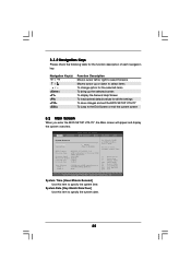
... Main Advanced H/W Monitor Boot Security Exit System Overview System Time System Date [17:00:09] [Thu 03/16/2006] BIOS Version : K8NF4G-VSTA BIOS P1.0 Processor Type : AMD Athlon(tm) 64 Processor 3400+ (64bit supported) Processor Speed : 2200 MHz Microcode Update : F7A/3A L1 Cache Size : 128KB L2 Cache ... this item to specify the system date. 25 3.1.2 Navigation Keys Please check the following table for all the settings To save changes and exit the BIOS SETUP UTILITY To jump to specify the system time. System Date [Day Month/Date/Year] Use this item to the Exit Screen or exit the...
... Main Advanced H/W Monitor Boot Security Exit System Overview System Time System Date [17:00:09] [Thu 03/16/2006] BIOS Version : K8NF4G-VSTA BIOS P1.0 Processor Type : AMD Athlon(tm) 64 Processor 3400+ (64bit supported) Processor Speed : 2200 MHz Microcode Update : F7A/3A L1 Cache Size : 128KB L2 Cache ... this item to specify the system date. 25 3.1.2 Navigation Keys Please check the following table for all the settings To save changes and exit the BIOS SETUP UTILITY To jump to specify the system time. System Date [Day Month/Date/Year] Use this item to the Exit Screen or exit the...


