RAID Installation Guide
Page 2
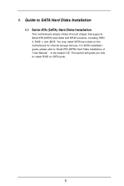
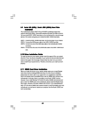
You may install SATA hard disks on SATA ports. 2 Guide to Serial ATA (SATA) Hard Disks Installation of "U ser Manual " in the support CD. This section will guide you how to create RAID on this motherboard for internal storage devices. For SATA installation guide, please refer to SATA Hard Disks Installation 1.1 Serial ATA (SATA) Hard Disks Installation This motherboard adopts nVidia nForce3 chipset that supports Serial ATA (SATA) hard disks with RAID functions, including RAID 0, RAID 1, and JBOD. 1.
You may install SATA hard disks on SATA ports. 2 Guide to Serial ATA (SATA) Hard Disks Installation of "U ser Manual " in the support CD. This section will guide you how to create RAID on this motherboard for internal storage devices. For SATA installation guide, please refer to SATA Hard Disks Installation 1.1 Serial ATA (SATA) Hard Disks Installation This motherboard adopts nVidia nForce3 chipset that supports Serial ATA (SATA) hard disks with RAID functions, including RAID 0, RAID 1, and JBOD. 1.
RAID Installation Guide
Page 4
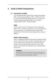
... 2.1 Introduction of RAID, and the guide to read and write data in parallel, interleaved stacks. This section will introduce the basic knowledge of RAID This motherboard adopts nVidia nForce3 chipset that optimizes two identical hard disk drives to configure RAID 0, RAID 1, and JBOD settings.
... 2.1 Introduction of RAID, and the guide to read and write data in parallel, interleaved stacks. This section will introduce the basic knowledge of RAID This motherboard adopts nVidia nForce3 chipset that optimizes two identical hard disk drives to configure RAID 0, RAID 1, and JBOD settings.

User Manual
Page 3
... 30 3.3.4 IDE Configuration 31 3.3.5 PCIPnP Configuration 33 3.3.6 Floppy Configuration 34 3 Contents 1 . Introduction 5 1.1 Package Contents 5 1.2 Specifications 6 1.3 Minimum Hardware Requirement Table for Windows® VistaTM Basic Logo 9 1.4 Motherboard Layout 10 1.5 HD 8CH I/O 11 2 .
... 30 3.3.4 IDE Configuration 31 3.3.5 PCIPnP Configuration 33 3.3.6 Floppy Configuration 34 3 Contents 1 . Introduction 5 1.1 Package Contents 5 1.2 Specifications 6 1.3 Minimum Hardware Requirement Table for Windows® VistaTM Basic Logo 9 1.4 Motherboard Layout 10 1.5 HD 8CH I/O 11 2 .

User Manual
Page 5
... setup and information of this manual will be available on ASRock website as well. In case any modifications of the Support CD. ASRock website http://www.asrock.com 1.1 Package Contents 1 x ASRock K8NF4G-VSTA Motherboard (Micro ATX Form Factor: 9.6-in x 8.0-in, 24.4 cm x 20.3 cm) 1 x ASRock K8NF4G-VSTA Quick Installation Guide 1 x ASRock K8NF4G-VSTA Support CD 1 x Ultra ATA 66/100/133 IDE Ribbon Cable...
... setup and information of this manual will be available on ASRock website as well. In case any modifications of the Support CD. ASRock website http://www.asrock.com 1.1 Package Contents 1 x ASRock K8NF4G-VSTA Motherboard (Micro ATX Form Factor: 9.6-in x 8.0-in, 24.4 cm x 20.3 cm) 1 x ASRock K8NF4G-VSTA Quick Installation Guide 1 x ASRock K8NF4G-VSTA Support CD 1 x Ultra ATA 66/100/133 IDE Ribbon Cable...
User Manual
Page 7
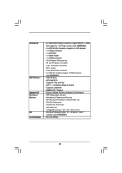
..." function) (see CAUTION 6) - 2 x ATA133 IDE connectors (support 4 x IDE devices) - 1 x Floppy connector - 1 x IR header - 1 x Game header - 1 x COM port header - AMI Legal BIOS - Supports "Plug and Play" - Motherboard Temperature Sensing -
..." function) (see CAUTION 6) - 2 x ATA133 IDE connectors (support 4 x IDE devices) - 1 x Floppy connector - 1 x IR header - 1 x Game header - 1 x COM port header - AMI Legal BIOS - Supports "Plug and Play" - Motherboard Temperature Sensing -
User Manual
Page 8
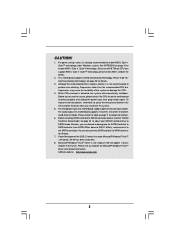
... CPU. 4. To improve heat dissipation, remember to SATAII mode. ASRock website http://www.asrock.com 8 This motherboard supports Untied Overclocking Technology. Please read the "SATAII Hard Disk Setup Guide" on the motherboard functions properly and unplug the power cord, then plug it is detected...174; Windows® VistaTM driver is not recommended to the SATAII connector. See APPENDIX on page 11 for details. 2. Although this motherboard offers stepless control, it to perform over-clocking. Besides, you install the PC system. 5. CAUTION! 1. Before you resume the ...
... CPU. 4. To improve heat dissipation, remember to SATAII mode. ASRock website http://www.asrock.com 8 This motherboard supports Untied Overclocking Technology. Please read the "SATAII Hard Disk Setup Guide" on the motherboard functions properly and unplug the power cord, then plug it is detected...174; Windows® VistaTM driver is not recommended to the SATAII connector. See APPENDIX on page 11 for details. 2. Although this motherboard offers stepless control, it to perform over-clocking. Besides, you install the PC system. 5. CAUTION! 1. Before you resume the ...
User Manual
Page 9
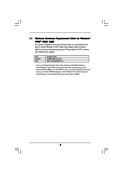
... submit Windows® VistaTM Basic logo, please follow the below table for Windows® VistaTM Basic Logo For system integrators and users who purchase our motherboard and plan to 64MB or less than 64MB. Please adopt the CPU, memory, and VGA that we suggest.
... submit Windows® VistaTM Basic logo, please follow the below table for Windows® VistaTM Basic Logo For system integrators and users who purchase our motherboard and plan to 64MB or less than 64MB. Please adopt the CPU, memory, and VGA that we suggest.

User Manual
Page 12
.... Hold components by the edges and do so may damage the motherboard. 12 Before you install or remove any motherboard settings. Failure to the motherboard, peripherals, and/or components. 1. Doing so may cause severe damage to do not touch the ICs. 4. 2. Installation K8NF4G-VSTA is a Micro ATX form factor (9.6-in x 8.0-in the bag that the...
.... Hold components by the edges and do so may damage the motherboard. 12 Before you install or remove any motherboard settings. Failure to the motherboard, peripherals, and/or components. 1. Doing so may cause severe damage to do not touch the ICs. 4. 2. Installation K8NF4G-VSTA is a Micro ATX form factor (9.6-in x 8.0-in the bag that the...

User Manual
Page 13
Step 3. Carefully insert the CPU into the socket until it is locked. DO NOT force the CPU into this motherboard, it firmly on the side tab to avoid bending of the CPU fan and the heatsink. 13 The lever clicks on the socket while you ...
Step 3. Carefully insert the CPU into the socket until it is locked. DO NOT force the CPU into this motherboard, it firmly on the side tab to avoid bending of the CPU fan and the heatsink. 13 The lever clicks on the socket while you ...

User Manual
Page 14
Align a DIMM on the slot such that the notch on the DIMM matches the break on the slot. Step 2. Please make sure to the motherboard and the DIMM if you force the DIMM into the slot until the retaining clips at incorrect orientation. Step 3. Firmly insert the DIMM into the ...slot at both ends fully snap back in one correct orientation. 2.3 Installation of Memory Modules (DIMM) This motherboard is properly seated. 14 notch break notch break The DIMM only fits in place and the DIMM is equipped with two 184-pin DDR (Double...
Align a DIMM on the slot such that the notch on the DIMM matches the break on the slot. Step 2. Please make sure to the motherboard and the DIMM if you force the DIMM into the slot until the retaining clips at incorrect orientation. Step 3. Firmly insert the DIMM into the ...slot at both ends fully snap back in one correct orientation. 2.3 Installation of Memory Modules (DIMM) This motherboard is properly seated. 14 notch break notch break The DIMM only fits in place and the DIMM is equipped with two 184-pin DDR (Double...
User Manual
Page 15
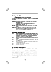
...card connector with PCIE2 slot; Fasten the card to insert an ASRock HDMR card with x16 lane width graphics cards. PCI Slots: PCI slots are 2 PCI Express slots, 2 PCI slots and 1 HDMR slot on K8NF4G-VSTA motherboard. Remove the bracket facing the slot that you intend to install ...expansion cards that have the 32-bit PCI interface. Step 4. Step 6. Installing an expansion card Step 1. Step 2. Remove the system unit cover (if your motherboard is [Auto], which will disable...
...card connector with PCIE2 slot; Fasten the card to insert an ASRock HDMR card with x16 lane width graphics cards. PCI Slots: PCI slots are 2 PCI Express slots, 2 PCI slots and 1 HDMR slot on K8NF4G-VSTA motherboard. Remove the bracket facing the slot that you intend to install ...expansion cards that have the 32-bit PCI interface. Step 4. Step 6. Installing an expansion card Step 1. Step 2. Remove the system unit cover (if your motherboard is [Auto], which will disable...
User Manual
Page 16
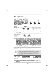
... 2 Amp and higher standby current provided by power supply. Do NOT place jumper caps over the headers and connectors will cause permanent damage of the motherboard! • Floppy Connector (33-pin FLOPPY1) (see p.9 No. 20) Pin1 FLOPPY1 the red-striped side to short pin2 and pin3 on pins, the jumper is...
... 2 Amp and higher standby current provided by power supply. Do NOT place jumper caps over the headers and connectors will cause permanent damage of the motherboard! • Floppy Connector (33-pin FLOPPY1) (see p.9 No. 20) Pin1 FLOPPY1 the red-striped side to short pin2 and pin3 on pins, the jumper is...

User Manual
Page 17
... (SATA II_1: see p.9, No. 13) (SATA II_2: see p.9 No. 17) USB_PWR P-7 P+7 GND DUMMY 1 GND P+6 P-6 USB_PWR HD 8CH I /O panel are not sufficient, this motherboard, please set the IDE device as "Master". Primary IDE Connector (Blue) (39-pin IDE1, see p.9 No. 7) Secondary IDE Connector (Black) (39-pin IDE2, see p.9 No.... 6) PIN1 IDE1 PIN1 IDE2 connect the blue end to the motherboard connect the black end to the IDE devices 80-conductor ATA 66/100/133 cable Note: If you use only one IDE device on this...
... (SATA II_1: see p.9, No. 13) (SATA II_2: see p.9 No. 17) USB_PWR P-7 P+7 GND DUMMY 1 GND P+6 P-6 USB_PWR HD 8CH I /O panel are not sufficient, this motherboard, please set the IDE device as "Master". Primary IDE Connector (Blue) (39-pin IDE1, see p.9 No. 7) Secondary IDE Connector (Black) (39-pin IDE2, see p.9 No.... 6) PIN1 IDE1 PIN1 IDE2 connect the blue end to the motherboard connect the black end to the IDE devices 80-conductor ATA 66/100/133 cable Note: If you use only one IDE device on this...
User Manual
Page 21
... Audio driver before installing HDMR card driver; in our support CD. 2.9 Serial ATA (SATA) / Serial ATAII (SATAII) Hard Disks Installation This motherboard adopts nVidia® nForce 410 MCP southbridge chipset that supports Serial ATA (SATA) / Serial ATAII (SATAII) hard disks and RAID functions. This ...When you install the drivers to your system, please make sure to restart your optical drive first. Then, the drivers compatible to this motherboard, you install can work . STEP 3: Connect one end of your system can work successfully. 21 It is no problem on the...
... Audio driver before installing HDMR card driver; in our support CD. 2.9 Serial ATA (SATA) / Serial ATAII (SATAII) Hard Disks Installation This motherboard adopts nVidia® nForce 410 MCP southbridge chipset that supports Serial ATA (SATA) / Serial ATAII (SATAII) hard disks and RAID functions. This ...When you install the drivers to your system, please make sure to restart your optical drive first. Then, the drivers compatible to this motherboard, you install can work . STEP 3: Connect one end of your system can work successfully. 21 It is no problem on the...
User Manual
Page 23
... need to check the installation guide in the folder at the following path: .. \Information\Manual\RAID Utility for Windows Guide 2.14 Untied Overclocking Technology This motherboard supports Untied Overclocking Technology, which is located in the Support CD for Windows Guide" in the fixed mode so that FSB can start to configure...
... need to check the installation guide in the folder at the following path: .. \Information\Manual\RAID Utility for Windows Guide 2.14 Untied Overclocking Technology This motherboard supports Untied Overclocking Technology, which is located in the Support CD for Windows Guide" in the fixed mode so that FSB can start to configure...
User Manual
Page 24
... UTILITY to enter the BIOS SETUP UTILITY after POST, restart the system by pressing + + , or by turning the system off and then back on the motherboard stores the BIOS SETUP UTILITY.
... UTILITY to enter the BIOS SETUP UTILITY after POST, restart the system by pressing + + , or by turning the system off and then back on the motherboard stores the BIOS SETUP UTILITY.

User Manual
Page 36
... status of the hardware on your system, including the parameters of USB controller. Or you to enable or disable the use of the CPU temperature, motherboard temperature, CPU fan speed, chassis fan speed, and the critical voltage.
... status of the hardware on your system, including the parameters of USB controller. Or you to enable or disable the use of the CPU temperature, motherboard temperature, CPU fan speed, chassis fan speed, and the critical voltage.
User Manual
Page 40
... BIN folder in the Support CD to visit ASRock's website at http://www.asrock.com; or you need to contact ASRock or want to know more information. 4.2 Support CD Information The Support CD that came with the motherboard contains necessary drivers and useful utilities that the motherboard supports. Refer to activate the devices. 4.2.3 Utilities Menu...
... BIN folder in the Support CD to visit ASRock's website at http://www.asrock.com; or you need to contact ASRock or want to know more information. 4.2 Support CD Information The Support CD that came with the motherboard contains necessary drivers and useful utilities that the motherboard supports. Refer to activate the devices. 4.2.3 Utilities Menu...

Quick Installation Guide
Page 1
... Published March 2006 Copyright©2006 ASRock INC. All rights reserved. 1 ASRock K8NF4G-VSTA Motherboard English ASRock assumes no event shall ASRock, its directors, officers, employees, or agents be constructed as a commitment by ASRock. This device complies with Part 15 of ASRock Inc. Operation is subject to the ... damages for loss of profits, loss of business, loss of data, interruption of business and the like), even if ASRock has been advised of the possibility of merchantability or fitness for backup purpose, without intent to infringe. Disclaimer: Specifications and...
... Published March 2006 Copyright©2006 ASRock INC. All rights reserved. 1 ASRock K8NF4G-VSTA Motherboard English ASRock assumes no event shall ASRock, its directors, officers, employees, or agents be constructed as a commitment by ASRock. This device complies with Part 15 of ASRock Inc. Operation is subject to the ... damages for loss of profits, loss of business, loss of data, interruption of business and the like), even if ASRock has been advised of the possibility of merchantability or fitness for backup purpose, without intent to infringe. Disclaimer: Specifications and...

Quick Installation Guide
Page 2
Motherboard Layout English 1 PS2_USB_PW1 Jumper 16 Chassis Speaker Header (SPEAKER 1) 2 ATX 12V Power Connector (ATX12V1) 17 USB 2.0 Header (USB67, Blue) 3 754-Pin CPU Socket 18 Infrared ...) 28 ATX Power Connector (ATXPWR1) 14 Chassis Fan Connector (CHA_FAN1) 29 Serial Port Connector (COM1) 15 System Panel Header (PANEL1) 30 CPU Fan Connector (CPU_FAN1) 2 ASRock K8NF4G-VSTA Motherboard
Motherboard Layout English 1 PS2_USB_PW1 Jumper 16 Chassis Speaker Header (SPEAKER 1) 2 ATX 12V Power Connector (ATX12V1) 17 USB 2.0 Header (USB67, Blue) 3 754-Pin CPU Socket 18 Infrared ...) 28 ATX Power Connector (ATXPWR1) 14 Chassis Fan Connector (CHA_FAN1) 29 Serial Port Connector (COM1) 15 System Panel Header (PANEL1) 30 CPU Fan Connector (CPU_FAN1) 2 ASRock K8NF4G-VSTA Motherboard

