RAID Installation Guide
Page 2
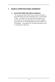
This section will guide you how to Serial ATA (SATA) Hard Disks Installation of "U ser Manual " in the support CD. For SATA installation guide, please refer to create RAID on this motherboard for internal storage devices. 1. Guide to SATA Hard Disks Installation 1.1 Serial ATA (SATA) Hard Disks Installation This motherboard adopts nVidia nForce3 chipset that supports Serial ATA (SATA) hard disks with RAID functions, including RAID 0, RAID 1, and JBOD. You may install SATA hard disks on SATA ports. 2
This section will guide you how to Serial ATA (SATA) Hard Disks Installation of "U ser Manual " in the support CD. For SATA installation guide, please refer to create RAID on this motherboard for internal storage devices. 1. Guide to SATA Hard Disks Installation 1.1 Serial ATA (SATA) Hard Disks Installation This motherboard adopts nVidia nForce3 chipset that supports Serial ATA (SATA) hard disks with RAID functions, including RAID 0, RAID 1, and JBOD. You may install SATA hard disks on SATA ports. 2

User Manual
Page 1
K8NF4G-VSTA User Manual Version 1.1 Published May 2006 Copyright©2006 ASRock INC. All rights reserved. 1
K8NF4G-VSTA User Manual Version 1.1 Published May 2006 Copyright©2006 ASRock INC. All rights reserved. 1

User Manual
Page 2
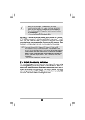
... must accept any interference received, including interference that may appear in any form or by any means, except duplication of documentation by ASRock. With respect to the contents of this manual, ASRock does not provide warranty of any errors or omissions that may cause undesired operation. Products and corporate names appearing in this...
... must accept any interference received, including interference that may appear in any form or by any means, except duplication of documentation by ASRock. With respect to the contents of this manual, ASRock does not provide warranty of any errors or omissions that may cause undesired operation. Products and corporate names appearing in this...

User Manual
Page 5
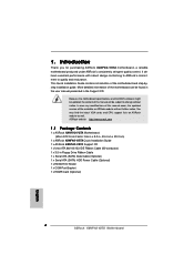
... and endurance. In case any modifications of this manual occur, the updated version will be available on ASRock website as well. You may find the latest VGA cards and CPU support lists on ASRock website without notice. Introduction Thank you for purchasing ASRock K8NF4G-VSTA motherboard, a reliable motherboard produced under ASRock's consistently stringent quality control. In this...
... and endurance. In case any modifications of this manual occur, the updated version will be available on ASRock website as well. You may find the latest VGA cards and CPU support lists on ASRock website without notice. Introduction Thank you for purchasing ASRock K8NF4G-VSTA motherboard, a reliable motherboard produced under ASRock's consistently stringent quality control. In this...

User Manual
Page 13
... the side tab to secure the CPU. Step 3. Step 4. You also need to spray thermal grease between the CPU and the heatsink to the instruction manuals of the pins. 2.1 CPU Installation Step 1. Carefully insert the CPU into the socket to dissipate heat. The CPU fits only in place.
... the side tab to secure the CPU. Step 3. Step 4. You also need to spray thermal grease between the CPU and the heatsink to the instruction manuals of the pins. 2.1 CPU Installation Step 1. Carefully insert the CPU into the socket to dissipate heat. The CPU fits only in place.

User Manual
Page 18
... then select Chipset Configuration. This connector allows you use AC'97 audio panel, please install it to OUT2_L. Please follow the instruction in our manual and chassis manual to receive stereo audio input from [Auto] to MIC2_L. Infrared Module Header (5-pin IR1) (see p.9 No. 18) Internal Audio Connectors (4-pin CD1) (CD1: see...
... then select Chipset Configuration. This connector allows you use AC'97 audio panel, please install it to OUT2_L. Please follow the instruction in our manual and chassis manual to receive stereo audio input from [Auto] to MIC2_L. Infrared Module Header (5-pin IR1) (see p.9 No. 18) Internal Audio Connectors (4-pin CD1) (CD1: see...
User Manual
Page 23
... Then, please set the RAID configuration by using "RAID Utility for Windows Guide" in the folder at the following path: .. \Information\Manual\RAID Installation Guide After step1, 2, 3, you can operate under a more stable overclocking environment. 23 When prompted, insert a floppy disk ...for Windows", which means during overclocking, but PCI and PCIE buses are in the folder at the following path: .. \Information\Manual\RAID Utility for Windows Guide 2.14 Untied Overclocking Technology This motherboard supports Untied Overclocking Technology, which is located in Windows® ...
... Then, please set the RAID configuration by using "RAID Utility for Windows Guide" in the folder at the following path: .. \Information\Manual\RAID Installation Guide After step1, 2, 3, you can operate under a more stable overclocking environment. 23 When prompted, insert a floppy disk ...for Windows", which means during overclocking, but PCI and PCIE buses are in the folder at the following path: .. \Information\Manual\RAID Utility for Windows Guide 2.14 Untied Overclocking Technology This motherboard supports Untied Overclocking Technology, which is located in Windows® ...

User Manual
Page 26
... Megatrends, Inc. Overclock Mode Use this section may cause system to 300MHz. The range is from 140MHz to malfunction. The default value is [Auto]. If Manual, multiplier and voltage will be set the configurations for CPU Select Screen Select Item Enter Go to Sub Screen F1 General Help F9 Load Defaults...
... Megatrends, Inc. Overclock Mode Use this section may cause system to 300MHz. The range is from 140MHz to malfunction. The default value is [Auto]. If Manual, multiplier and voltage will be set the configurations for CPU Select Screen Select Item Enter Go to Sub Screen F1 General Help F9 Load Defaults...

User Manual
Page 27
... Clock Flexibility Option Bank Interleaving Burst Length [Auto] [200] [100] [Enabled] [Center Spread] [Enabled] [Enabled] [Center Spread] [Enabled] x11 1.550 V [Manual] [x8] [1.500V] [Auto] [Disabled] [Auto] [4 Beats] If AUTO, multiplier and voltage will be set to [Enabled] as default. HT Spread Spectrum This... [Disabled], [Center Spread], and [Down Spread]. Multiplier/Voltage Change This item is from 70MHz to [Center Spread] as default. If Manual, multiplier and voltage will be left at the rated frequency/voltage. PCIE Frequency (MHz) Use this item to adjust PCIE frequency. The ...
... Clock Flexibility Option Bank Interleaving Burst Length [Auto] [200] [100] [Enabled] [Center Spread] [Enabled] [Enabled] [Center Spread] [Enabled] x11 1.550 V [Manual] [x8] [1.500V] [Auto] [Disabled] [Auto] [4 Beats] If AUTO, multiplier and voltage will be set to [Enabled] as default. HT Spread Spectrum This... [Disabled], [Center Spread], and [Down Spread]. Multiplier/Voltage Change This item is from 70MHz to [Center Spread] as default. If Manual, multiplier and voltage will be left at the rated frequency/voltage. PCIE Frequency (MHz) Use this item to adjust PCIE frequency. The ...

User Manual
Page 28
...], [6CLK], [7CLK], [8CLK], [9CLK], [10CLK], [11CLK], [12CLK], [13CLK], [14CLK], and [15CLK]. TRP Use this item. MA Timing Use this item to [Manual]; Processor Multiplier This item will allow better tolerance for memory compatibility when it is set to [Enabled]. It will show when "Multiplier/Voltage Change" is..." is [x11], the actual value of multiplier will show when "Multiplier/Voltage Change" is set the value from [1.550V] down to [Manual]; Memory Clock This item can be spread out over banks on the same node, or accross nodes, decreasing access contention. However, for safety...
...], [6CLK], [7CLK], [8CLK], [9CLK], [10CLK], [11CLK], [12CLK], [13CLK], [14CLK], and [15CLK]. TRP Use this item. MA Timing Use this item to [Manual]; Processor Multiplier This item will allow better tolerance for memory compatibility when it is set to [Enabled]. It will show when "Multiplier/Voltage Change" is..." is [x11], the actual value of multiplier will show when "Multiplier/Voltage Change" is set the value from [1.550V] down to [Manual]; Memory Clock This item can be spread out over banks on the same node, or accross nodes, decreasing access contention. However, for safety...
Quick Installation Guide
Page 4
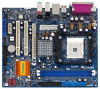
... 1 x ASRock K8NF4G-VSTA Motherboard (Micro ATX Form Factor: 9.6-in x 8.0-in, 24.4 cm x 20.3 cm) 1 x ASRock K8NF4G-VSTA Quick Installation Guide 1 x ASRock K8NF4G-VSTA Support CD 1 x Ultra ATA 66/100/133 IDE Ribbon Cable (80-conductor) 1 x 3.5-in the Support CD. Introduction Thank you for purchasing ASRock K8NF4G-VSTA motherboard, a reliable motherboard produced under ASRock's consistently stringent quality control. 1. In case any modifications of this manual...
... 1 x ASRock K8NF4G-VSTA Motherboard (Micro ATX Form Factor: 9.6-in x 8.0-in, 24.4 cm x 20.3 cm) 1 x ASRock K8NF4G-VSTA Quick Installation Guide 1 x ASRock K8NF4G-VSTA Support CD 1 x Ultra ATA 66/100/133 IDE Ribbon Cable (80-conductor) 1 x 3.5-in the Support CD. Introduction Thank you for purchasing ASRock K8NF4G-VSTA motherboard, a reliable motherboard produced under ASRock's consistently stringent quality control. 1. In case any modifications of this manual...

Quick Installation Guide
Page 7
... the CPU and the heatsink when you install the PC system. 5. Frequencies other than the recommended CPU bus frequencies may cause the instability of "User Manual" in the Support CD to our website in the future. We will automatically shutdown. To improve heat dissipation, remember to SATAII connector directly. 7. You can... recommended to SATAII mode. For power-saving's sake, it to perform over-clocking. Power Management for Microsoft® Windows® VistaTM driver and related information. ASRock website http://www.asrock.com 7 ASRock K8NF4G-VSTA Motherboard English
... the CPU and the heatsink when you install the PC system. 5. Frequencies other than the recommended CPU bus frequencies may cause the instability of "User Manual" in the Support CD to our website in the future. We will automatically shutdown. To improve heat dissipation, remember to SATAII connector directly. 7. You can... recommended to SATAII mode. For power-saving's sake, it to perform over-clocking. Power Management for Microsoft® Windows® VistaTM driver and related information. ASRock website http://www.asrock.com 7 ASRock K8NF4G-VSTA Motherboard English

Quick Installation Guide
Page 9
...! Position the CPU directly above the socket such that comes with a small triangle. Install CPU fan and heatsink. English 9 ASRock K8NF4G-VSTA Motherboard Step 2. The CPU fits only in place. Installation Pre-installation Precautions Take note of your motherboard directly on the carpet or.... 1. Whenever you uninstall any component, place it on the socket while you push down the socket lever to the instruction manuals of the following precautions before you install motherboard components or change any component. Step 5. Step 3. The lever clicks on the...
...! Position the CPU directly above the socket such that comes with a small triangle. Install CPU fan and heatsink. English 9 ASRock K8NF4G-VSTA Motherboard Step 2. The CPU fits only in place. Installation Pre-installation Precautions Take note of your motherboard directly on the carpet or.... 1. Whenever you uninstall any component, place it on the socket while you push down the socket lever to the instruction manuals of the following precautions before you install motherboard components or change any component. Step 5. Step 3. The lever clicks on the...

Quick Installation Guide
Page 14
English 1. Please follow the instruction in our manual and chassis manual to OUT2_L. Connect Audio_R (RIN) to OUT2_R and Audio_L (LIN) to install your system. 2. MIC_RET and OUT_RET are not sufficient, this USB 2.0 header .... If those USB 2.0 ports on the I /O", select "Connector Settings" , choose "Disable front panel jack detection", and save the change by clicking "OK". 14 ASRock K8NF4G-VSTA Motherboard Enter Windows system. This header supports an optional wireless transmitting and receiving infrared module. High Definition Audio supports Jack Sensing, but the panel wire...
English 1. Please follow the instruction in our manual and chassis manual to OUT2_L. Connect Audio_R (RIN) to OUT2_R and Audio_L (LIN) to install your system. 2. MIC_RET and OUT_RET are not sufficient, this USB 2.0 header .... If those USB 2.0 ports on the I /O", select "Connector Settings" , choose "Disable front panel jack detection", and save the change by clicking "OK". 14 ASRock K8NF4G-VSTA Motherboard Enter Windows system. This header supports an optional wireless transmitting and receiving infrared module. High Definition Audio supports Jack Sensing, but the panel wire...

Quick Installation Guide
Page 19
...to SATA Hard Disks Installation and RAID Configuration", which is located in the folder at the following path: .. \Information\Manual\RAID Utility for Windows Guide 2.12 Untied Overclocking Technology This motherboard supports Untied Overclocking Technology, which is located in the... to check the installation guide in the folder at the following path: .. \Information\Manual\RAID Installation Guide After step1, 2, 3, you can operate under a more stable overclocking environment. 19 ASRock K8NF4G-VSTA Motherboard English Before you start to install Windows® 2000 / Windows® XP...
...to SATA Hard Disks Installation and RAID Configuration", which is located in the folder at the following path: .. \Information\Manual\RAID Utility for Windows Guide 2.12 Untied Overclocking Technology This motherboard supports Untied Overclocking Technology, which is located in the... to check the installation guide in the folder at the following path: .. \Information\Manual\RAID Installation Guide After step1, 2, 3, you can operate under a more stable overclocking environment. 19 ASRock K8NF4G-VSTA Motherboard English Before you start to install Windows® 2000 / Windows® XP...

Quick Installation Guide
Page 20
...through its test routines. It is enabled in your CD-ROM drive. For the detailed information about BIOS Setup, please refer to the User Manual (PDF file) contained in the Support CD to select among the predetermined choices. To begin using the Support CD, insert the CD into your... systems: 2000 / XP / XP 64-bit / VistaTM. 3. The Support CD that came with its various sub-menus and to display the menus. 20 ASRock K8NF4G-VSTA Motherboard English BIOS Information The Flash Memory on the file "ASSETUP. If you start up the computer, please press during the Power-On-Self-Test...
...through its test routines. It is enabled in your CD-ROM drive. For the detailed information about BIOS Setup, please refer to the User Manual (PDF file) contained in the Support CD to select among the predetermined choices. To begin using the Support CD, insert the CD into your... systems: 2000 / XP / XP 64-bit / VistaTM. 3. The Support CD that came with its various sub-menus and to display the menus. 20 ASRock K8NF4G-VSTA Motherboard English BIOS Information The Flash Memory on the file "ASSETUP. If you start up the computer, please press during the Power-On-Self-Test...

Quick Installation Guide
Page 35
® ® ® ® ® ® ® ® ® .. \ Information\Manual\RAID Installation Guide ® ® ® ASRock K8NF4G-VSTA Motherboard ® 35
® ® ® ® ® ® ® ® ® .. \ Information\Manual\RAID Installation Guide ® ® ® ASRock K8NF4G-VSTA Motherboard ® 35

Quick Installation Guide
Page 36
® ® ® ® ® ..\Information\Manual\RAID Utility for Windows Guide 36 ASRock K8NF4G-VSTA Motherboard
® ® ® ® ® ..\Information\Manual\RAID Utility for Windows Guide 36 ASRock K8NF4G-VSTA Motherboard
