User Manual
Page 2
... no responsibility for a particular purpose. Operation is subject to infringe. CALIFORNIA, USA ONLY The Lithium battery adopted on this motherboard contains Perchlorate, a toxic substance controlled in Perchlorate Best Management Practices (BMP) regulations passed by the purchaser for loss of ... from any errors or omissions that may cause undesired operation. "Perchlorate Material-special handling may not be constructed as a commitment by ASRock. Copyright Notice: No part of this manual may be reproduced, transcribed, transmitted, or translated in any language, in any form or...
... no responsibility for a particular purpose. Operation is subject to infringe. CALIFORNIA, USA ONLY The Lithium battery adopted on this motherboard contains Perchlorate, a toxic substance controlled in Perchlorate Best Management Practices (BMP) regulations passed by the purchaser for loss of ... from any errors or omissions that may cause undesired operation. "Perchlorate Material-special handling may not be constructed as a commitment by ASRock. Copyright Notice: No part of this manual may be reproduced, transcribed, transmitted, or translated in any language, in any form or...

User Manual
Page 3
... and Connectors 17 2.7 Serial ATA (SATA) Hard Disks Installation 21 2.8 Hot Plug and Hot Swap Functions for Windows® VistaTM Premium 2007 and Basic Logo 9 1.4 Motherboard Layout 10 1.5 ASRock 8CH I/O 11 2 .
... and Connectors 17 2.7 Serial ATA (SATA) Hard Disks Installation 21 2.8 Hot Plug and Hot Swap Functions for Windows® VistaTM Premium 2007 and Basic Logo 9 1.4 Motherboard Layout 10 1.5 ASRock 8CH I/O 11 2 .
User Manual
Page 5
... well. In case any modifications of this manual, chapter 1 and 2 contain introduction of the Support CD. ASRock website http://www.asrock.com 1.1 Package Contents 1 x ASRock K8NF3-VSTA Motherboard (ATX Form Factor: 12.0-in x 7.5-in, 30.5 cm x 19.1 cm) 1 x ASRock K8NF3-VSTA Quick Installation Guide 1 x ASRock K8NF3-VSTA Support CD 1 x Ultra ATA 66/100/133 IDE Ribbon Cable (80-conductor) 1 x 3.5-in Floppy Drive...
... well. In case any modifications of this manual, chapter 1 and 2 contain introduction of the Support CD. ASRock website http://www.asrock.com 1.1 Package Contents 1 x ASRock K8NF3-VSTA Motherboard (ATX Form Factor: 12.0-in x 7.5-in, 30.5 cm x 19.1 cm) 1 x ASRock K8NF3-VSTA Quick Installation Guide 1 x ASRock K8NF3-VSTA Support CD 1 x Ultra ATA 66/100/133 IDE Ribbon Cable (80-conductor) 1 x 3.5-in Floppy Drive...
User Manual
Page 8
...® VistaTM / VistaTM 64-bit driver keeps on the AGP slot of the system or damage the CPU. 3. ASRock website http://www.asrock.com 8 Before you install the PC system. 4. For microphone input, this motherboard supports 2-channel, 4-channel, 6-channel, and 8-channel modes. Power Management for proper connection. 6. As long as we have the...
...® VistaTM / VistaTM 64-bit driver keeps on the AGP slot of the system or damage the CPU. 3. ASRock website http://www.asrock.com 8 Before you install the PC system. 4. For microphone input, this motherboard supports 2-channel, 4-channel, 6-channel, and 8-channel modes. Power Management for proper connection. 6. As long as we have the...
User Manual
Page 9
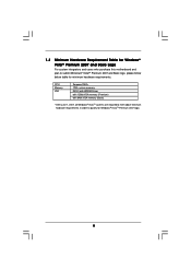
1.3 Minimum Hardware Requirement Table for Windows® VistaTM Premium 2007 and Basic Logo For system integrators and users who purchase this motherboard and plan to qualify for minimum hardware requirements. CPU Memory VGA Sempron 2500+ 1GB system memory DX9.0 with WDDM Driver with 128bit VGA memory (Premium) ...
1.3 Minimum Hardware Requirement Table for Windows® VistaTM Premium 2007 and Basic Logo For system integrators and users who purchase this motherboard and plan to qualify for minimum hardware requirements. CPU Memory VGA Sempron 2500+ 1GB system memory DX9.0 with WDDM Driver with 128bit VGA memory (Premium) ...

User Manual
Page 12
Before you uninstall any component, ensure that the motherboard fits into the screw holes to secure the motherboard to the chassis, please do not over-tighten the screws! Installation K8NF3-VSTA is detached from the wall socket before you handle components. 3. Failure to ensure that the power is switched off or the power cord is...
Before you uninstall any component, ensure that the motherboard fits into the screw holes to secure the motherboard to the chassis, please do not over-tighten the screws! Installation K8NF3-VSTA is detached from the wall socket before you handle components. 3. Failure to ensure that the power is switched off or the power cord is...
User Manual
Page 13
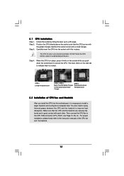
Unlock the socket by lifting the lever up to indicate that it is locked. DO NOT force the CPU into this motherboard, it firmly on the side tab to a 90o angle. Lever 90° Up Socket Corner Small Triangle CPU Golden Triangle STEP 1: Lift Up The Socket ...
Unlock the socket by lifting the lever up to indicate that it is locked. DO NOT force the CPU into this motherboard, it firmly on the side tab to a 90o angle. Lever 90° Up Socket Corner Small Triangle CPU Golden Triangle STEP 1: Lift Up The Socket ...
User Manual
Page 14
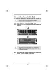
2.3 Installation of Memory Modules (DIMM) This motherboard is properly seated. 14 Unlock a DIMM slot by pressing the retaining clips outward. Align a DIMM on the slot such that the notch on the DIMM .... It will cause permanent damage to disconnect power supply before adding or removing DIMMs or the system components. Step 3. Step 2. Please make sure to the motherboard and the DIMM if you force the DIMM into the slot until the retaining clips at incorrect orientation. Firmly insert the DIMM into the slot...
2.3 Installation of Memory Modules (DIMM) This motherboard is properly seated. 14 Unlock a DIMM slot by pressing the retaining clips outward. Align a DIMM on the slot such that the notch on the DIMM .... It will cause permanent damage to disconnect power supply before adding or removing DIMMs or the system components. Step 3. Step 2. Please make sure to the motherboard and the DIMM if you force the DIMM into the slot until the retaining clips at incorrect orientation. Firmly insert the DIMM into the slot...
User Manual
Page 15
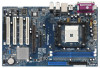
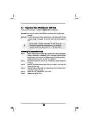
Please read the documentation of your motherboard is used to install expansion cards that have the 32-bit PCI interface. Align the card connector with screws. Step 5. Replace the system cover. 15 ... is unplugged. PCI Slots: PCI slots are 4 PCI slots and 1 AGP slot on K8NF3-VSTA motherboard. Remove the system unit cover (if your AGP card, please check with the AGP card vendors. Step 4. The ASRock AGP slot has a special design of this motherboard! Please do NOT use a 3.3V AGP card on the slot. Step 2. AGP...
Please read the documentation of your motherboard is used to install expansion cards that have the 32-bit PCI interface. Align the card connector with screws. Step 5. Replace the system cover. 15 ... is unplugged. PCI Slots: PCI slots are 4 PCI slots and 1 AGP slot on K8NF3-VSTA motherboard. Remove the system unit cover (if your AGP card, please check with the AGP card vendors. Step 4. The ASRock AGP slot has a special design of this motherboard! Please do NOT use a 3.3V AGP card on the slot. Step 2. AGP...
User Manual
Page 17
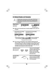
... connector. Serial ATA Connectors (SATA1: see p.10 No. 10) (SATA2: see p.10 No. 8) PIN1 IDE1 PIN1 IDE2 connect the blue end to the motherboard connect the black end to the secondary IDE connector (IDE2, black). Primary IDE Connector (Blue) (39-pin IDE1, see p.10 No. 9) Secondary IDE Connector... the IDE devices 80-conductor ATA 66/100/133 cable Note: If you use only one IDE device on the motherboard. 17 Serial ATA (SATA) Data Cable (Optional) Either end of the motherboard! • Floppy Connector (33-pin FLOPPY1) (see p.10 No. 19) Pin1 FLOPPY1 the red-striped side ...
... connector. Serial ATA Connectors (SATA1: see p.10 No. 10) (SATA2: see p.10 No. 8) PIN1 IDE1 PIN1 IDE2 connect the blue end to the motherboard connect the black end to the secondary IDE connector (IDE2, black). Primary IDE Connector (Blue) (39-pin IDE1, see p.10 No. 9) Secondary IDE Connector... the IDE devices 80-conductor ATA 66/100/133 cable Note: If you use only one IDE device on the motherboard. 17 Serial ATA (SATA) Data Cable (Optional) Either end of the motherboard! • Floppy Connector (33-pin FLOPPY1) (see p.10 No. 19) Pin1 FLOPPY1 the red-striped side ...
User Manual
Page 18
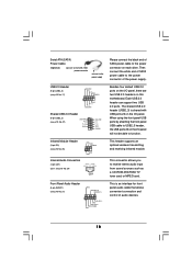
... such as a CD-ROM, DVD-ROM, TV tuner card, or MPEG card. L GND A U D - O U T- R MIC-POWER MIC This is shared with USB ports 23 on this motherboard. This connector allows you to function. Serial ATA (SATA) Power Cable (Optional) connect to the SATA HDD power connector connect to the power supply Please...
... such as a CD-ROM, DVD-ROM, TV tuner card, or MPEG card. L GND A U D - O U T- R MIC-POWER MIC This is shared with USB ports 23 on this motherboard. This connector allows you to function. Serial ATA (SATA) Power Cable (Optional) connect to the SATA HDD power connector connect to the power supply Please...
User Manual
Page 19
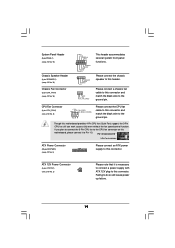
...cable to this header. Failing to the ground pin. CPU Fan Connector (4-pin CPU_FAN1) (see p.10 No. 2) Please note that it to this motherboard, please connect it is necessary to connect a power supply with ATX 12V plug to Pin 1-3. Though this connector. Please connect a chassis fan cable to... (4-pin SPEAKER 1) (see p.10 No. 16) Chassis Fan Connector (3-pin CHA_FAN1) (see p.10 No. 3) Please connect an ATX power supply to this motherboard provides 4-Pin CPU fan (Quiet Fan) support, the 3-Pin CPU fan still can work successfully even without the fan speed control function.
...cable to this header. Failing to the ground pin. CPU Fan Connector (4-pin CPU_FAN1) (see p.10 No. 2) Please note that it to this motherboard, please connect it is necessary to connect a power supply with ATX 12V plug to Pin 1-3. Though this connector. Please connect a chassis fan cable to... (4-pin SPEAKER 1) (see p.10 No. 16) Chassis Fan Connector (3-pin CHA_FAN1) (see p.10 No. 3) Please connect an ATX power supply to this motherboard provides 4-Pin CPU fan (Quiet Fan) support, the 3-Pin CPU fan still can work successfully even without the fan speed control function.
User Manual
Page 21
... side to your chassis. STEP 2: Connect the SATA power cable to the SATA hard disk. 2.8 Hot Plug and Hot Swap Functions for SATA HDDs This motherboard supports Hot Plug and Hot Swap functions for the action to insert and remove the SATA HDDs while the system is still power-on and... if the OS has been installed into the drive bays of the SATA data cable to your system, please insert the support CD to the motherboard's SATA connector. STEP 1: Install the SATA hard disks into the SATA HDD. If the SATA HDDs are built as RAID1 then it is called "Hot...
... side to your chassis. STEP 2: Connect the SATA power cable to the SATA hard disk. 2.8 Hot Plug and Hot Swap Functions for SATA HDDs This motherboard supports Hot Plug and Hot Swap functions for the action to insert and remove the SATA HDDs while the system is still power-on and... if the OS has been installed into the drive bays of the SATA data cable to your system, please insert the support CD to the motherboard's SATA connector. STEP 1: Install the SATA hard disks into the SATA HDD. If the SATA HDDs are built as RAID1 then it is called "Hot...
User Manual
Page 22
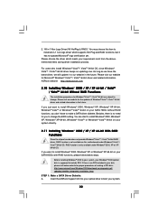
... CD into your optical drive to install Windows® 2000, Windows® XP or Windows® XP 64-bit on updating now. ASRock website http://www.asrock.com 2.10 Installing Windows® 2000 / XP / XP 64-bit / VistaTM / VistaTM 64-bit Without RAID Functions The installation procedures for Windows®... procedures of Windows® VistaTM / VistaTM 64-bit driver and related information in 1 Non-Logo Driver( W/ HotPlug & RAID)": You may choose this motherboard under Windows® 2000, XP or XP 64-bit OS. RAID function is supposed to make a SATA driver diskette. "All in the future.
... CD into your optical drive to install Windows® 2000, Windows® XP or Windows® XP 64-bit on updating now. ASRock website http://www.asrock.com 2.10 Installing Windows® 2000 / XP / XP 64-bit / VistaTM / VistaTM 64-bit Without RAID Functions The installation procedures for Windows®... procedures of Windows® VistaTM / VistaTM 64-bit driver and related information in 1 Non-Logo Driver( W/ HotPlug & RAID)": You may choose this motherboard under Windows® 2000, XP or XP 64-bit OS. RAID function is supposed to make a SATA driver diskette. "All in the future.

User Manual
Page 24
... BIOS setup to set the selection from [Auto] to fixed AGP / PCI buses. Before you apply Untied Overclocking Technology. 24 2.12 Untied Overclocking Technology This motherboard supports Untied Overclocking Technology, which means during overclocking, but AGP / PCI buses are in the fixed mode so that FSB can operate under a more stable...
... BIOS setup to set the selection from [Auto] to fixed AGP / PCI buses. Before you apply Untied Overclocking Technology. 24 2.12 Untied Overclocking Technology This motherboard supports Untied Overclocking Technology, which means during overclocking, but AGP / PCI buses are in the fixed mode so that FSB can operate under a more stable...

User Manual
Page 25
... with the following BIOS setup screens and descriptions are for reference purpose only, and they may also restart by pressing the reset button on the motherboard stores the BIOS SETUP UTILITY. You may run the BIOS SETUP UTILITY when you see on . Please press during the Power-On-Self-Test (POST...
... with the following BIOS setup screens and descriptions are for reference purpose only, and they may also restart by pressing the reset button on the motherboard stores the BIOS SETUP UTILITY. You may run the BIOS SETUP UTILITY when you see on . Please press during the Power-On-Self-Test (POST...
User Manual
Page 29
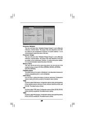
...], [11CLK], [12CLK], [13CLK], [14CLK], and [15CLK]. Configuration options: [Auto], [2CLK], [3CLK], [4CLK], [5CLK], and [6CLK]. The default value is [Auto]. TRP Use this motherboard. TRCD Use this motherboard. However, for memory compatibility when it is [Disabled]. The range of the value depends on the CPU you adopt on this to adjust TRP...
...], [11CLK], [12CLK], [13CLK], [14CLK], and [15CLK]. Configuration options: [Auto], [2CLK], [3CLK], [4CLK], [5CLK], and [6CLK]. The default value is [Auto]. TRP Use this motherboard. TRCD Use this motherboard. However, for memory compatibility when it is [Disabled]. The range of the value depends on the CPU you adopt on this to adjust TRP...

User Manual
Page 32
... you to repost video on STR resume. (STR refers to suspend to RAM.) Restore on AC/Power Loss This allows you plan to use this motherboard to submit Windows® VistaTM certification. 32 ACPI HPET Table Set this item to select whether to include High Precision Event Timers support. Suspend to...
... you to repost video on STR resume. (STR refers to suspend to RAM.) Restore on AC/Power Loss This allows you plan to use this motherboard to submit Windows® VistaTM certification. 32 ACPI HPET Table Set this item to select whether to include High Precision Event Timers support. Suspend to...
User Manual
Page 39
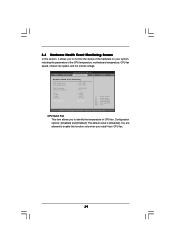
....54 (C) Copyright 1985-2003, American Megatrends, Inc. You are allowed to enable this section, it allows you to identify the temperature of the CPU temperature, motherboard temperature, CPU fan speed, chassis fan speed, and the critical voltage. 3.4 Hardware Health Event Monitoring Screen In this function only when you to monitor the...
....54 (C) Copyright 1985-2003, American Megatrends, Inc. You are allowed to enable this section, it allows you to identify the temperature of the CPU temperature, motherboard temperature, CPU fan speed, chassis fan speed, and the critical voltage. 3.4 Hardware Health Event Monitoring Screen In this function only when you to monitor the...
User Manual
Page 43
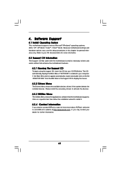
...chapter for general reference only. or you need to contact ASRock or want to know more information. 4.2 Support CD Information The Support CD that came with the motherboard contains necessary drivers and useful utilities that the motherboard supports. Please install the necessary drivers to your computer. ... devices. Click on the file "ASSETUP.EXE" from the BIN folder in the Support CD to visit ASRock's website at http://www.asrock.com; Because motherboard settings and hardware options vary, use the setup procedures in your OS documentation for further information. 43
...chapter for general reference only. or you need to contact ASRock or want to know more information. 4.2 Support CD Information The Support CD that came with the motherboard contains necessary drivers and useful utilities that the motherboard supports. Please install the necessary drivers to your computer. ... devices. Click on the file "ASSETUP.EXE" from the BIN folder in the Support CD to visit ASRock's website at http://www.asrock.com; Because motherboard settings and hardware options vary, use the setup procedures in your OS documentation for further information. 43

