
RAID Installation Guide
Page 2
.... RAID 0 (Data Striping) RAID 0 is equipped with two SATA / SATAII ports, you may choose to use RAID 0, RAID 1, or JBOD function with your motherboard is called data mirroring that optimizes two identical hard disk drives to the SATA / SATAII HDDs amount you may choose to use RAID 0, RAID 1, RAID... 0+1, JBOD, or RAID 5 function with your motherboard is called data striping that copies and maintains an identical image of using NVIDIA RAID Utility under BIOS environment. If your...
.... RAID 0 (Data Striping) RAID 0 is equipped with two SATA / SATAII ports, you may choose to use RAID 0, RAID 1, or JBOD function with your motherboard is called data mirroring that optimizes two identical hard disk drives to the SATA / SATAII HDDs amount you may choose to use RAID 0, RAID 1, RAID... 0+1, JBOD, or RAID 5 function with your motherboard is called data striping that copies and maintains an identical image of using NVIDIA RAID Utility under BIOS environment. If your...

RAID Installation Guide
Page 5
...selection appears. Then press any key to continue Please insert a floppy diskette into your optical drive to boot your system. (There are two ASRock Support CD in your disk, please visit the below website for proper procedures of system boot-up, press key, and then a window ... driver diskette [YN]?", press . Before installing Windows® 2000 to your system, your Windows® 2000 optical disk is no SP4 included in the motherboard gift box pack, please choose the one for Windows2000/XP 2. D. 1.3 Installing Windows® 2000 / XP / XP 64-bit / VistaTM / VistaTM...
...selection appears. Then press any key to continue Please insert a floppy diskette into your optical drive to boot your system. (There are two ASRock Support CD in your disk, please visit the below website for proper procedures of system boot-up, press key, and then a window ... driver diskette [YN]?", press . Before installing Windows® 2000 to your system, your Windows® 2000 optical disk is no SP4 included in the motherboard gift box pack, please choose the one for Windows2000/XP 2. D. 1.3 Installing Windows® 2000 / XP / XP 64-bit / VistaTM / VistaTM...
RAID Installation Guide
Page 7
... guide in the following path in the Support CD: .. \ RAID Installation Guide 7 Please refer to continue the installation. page, please insert the ASRock Support CD into the optical drive again to the BIOS RAID installation guide part of the document in the following path in our Support CD... bottom to [RAID]. If you install Windows® VistaTM / Windows® VistaTM 64-bit on IDE HDDs and want to [RAID] in the motherboard gift box pack, please choose the one for proper configuration. B. Before you start to configure RAID function, you need to set up "SATA Operation ...
... guide in the following path in the Support CD: .. \ RAID Installation Guide 7 Please refer to continue the installation. page, please insert the ASRock Support CD into the optical drive again to the BIOS RAID installation guide part of the document in the following path in our Support CD... bottom to [RAID]. If you install Windows® VistaTM / Windows® VistaTM 64-bit on IDE HDDs and want to [RAID] in the motherboard gift box pack, please choose the one for proper configuration. B. Before you start to configure RAID function, you need to set up "SATA Operation ...

RAID Installation Guide
Page 12
... to use NVRAIDMAN to below : - RAID 1: Mirroring - JBOD: Spanning - If you plan to use RAID 0, RAID 1, or JBOD function with your motherboard provides in advance and follow the instruction in this section, we take RAID 0 for example to show you may choose to create RAID arrays. Please... refer to create RAID 0 (Striping). If your motherboard. If your motherboard is equipped with four SATA / SATAII ports, you how to use RAID 0, RAID 1, RAID 0+1, JBOD, or RAID 5 function with your...
... to use NVRAIDMAN to below : - RAID 1: Mirroring - JBOD: Spanning - If you plan to use RAID 0, RAID 1, or JBOD function with your motherboard provides in advance and follow the instruction in this section, we take RAID 0 for example to show you may choose to create RAID arrays. Please... refer to create RAID 0 (Striping). If your motherboard. If your motherboard is equipped with four SATA / SATAII ports, you how to use RAID 0, RAID 1, RAID 0+1, JBOD, or RAID 5 function with your...

User Manual
Page 2
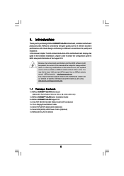
..., USA ONLY The Lithium battery adopted on this motherboard contains Perchlorate, a toxic substance controlled in Perchlorate Best Management Practices (BMP) regulations passed by the purchaser for any errors or omissions that may apply, see www.dtsc.ca.gov/hazardouswaste/perchlorate" ASRock Website: http://www.asrock.com 2 With respect to the contents of this...
..., USA ONLY The Lithium battery adopted on this motherboard contains Perchlorate, a toxic substance controlled in Perchlorate Best Management Practices (BMP) regulations passed by the purchaser for any errors or omissions that may apply, see www.dtsc.ca.gov/hazardouswaste/perchlorate" ASRock Website: http://www.asrock.com 2 With respect to the contents of this...

User Manual
Page 3
Introduction 5 1.1 Package Contents 5 1.2 Specifications 6 1.3 Motherboard Layout 9 1.4 ASRock 6CH_DVI I/O 10 2 . Installation 11 Pre-installation Precautions 11 2.1 CPU Installation 12 2.2 Installation of CPU Fan and Heatsink 12 2.3 Installation of Memory Modules (DIMM 13 2.4 Expansion ...
Introduction 5 1.1 Package Contents 5 1.2 Specifications 6 1.3 Motherboard Layout 9 1.4 ASRock 6CH_DVI I/O 10 2 . Installation 11 Pre-installation Precautions 11 2.1 CPU Installation 12 2.2 Installation of CPU Fan and Heatsink 12 2.3 Installation of Memory Modules (DIMM 13 2.4 Expansion ...
User Manual
Page 5
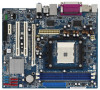
... support related to change without further notice. In this motherboard, please visit our website for purchasing ASRock K8N68PV-GLAN motherboard, a reliable motherboard produced under ASRock's consistently stringent quality control. www.asrock.com/support/index.asp 1.1 Package Contents 1 x ASRock K8N68PV-GLAN Motherboard (Micro ATX Form Factor: 9.6-in x 8.0-in, 24.4 cm x 20.3 cm) 1 x ASRock K8N68PV-GLAN Quick Installation Guide 2 x ASRock K8N68PV-GLAN Support CD 1 x Ultra ATA 66/100/133 IDE...
... support related to change without further notice. In this motherboard, please visit our website for purchasing ASRock K8N68PV-GLAN motherboard, a reliable motherboard produced under ASRock's consistently stringent quality control. www.asrock.com/support/index.asp 1.1 Package Contents 1 x ASRock K8N68PV-GLAN Motherboard (Micro ATX Form Factor: 9.6-in x 8.0-in, 24.4 cm x 20.3 cm) 1 x ASRock K8N68PV-GLAN Quick Installation Guide 2 x ASRock K8N68PV-GLAN Support CD 1 x Ultra ATA 66/100/133 IDE...

User Manual
Page 8
...While CPU overheat is subject to SATAII connector, please read "Untied Overclocking Technology" on page 32 for the chipset adopted on this motherboard offers stepless control, it back again. Please check NVIDIA® website for further information. 6. Before you install the PC system...will automatically shutdown. Before installing SATAII hard disk to change. You can support DVI/HDCP and HDMI format signal. Although this motherboard can also connect SATA hard disk to perform over-clocking. CAUTION! 1. DVI to HDMI adapter is not recommended to SATAII connector...
...While CPU overheat is subject to SATAII connector, please read "Untied Overclocking Technology" on page 32 for the chipset adopted on this motherboard offers stepless control, it back again. Please check NVIDIA® website for further information. 6. Before you install the PC system...will automatically shutdown. Before installing SATAII hard disk to change. You can support DVI/HDCP and HDMI format signal. Although this motherboard can also connect SATA hard disk to perform over-clocking. CAUTION! 1. DVI to HDMI adapter is not recommended to SATAII connector...

User Manual
Page 9
1.3 Motherboard Layout 1 23 4 5 67 8 20.3cm (8.0-in) 1 PS2_USB_PW1 ATX12V1 CPU_FAN1 PS2 Mouse PS2 Keyboard DDR400 1 COM1 DDR1 (64 bit, 184-pinFmoSdBul8e)00 DDR2 (64 bit, 184-... 2.0 T: USB0 B: USB1 Top: RJ-45 USB 2.0 T: USB2 B: USB3 HDCP DVI LAN PHY Gigabit LAN CD1 RAID AUDIO CODEC PCIE2 1 HD_AUDIO1 FLOPPY1 PCI EXPRESS SATAII PCIE1 K8N68PV-GLAN CMOS BATTERY PCI1 RoHS CLRCMOS1 1 CHA_FAN1 SATAII_4 (PORT 3) SATAII_3 (PORT 2) SATAII_2 (PORT 1) PCI2 SPEAKER1 1 4Mb BIOS PLED PWRBTN 1 PANEL 1 HDLED RESET NVIDIA GeForce 7050 / nForce...
1.3 Motherboard Layout 1 23 4 5 67 8 20.3cm (8.0-in) 1 PS2_USB_PW1 ATX12V1 CPU_FAN1 PS2 Mouse PS2 Keyboard DDR400 1 COM1 DDR1 (64 bit, 184-pinFmoSdBul8e)00 DDR2 (64 bit, 184-... 2.0 T: USB0 B: USB1 Top: RJ-45 USB 2.0 T: USB2 B: USB3 HDCP DVI LAN PHY Gigabit LAN CD1 RAID AUDIO CODEC PCIE2 1 HD_AUDIO1 FLOPPY1 PCI EXPRESS SATAII PCIE1 K8N68PV-GLAN CMOS BATTERY PCI1 RoHS CLRCMOS1 1 CHA_FAN1 SATAII_4 (PORT 3) SATAII_3 (PORT 2) SATAII_2 (PORT 1) PCI2 SPEAKER1 1 4Mb BIOS PLED PWRBTN 1 PANEL 1 HDLED RESET NVIDIA GeForce 7050 / nForce...

User Manual
Page 11
...K8N68PV-GLAN is detached from the wall socket before you uninstall any component, ensure that the power is switched off or the power cord is a Micro ATX form factor (9.6-in x 8.0-in the bag that the motherboard fits into the screw holes to secure the motherboard to static electricity, NEVER place your chassis to the motherboard...a grounded wrist strap or touch a safety grounded object before you install the motherboard, study the configuration of the following precautions before touching any motherboard settings. Hold components by the edges and do not over-tighten the screws!...
...K8N68PV-GLAN is detached from the wall socket before you uninstall any component, ensure that the power is switched off or the power cord is a Micro ATX form factor (9.6-in x 8.0-in the bag that the motherboard fits into the screw holes to secure the motherboard to static electricity, NEVER place your chassis to the motherboard...a grounded wrist strap or touch a safety grounded object before you install the motherboard, study the configuration of the following precautions before touching any motherboard settings. Hold components by the edges and do not over-tighten the screws!...

User Manual
Page 12
... Fan and Heatsink After you push down the socket lever to the CPU FAN connector (CPU_FAN1, see Page 9, No. 7). Carefully insert the CPU into this motherboard, it fits in good contact with a small triangle. 2.1 CPU Installation Step 1. Step 2. Step 4. Make sure that the CPU corner with the golden triangle matches the...
... Fan and Heatsink After you push down the socket lever to the CPU FAN connector (CPU_FAN1, see Page 9, No. 7). Carefully insert the CPU into this motherboard, it fits in good contact with a small triangle. 2.1 CPU Installation Step 1. Step 2. Step 4. Make sure that the CPU corner with the golden triangle matches the...

User Manual
Page 13
... DIMM only fits in place and the DIMM is equipped with two 184-pin DDR (Double Data Rate) DIMM slots. Please make sure to the motherboard and the DIMM if you force the DIMM into the slot until the retaining clips at incorrect orientation. Step 1. Step 3. It will cause permanent damage... at both ends fully snap back in one correct orientation. Unlock a DIMM slot by pressing the retaining clips outward. 2.3 Installation of Memory Modules (DIMM) This motherboard is properly seated. 13
... DIMM only fits in place and the DIMM is equipped with two 184-pin DDR (Double Data Rate) DIMM slots. Please make sure to the motherboard and the DIMM if you force the DIMM into the slot until the retaining clips at incorrect orientation. Step 1. Step 3. It will cause permanent damage... at both ends fully snap back in one correct orientation. Unlock a DIMM slot by pressing the retaining clips outward. 2.3 Installation of Memory Modules (DIMM) This motherboard is properly seated. 13

User Manual
Page 14
...graphics cards. PCIE2 (PCIE x1 slot) is used for PCI Express cards with x1 lane width cards, such as Gigabit LAN card, SATA2 card and ASRock PCIE_DE card. Remove the bracket facing the slot that have the 32-bit PCI interface. Please read the documentation of the expansion card and make... sure that the power supply is switched off or the power cord is completely seated on this motherboard. Step 3. Fasten the card to the chassis with the slot and press firmly until the card is unplugged. PCI slots: PCI slots are 2 PCI ...
...graphics cards. PCIE2 (PCIE x1 slot) is used for PCI Express cards with x1 lane width cards, such as Gigabit LAN card, SATA2 card and ASRock PCIE_DE card. Remove the bracket facing the slot that have the 32-bit PCI interface. Please read the documentation of the expansion card and make... sure that the power supply is switched off or the power cord is completely seated on this motherboard. Step 3. Fasten the card to the chassis with the slot and press firmly until the card is unplugged. PCI slots: PCI slots are 2 PCI ...

User Manual
Page 15
...enable dual monitor feature, please follow the below steps: 1. Connect the D-Sub monitor cable to the VGA/D-Sub port on VGA card to this motherboard after your computer. If you have installed onboard VGA driver from our support CD to your system already, you haven't installed onboard VGA driver yet... support (DVI-D and D-Sub), you can freely enjoy the benefits of dual monitor function provided by VGA/DVI-D and VGA/D-Sub ports with this motherboard. VGA/DVI-D port VGA/D-Sub port 2. Connect the DVI-D monitor cable to support dual VGA output so that DVI-D and D-sub can easily ...
...enable dual monitor feature, please follow the below steps: 1. Connect the D-Sub monitor cable to the VGA/D-Sub port on VGA card to this motherboard after your computer. If you have installed onboard VGA driver from our support CD to your system already, you haven't installed onboard VGA driver yet... support (DVI-D and D-Sub), you can freely enjoy the benefits of dual monitor function provided by VGA/DVI-D and VGA/D-Sub ports with this motherboard. VGA/DVI-D port VGA/D-Sub port 2. Connect the DVI-D monitor cable to support dual VGA output so that DVI-D and D-sub can easily ...

User Manual
Page 16
...and select the "Display Settings" tab so that you use multiple monitors with your primary monitor, and then select "Primary". Surround Display Feature This motherboard supports surround display upgrade. Enter "Share Memory" option to adjust the memory capability to [32MB], [64MB], [128MB] or [256MB] to ... will disable VGA/D-Sub function when the add-on the I /O panel of the system memory. Click "Extend my Windows desktop onto this motherboard. 3. Install the NVIDIA® PCI Express VGA card to be designated as appropriate for the diaplay icon identified by the number 2. F....
...and select the "Display Settings" tab so that you use multiple monitors with your primary monitor, and then select "Primary". Surround Display Feature This motherboard supports surround display upgrade. Enter "Share Memory" option to adjust the memory capability to [32MB], [64MB], [128MB] or [256MB] to ... will disable VGA/D-Sub function when the add-on the I /O panel of the system memory. Click "Extend my Windows desktop onto this motherboard. 3. Install the NVIDIA® PCI Express VGA card to be designated as appropriate for the diaplay icon identified by the number 2. F....

User Manual
Page 17
... below . D. Please refer to use HDCP function with this monitor". HDCP is supported with DVI-D port on this motherboard. Click the items "This is my main monitor" and "Extend the desktop onto this motherboard, you need to protect the integrity of content as a monitor, television or projector. To use . In other words...
... below . D. Please refer to use HDCP function with this monitor". HDCP is supported with DVI-D port on this motherboard. Click the items "This is my main monitor" and "Extend the desktop onto this motherboard, you need to protect the integrity of content as a monitor, television or projector. To use . In other words...

User Manual
Page 18
...Enter BIOS SETUP UTILITY Advanced screen Chipset Configuration. B. Step 3: Reboot your system. After HDMI audio driver is not bundled with this motherboard can support DVI/HDCP and HDMI format signal. Therefore, the onboard audio jack will output the audio signal through HDMI audio. Enter...B. Step 2: Install HDMI audio driver to the adapter vendor for the chipset adopted on this motherboard, please refer to your system. A. Install "Onboard HDMI HD Audio Driver" from ASRock Support CD to the OS you install. Please follow below steps to enable HDMI audio function ...
...Enter BIOS SETUP UTILITY Advanced screen Chipset Configuration. B. Step 3: Reboot your system. After HDMI audio driver is not bundled with this motherboard can support DVI/HDCP and HDMI format signal. Therefore, the onboard audio jack will output the audio signal through HDMI audio. Enter...B. Step 2: Install HDMI audio driver to the adapter vendor for the chipset adopted on this motherboard, please refer to your system. A. Install "Onboard HDMI HD Audio Driver" from ASRock Support CD to the OS you install. Please follow below steps to enable HDMI audio function ...

User Manual
Page 20
... Data Cable (Optional) Serial ATA (SATA) Power Cable (Optional) connect to the SATA HDD power connector connect to the power connector on the motherboard. Placing jumper caps over these headers and connectors. Primary IDE connector (Blue) (39-pin IDE1, see p.9, No. 14) These four Serial ATAII... (PORT 1): see p.9, No. 13) (SATAII_3 (PORT 2): see p.9, No. 12) (SATAII_4 (PORT 3): see p.9 No. 9) PIN1 IDE1 connect the blue end to the motherboard connect the black end to the IDE devices 80-conductor ATA 66/100/133 cable Note: Please refer to the instruction of SATA power cable...
... Data Cable (Optional) Serial ATA (SATA) Power Cable (Optional) connect to the SATA HDD power connector connect to the power connector on the motherboard. Placing jumper caps over these headers and connectors. Primary IDE connector (Blue) (39-pin IDE1, see p.9, No. 14) These four Serial ATAII... (PORT 1): see p.9, No. 13) (SATAII_3 (PORT 2): see p.9, No. 12) (SATAII_4 (PORT 3): see p.9 No. 9) PIN1 IDE1 connect the blue end to the motherboard connect the black end to the IDE devices 80-conductor ATA 66/100/133 cable Note: Please refer to the instruction of SATA power cable...

User Manual
Page 21
... the Hot Plug detection function for the front panel audio cable that allows convenient connection and control of audio devices. This is an interface for ASRock DeskExpress. This connector allows you to receive stereo audio input from sound sources such as a CD-ROM, DVD-ROM, TV tuner card, or MPEG card... USB_PWR P-7 P+7 GND DUMMY 1 GND P+6 P-6 USB_PWR USB_PWR P-5 P+5 GND DUMMY 1 GND P+4 P-4 USB_PWR Besides four default USB 2.0 ports on the I/O panel, there are four USB 2.0 headers on this motherboard. Each USB 2.0 header can support two USB 2.0 ports.
... the Hot Plug detection function for the front panel audio cable that allows convenient connection and control of audio devices. This is an interface for ASRock DeskExpress. This connector allows you to receive stereo audio input from sound sources such as a CD-ROM, DVD-ROM, TV tuner card, or MPEG card... USB_PWR P-7 P+7 GND DUMMY 1 GND P+6 P-6 USB_PWR USB_PWR P-5 P+5 GND DUMMY 1 GND P+4 P-4 USB_PWR Besides four default USB 2.0 ports on the I/O panel, there are four USB 2.0 headers on this motherboard. Each USB 2.0 header can support two USB 2.0 ports.

User Manual
Page 23
Though this motherboard provides 4-Pin CPU fan (Quiet Fan) support, the 3-Pin CPU fan still can still work successfully even ...failure. To use the 20-pin ATX power supply, please plug your power supply along with ATX 12V plug to this motherboard provides 24-pin ATX power connector, 12 24 it can work if you plan to connect the 3-Pin CPU fan to... the CPU fan connector on this motherboard, please connect it is necessary to connect a power supply with Pin 1 and Pin 13. 20-Pin ATX Power Supply Installation ...
Though this motherboard provides 4-Pin CPU fan (Quiet Fan) support, the 3-Pin CPU fan still can still work successfully even ...failure. To use the 20-pin ATX power supply, please plug your power supply along with ATX 12V plug to this motherboard provides 24-pin ATX power connector, 12 24 it can work if you plan to connect the 3-Pin CPU fan to... the CPU fan connector on this motherboard, please connect it is necessary to connect a power supply with Pin 1 and Pin 13. 20-Pin ATX Power Supply Installation ...

