User Manual
Page 1
MOTHERBOARD K8 Combo-Z User Manual Version 1.0 Published July 2004 Copyright©2004 ASRock INC. All rights reserved. 1
MOTHERBOARD K8 Combo-Z User Manual Version 1.0 Published July 2004 Copyright©2004 ASRock INC. All rights reserved. 1
User Manual
Page 3
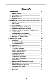
... Setup 17 2.7 Onboard Headers and Connectors 18 2.8 Serial ATA (SATA) Hard Disks Installation 21 2.9 Making An SATA Driver Diskette 21 3. Introduction 5 1.1 Package Contents 5 1.2 Specifications 6 1.3 Motherboard Layout 9 1.4 ASRock 8CH I/O 10 2. BIOS SETUP UTILITY 22 3.1 Introduction 22 3.1.1 BIOS Menu Bar 22 3.1.2 Navigation Keys 23 3.2 Main Screen 23 3.3 Advanced Screen 24 3.3.1 CPU Configuration 24 3.3.2 Chipset...
... Setup 17 2.7 Onboard Headers and Connectors 18 2.8 Serial ATA (SATA) Hard Disks Installation 21 2.9 Making An SATA Driver Diskette 21 3. Introduction 5 1.1 Package Contents 5 1.2 Specifications 6 1.3 Motherboard Layout 9 1.4 ASRock 8CH I/O 10 2. BIOS SETUP UTILITY 22 3.1 Introduction 22 3.1.1 BIOS Menu Bar 22 3.1.2 Navigation Keys 23 3.2 Main Screen 23 3.3 Advanced Screen 24 3.3.1 CPU Configuration 24 3.3.2 Chipset...
User Manual
Page 5
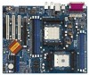
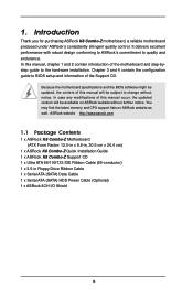
.... 1. Introduction Thank you for purchasing ASRock K8 Combo-Z motherboard, a reliable motherboard produced under ASRock's consistently stringent quality control. Because the motherboard specifications and the BIOS software might be available on ASRock website as well. ASRock website http://www.asrock.com 1.1 Package Contents 1 x ASRock K8 Combo-Z Motherboard (ATX Form Factor: 12.0-in x 9.6-in, 30.5 cm x 24.4 cm) 1 x ASRock K8 Combo-Z Quick Installation Guide 1 x ASRock K8 Combo-Z Support CD 1 x Ultra ATA 66...
.... 1. Introduction Thank you for purchasing ASRock K8 Combo-Z motherboard, a reliable motherboard produced under ASRock's consistently stringent quality control. Because the motherboard specifications and the BIOS software might be available on ASRock website as well. ASRock website http://www.asrock.com 1.1 Package Contents 1 x ASRock K8 Combo-Z Motherboard (ATX Form Factor: 12.0-in x 9.6-in, 30.5 cm x 24.4 cm) 1 x ASRock K8 Combo-Z Quick Installation Guide 1 x ASRock K8 Combo-Z Support CD 1 x Ultra ATA 66...
User Manual
Page 6
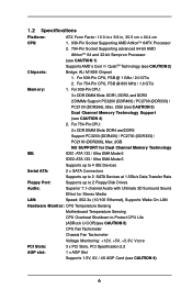
... Sound Effect for Stereo Media LAN: Speed: 802.3u (10/100 Ethernet), Supports Wake-On-LAN Hardware Monitor: CPU Temperature Sensing Motherboard Temperature Sensing CPU Overheat Shutdown to Protect CPU Life (ASRock U-COP)(see CAUTION 5) CPU Fan Tachometer Chassis Fan Tachometer Voltage Monitoring: +12V, +5V, +3.3V, Vcore PCI Slots: 3 x PCI Slots, PCI...
... Sound Effect for Stereo Media LAN: Speed: 802.3u (10/100 Ethernet), Supports Wake-On-LAN Hardware Monitor: CPU Temperature Sensing Motherboard Temperature Sensing CPU Overheat Shutdown to Protect CPU Life (ASRock U-COP)(see CAUTION 5) CPU Fan Tachometer Chassis Fan Tachometer Voltage Monitoring: +12V, +5V, +3.3V, Vcore PCI Slots: 3 x PCI Slots, PCI...
User Manual
Page 8
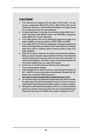
.... To improve heat dissipation, remember to spray thermal grease between the CPU and the heatsink when you install a 939-Pin CPU into this motherboard, please refer to page 14 for USB 2.0 works fine under Windows system. See APPENDIX on page 14 for proper connection. 9. Before you... Channel Memory Technology, make sure to read the installation guide of memory modules on page 39 to perform over-clocking. For microphone input, this motherboard supports both of the system or damage the CPU. 8 CAUTION! 1. You may not work properly under Microsoft® Windows® 98/ ...
.... To improve heat dissipation, remember to spray thermal grease between the CPU and the heatsink when you install a 939-Pin CPU into this motherboard, please refer to page 14 for USB 2.0 works fine under Windows system. See APPENDIX on page 14 for proper connection. 9. Before you... Channel Memory Technology, make sure to read the installation guide of memory modules on page 39 to perform over-clocking. For microphone input, this motherboard supports both of the system or damage the CPU. 8 CAUTION! 1. You may not work properly under Microsoft® Windows® 98/ ...
User Manual
Page 11
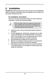
...an ATX form factor (12.0-in x 9.6-in the bag that comes with the component. 5. Installation K8 Combo-Z is detached from the wall socket before you install motherboard components or change any component. 2. When placing screws into it on the carpet or the like. ...Hold components by the edges and do so may damage the motherboard. 11 Pre-installation Precautions Take note of your motherboard directly on a grounded antistatic pad or in , 30.5 cm x 24.4 cm) motherboard. Before you install the motherboard, study the configuration of the following precautions before you handle ...
...an ATX form factor (12.0-in x 9.6-in the bag that comes with the component. 5. Installation K8 Combo-Z is detached from the wall socket before you install motherboard components or change any component. 2. When placing screws into it on the carpet or the like. ...Hold components by the edges and do so may damage the motherboard. 11 Pre-installation Precautions Take note of your motherboard directly on a grounded antistatic pad or in , 30.5 cm x 24.4 cm) motherboard. Before you install the motherboard, study the configuration of the following precautions before you handle ...
User Manual
Page 12
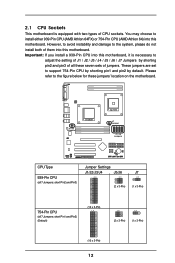
... 7 Jumpers: short Pin1 and Pin2) (Default) (10 x 3-Pin) 1_2 1_2 1_2 (2 x 3-Pin) (1 x 3-Pin) (10 x 3-Pin) 12 Important: If you install a 939-Pin CPU into this motherboard, it is equipped with two types of CPU sockets. Please refer to the figure below for these seven sets of jumpers. J4 Jumpers CPU Type... and Pin3) Jumper Settings J1/J2/J3/J4 J5/J6 J7 2_3 2_3 2_3 (2 x 3-Pin) (1 x 3-Pin) 754-Pin CPU (all these jumpers' location on the motherboard. You may choose to install either 939-Pin CPU (AMD Athlon 64FX) or 754-Pin CPU (AMD Athlon 64) into this...
... 7 Jumpers: short Pin1 and Pin2) (Default) (10 x 3-Pin) 1_2 1_2 1_2 (2 x 3-Pin) (1 x 3-Pin) (10 x 3-Pin) 12 Important: If you install a 939-Pin CPU into this motherboard, it is equipped with two types of CPU sockets. Please refer to the figure below for these seven sets of jumpers. J4 Jumpers CPU Type... and Pin3) Jumper Settings J1/J2/J3/J4 J5/J6 J7 2_3 2_3 2_3 (2 x 3-Pin) (1 x 3-Pin) 754-Pin CPU (all these jumpers' location on the motherboard. You may choose to install either 939-Pin CPU (AMD Athlon 64FX) or 754-Pin CPU (AMD Athlon 64) into this...
User Manual
Page 13
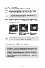
... that the CPU and the heatsink are securely fastened and in place, press it firmly on the socket while you install the CPU into this motherboard. 2.3 Installation of the CPU fan and the heatsink. 13 The lever clicks on the side tab to avoid bending of the pins. Unlock the socket... heat. Step 2. Then connect the CPU fan to the system, please do not install both of 939-Pin CPU and 754-Pin CPU into this motherboard, it fits in one correct orientation. 2.2 CPU Installation Step 1. When the CPU is locked. Lever 90° Up Socket Corner CPU Golden Triangle STEP 1: Lift...
... that the CPU and the heatsink are securely fastened and in place, press it firmly on the socket while you install the CPU into this motherboard. 2.3 Installation of the CPU fan and the heatsink. 13 The lever clicks on the side tab to avoid bending of the pins. Unlock the socket... heat. Step 2. Then connect the CPU fan to the system, please do not install both of 939-Pin CPU and 754-Pin CPU into this motherboard, it fits in one correct orientation. 2.2 CPU Installation Step 1. When the CPU is locked. Lever 90° Up Socket Corner CPU Golden Triangle STEP 1: Lift...
User Manual
Page 14
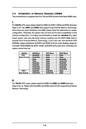
... up ! Besides, please do not install 3 DDR DIMMs into DDR1, DDR2 and DDR3 slots (see Page 9, No. 5). I. For best compatibility of Memory Modules (DIMM) This motherboard is highly recommended to install two identical (the same brand, speed, size and chip-type) memory modules into the DDR DIMM slots to activate Dual...
... up ! Besides, please do not install 3 DDR DIMMs into DDR1, DDR2 and DDR3 slots (see Page 9, No. 5). I. For best compatibility of Memory Modules (DIMM) This motherboard is highly recommended to install two identical (the same brand, speed, size and chip-type) memory modules into the DDR DIMM slots to activate Dual...
User Manual
Page 15
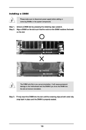
.... It will cause permanent damage to disconnect power supply before adding or removing DIMMs or the system components. Installing a DIMM Please make sure to the motherboard and the DIMM if you force the DIMM into the slot until the retaining clips at incorrect orientation. Step 3. Step 2.
.... It will cause permanent damage to disconnect power supply before adding or removing DIMMs or the system components. Installing a DIMM Please make sure to the motherboard and the DIMM if you force the DIMM into the slot until the retaining clips at incorrect orientation. Step 3. Step 2.
User Manual
Page 16
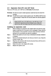
... Keep the screws for the card before you intend to use. Step 5. PCI Slots: PCI slots are 3 PCI slots, and 1 AGP slot on K8 Combo-Z motherboard. Before installing the expansion card, please make necessary hardware settings for later use a 3.3V AGP card on the slot. Step 4. Fasten the card to... completely seated on the AGP slot of your motherboard is used to install expansion cards that have the 32-bit PCI interface. For the voltage information of this motherboard! AGP slot: The AGP slot is already installed in a chassis). The ASRock AGP slot has a special design of the ...
... Keep the screws for the card before you intend to use. Step 5. PCI Slots: PCI slots are 3 PCI slots, and 1 AGP slot on K8 Combo-Z motherboard. Before installing the expansion card, please make necessary hardware settings for later use a 3.3V AGP card on the slot. Step 4. Fasten the card to... completely seated on the AGP slot of your motherboard is used to install expansion cards that have the 32-bit PCI interface. For the voltage information of this motherboard! AGP slot: The AGP slot is already installed in a chassis). The ASRock AGP slot has a special design of the ...
User Manual
Page 18
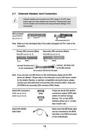
... and performance, please connect your IDE device vendor for internal storage devices. Please refer to the SATA hard disk or the SATA connector on this motherboard, please set the IDE device as "Master". Serial ATA Connectors (SATA1: see p.9, No. 21) (SATA2: see p.9, No. 17) Pin1 FLOPPY1... red-striped side of the cable is plugged into Pin1 side of the SATA data cable can be connected to the instruction of the motherboard! Placing jumper caps over these headers and connectors. 2.7 Onboard Headers and Connectors Onboard headers and connectors are NOT jumpers. Primary IDE connector...
... and performance, please connect your IDE device vendor for internal storage devices. Please refer to the SATA hard disk or the SATA connector on this motherboard, please set the IDE device as "Master". Serial ATA Connectors (SATA1: see p.9, No. 21) (SATA2: see p.9, No. 17) Pin1 FLOPPY1... red-striped side of the cable is plugged into Pin1 side of the SATA data cable can be connected to the instruction of the motherboard! Placing jumper caps over these headers and connectors. 2.7 Onboard Headers and Connectors Onboard headers and connectors are NOT jumpers. Primary IDE connector...
User Manual
Page 21
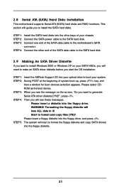
... driver diskette [YN]?", press . Formatting the floppy diskette will start the OS installation. Please select CDROM as the boot device. Start to the motherboard's SATA connector. This section will need to make an SATA driver diskette before you want to install the SATA hard disks. WARNING! STEP 5: ...The system will lose ALL data in it! STEP 1: Insert the ASRock Support CD into the floppy drive. STEP 2: During POST at the beginning of your SATA HDDs, you will guide you see these messages, ...
... driver diskette [YN]?", press . Formatting the floppy diskette will start the OS installation. Please select CDROM as the boot device. Start to the motherboard's SATA connector. This section will need to make an SATA driver diskette before you want to install the SATA hard disks. WARNING! STEP 5: ...The system will lose ALL data in it! STEP 1: Insert the ASRock Support CD into the floppy drive. STEP 2: During POST at the beginning of your SATA HDDs, you will guide you see these messages, ...
User Manual
Page 22
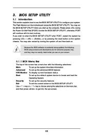
... press to enter the BIOS SETUP UTILITY after POST, restart the system by pressing + + , or by turning the system off and then back on the motherboard stores the BIOS SETUP UTILITY. Please press during the Power-On-Self-Test (POST) to enter the BIOS SETUP UTILITY, otherwise, POST will continue with...
... press to enter the BIOS SETUP UTILITY after POST, restart the system by pressing + + , or by turning the system off and then back on the motherboard stores the BIOS SETUP UTILITY. Please press during the Power-On-Self-Test (POST) to enter the BIOS SETUP UTILITY, otherwise, POST will continue with...
User Manual
Page 24
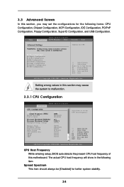
3.3 Advanced Screen In this motherboard. CPU Configuration Chipset Configuration ACPI Configuration IDE Configuration PCIPnP Configuration Floppy Configuration SuperIO Configuration USB Configuration Options for CPU Select Screen Select Item Enter Go ...
3.3 Advanced Screen In this motherboard. CPU Configuration Chipset Configuration ACPI Configuration IDE Configuration PCIPnP Configuration Floppy Configuration SuperIO Configuration USB Configuration Options for CPU Select Screen Select Item Enter Go ...
User Manual
Page 34
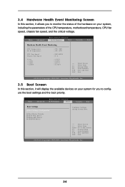
Select Screen Select Item Enter Go to monitor the status of the CPU temperature, motherboard temperature, CPU fan speed, chassis fan speed, and the critical voltage. 3.4 Hardware Health Event Monitoring Screen In this section, it allows you to configure the ...
Select Screen Select Item Enter Go to monitor the status of the CPU temperature, motherboard temperature, CPU fan speed, chassis fan speed, and the critical voltage. 3.4 Hardware Health Event Monitoring Screen In this section, it allows you to configure the ...
User Manual
Page 38
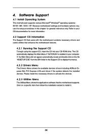
...4.2.2 Drivers Menu The Drivers Menu shows the available devices drivers including ASRock Express GbL PCI Express LAN card driver if the system detects the installed devices. Software Support 4.1 Install Operating System This motherboard supports various Microsoft® Windows® operating systems: 98 SE /... Menu The Utilities Menu shows the applications software that enhance the motherboard features. 4.2.1 Running The Support CD To begin using the support CD, insert the CD into your computer. Because motherboard settings and hardware options vary, use the setup procedures in this...
...4.2.2 Drivers Menu The Drivers Menu shows the available devices drivers including ASRock Express GbL PCI Express LAN card driver if the system detects the installed devices. Software Support 4.1 Install Operating System This motherboard supports various Microsoft® Windows® operating systems: 98 SE /... Menu The Utilities Menu shows the applications software that enhance the motherboard features. 4.2.1 Running The Support CD To begin using the support CD, insert the CD into your computer. Because motherboard settings and hardware options vary, use the setup procedures in this...

