User Manual
Page 3
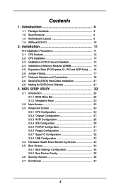
...Boot Settings Configuration 35 3.5.2 Boot Device Priority 35 3.6 Security Screen 36 3.7 Exit Screen 37 3 Installation 11 Pre-installation Precautions 11 2.1 CPU Sockets 12 2.2 CPU Installation 13 2.3 Installation of CPU Fan and Heatsink 13 2.4 Installation of Memory Modules (DIMM 14 2.5 Expansion Slots (PCI Express X1, PCI and AGP Slots) ..... 16 2.6 Jumpers Setup 17 2.7 Onboard Headers and Connectors 18 2.8 Serial ATA (SATA) Hard Disks Installation 21 2.9 Making An SATA Driver Diskette 21 3. Introduction 5 1.1 Package Contents 5 1.2 Specifications 6 1.3 Motherboard Layout...
...Boot Settings Configuration 35 3.5.2 Boot Device Priority 35 3.6 Security Screen 36 3.7 Exit Screen 37 3 Installation 11 Pre-installation Precautions 11 2.1 CPU Sockets 12 2.2 CPU Installation 13 2.3 Installation of CPU Fan and Heatsink 13 2.4 Installation of Memory Modules (DIMM 14 2.5 Expansion Slots (PCI Express X1, PCI and AGP Slots) ..... 16 2.6 Jumpers Setup 17 2.7 Onboard Headers and Connectors 18 2.8 Serial ATA (SATA) Hard Disks Installation 21 2.9 Making An SATA Driver Diskette 21 3. Introduction 5 1.1 Package Contents 5 1.2 Specifications 6 1.3 Motherboard Layout...
User Manual
Page 5
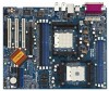
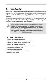
... BIOS setup and information of the motherboard and step-bystep guide to quality and endurance. In this manual will be subject to change without further notice. ASRock website http://www.asrock.com 1.1 Package Contents 1 x ASRock K8 Combo-Z Motherboard (ATX Form Factor: 12.0-in x 9.6-in, 30.5 cm x 24.4 cm) 1 x ASRock K8 Combo-Z Quick Installation Guide 1 x ASRock K8 Combo-Z Support CD 1 x Ultra ATA 66/100/133 IDE Ribbon Cable (80-conductor) 1 x 3.5-in Floppy Drive Ribbon Cable 1 x Serial ATA (SATA) Data Cable 1 x Serial ATA (SATA) HDD Power Cable (Optional) 1 x ASRock...
... BIOS setup and information of the motherboard and step-bystep guide to quality and endurance. In this manual will be subject to change without further notice. ASRock website http://www.asrock.com 1.1 Package Contents 1 x ASRock K8 Combo-Z Motherboard (ATX Form Factor: 12.0-in x 9.6-in, 30.5 cm x 24.4 cm) 1 x ASRock K8 Combo-Z Quick Installation Guide 1 x ASRock K8 Combo-Z Support CD 1 x Ultra ATA 66/100/133 IDE Ribbon Cable (80-conductor) 1 x 3.5-in Floppy Drive Ribbon Cable 1 x Serial ATA (SATA) Data Cable 1 x Serial ATA (SATA) HDD Power Cable (Optional) 1 x ASRock...
User Manual
Page 6
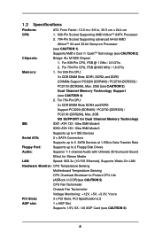
... for Dual Channel Memory Technology IDE: IDE1: ATA 133 / Ultra DMA Mode 6 IDE2: ATA 133 / Ultra DMA Mode 6 Supports up to 4 IDE Devices Serial ATA: 2 x SATA Connectors Supports up to 2 SATA Devices at 1.5Gb/s Data Transfer Rate Floppy Port: Supports up to 2 Floppy Disk Drives Audio: Superior 7.1-channel Audio with Ultimate 3D Surround Sound Effect for Stereo Media LAN: Speed: 802.3u (10/100 Ethernet), Supports Wake-On-LAN Hardware Monitor: CPU Temperature Sensing Motherboard Temperature Sensing CPU Overheat Shutdown to Protect CPU Life (ASRock U-COP)(see CAUTION 5) CPU Fan...
... for Dual Channel Memory Technology IDE: IDE1: ATA 133 / Ultra DMA Mode 6 IDE2: ATA 133 / Ultra DMA Mode 6 Supports up to 4 IDE Devices Serial ATA: 2 x SATA Connectors Supports up to 2 SATA Devices at 1.5Gb/s Data Transfer Rate Floppy Port: Supports up to 2 Floppy Disk Drives Audio: Superior 7.1-channel Audio with Ultimate 3D Surround Sound Effect for Stereo Media LAN: Speed: 802.3u (10/100 Ethernet), Supports Wake-On-LAN Hardware Monitor: CPU Temperature Sensing Motherboard Temperature Sensing CPU Overheat Shutdown to Protect CPU Life (ASRock U-COP)(see CAUTION 5) CPU Fan...
User Manual
Page 8
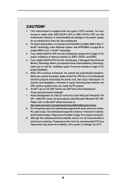
...page 14 for proper connection. 9. Before you install a 939-Pin CPU into this motherboard, it is detected, the system will support Dual Channel Memory Technology. To improve heat dissipation, remember to perform over-clocking. For microphone input, this motherboard! It may cause permanent damage! 7. Power Management for proper installation of this motherboard supports both of CPU sockets. Although this motherboard supports 2-channel, 4-channel, 6-channel, and 8-channel modes. Frequencies other than the recommended CPU bus frequencies may choose to enable AMD's Cool...
...page 14 for proper connection. 9. Before you install a 939-Pin CPU into this motherboard, it is detected, the system will support Dual Channel Memory Technology. To improve heat dissipation, remember to perform over-clocking. For microphone input, this motherboard! It may cause permanent damage! 7. Power Management for proper installation of this motherboard supports both of CPU sockets. Although this motherboard supports 2-channel, 4-channel, 6-channel, and 8-channel modes. Frequencies other than the recommended CPU bus frequencies may choose to enable AMD's Cool...
User Manual
Page 12
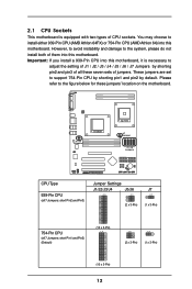
... (2 x 3-Pin) (1 x 3-Pin) 754-Pin CPU (all these jumpers' location on the motherboard. Important: If you install a 939-Pin CPU into this motherboard, it is equipped with two types of jumpers. 2.1 CPU Sockets This motherboard is necessary to adjust the setting of J1 / J2 / J3 / J4 / J5 / J6 / J7 Jumpers by default. However, to avoid instability and damage to support 754-Pin CPU by shorting pin1 and pin2 by shorting pin2 and pin3 of all 7 Jumpers: short...
... (2 x 3-Pin) (1 x 3-Pin) 754-Pin CPU (all these jumpers' location on the motherboard. Important: If you install a 939-Pin CPU into this motherboard, it is equipped with two types of jumpers. 2.1 CPU Sockets This motherboard is necessary to adjust the setting of J1 / J2 / J3 / J4 / J5 / J6 / J7 Jumpers by default. However, to avoid instability and damage to support 754-Pin CPU by shorting pin1 and pin2 by shorting pin2 and pin3 of all 7 Jumpers: short...
User Manual
Page 18
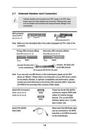
.../133 cable Note: If you use only one IDE device on the motherboard. 18 2.7 Onboard Headers and Connectors Onboard headers and connectors are NOT jumpers. Serial ATA (SATA) Data Cable Either end of your hard disk drive to the primary IDE connector (IDE1, blue) and CD-ROM to the SATA hard disk or the SATA connector on this motherboard, please set the IDE device as "Master". FDD connector (33-pin FLOPPY1) (see p.9, No. 13) PIN1 IDE1 PIN1 IDE2 connect the blue end connect the...
.../133 cable Note: If you use only one IDE device on the motherboard. 18 2.7 Onboard Headers and Connectors Onboard headers and connectors are NOT jumpers. Serial ATA (SATA) Data Cable Either end of your hard disk drive to the primary IDE connector (IDE1, blue) and CD-ROM to the SATA hard disk or the SATA connector on this motherboard, please set the IDE device as "Master". FDD connector (33-pin FLOPPY1) (see p.9, No. 13) PIN1 IDE1 PIN1 IDE2 connect the blue end connect the...
User Manual
Page 19
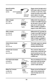
...-use USB 2.0 ports on the rear panel. Please connect the Bridge fan cable to this USB 2.0 header is an interface for the front panel audio cable that allows convenient connection and control of audio devices. Front Panel Audio Header (9-pin AUDIO1) (see p.9, No. 28) Bridge Fan Connector (3-pin NB_FAN1) (see p.9, No. 26) IRTX +5V DUMMY 1 GND IRRX CD-R GND GND CD-L This header supports an optional wireless transmitting and receiving infrared module. L GND A U D - Serial ATA (SATA) Power Cable (Optional) connect to the SATA HDD power connector connect...
...-use USB 2.0 ports on the rear panel. Please connect the Bridge fan cable to this USB 2.0 header is an interface for the front panel audio cable that allows convenient connection and control of audio devices. Front Panel Audio Header (9-pin AUDIO1) (see p.9, No. 28) Bridge Fan Connector (3-pin NB_FAN1) (see p.9, No. 26) IRTX +5V DUMMY 1 GND IRRX CD-R GND GND CD-L This header supports an optional wireless transmitting and receiving infrared module. L GND A U D - Serial ATA (SATA) Power Cable (Optional) connect to the SATA HDD power connector connect...
User Manual
Page 20
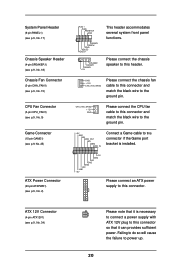
Please connect an ATX power supply to the ground pin. System Panel Header (9-pin PANEL1) (see p.9, No. 17) Chassis Speaker Header (4-pin SPEAKER 1) (see p.9, No. 34) Please note that it is necessary to connect a power supply with ATX 12V plug to this header. CPU Fan Connector (3-pin CPU_FAN1) (see p.9, No. 9) CPU_FAN_SPEED +12V GND Please connect the CPU fan cable to this connector and match the black wire to this connector. Failing to do so will cause the failure to the ground pin. Chassis Fan Connector (3-pin CHA_FAN1...
Please connect an ATX power supply to the ground pin. System Panel Header (9-pin PANEL1) (see p.9, No. 17) Chassis Speaker Header (4-pin SPEAKER 1) (see p.9, No. 34) Please note that it is necessary to connect a power supply with ATX 12V plug to this header. CPU Fan Connector (3-pin CPU_FAN1) (see p.9, No. 9) CPU_FAN_SPEED +12V GND Please connect the CPU fan cable to this connector and match the black wire to this connector. Failing to do so will cause the failure to the ground pin. Chassis Fan Connector (3-pin CHA_FAN1...
User Manual
Page 25
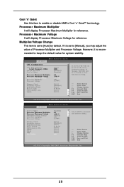
...] [Auto] [Auto] If AUTO, FID/VID will be left at the rated frequency/voltage. BIOS SETUP UTILITY Advanced Cool' n' Quiet Processor Maximum Multiplier Processor Maximum Voltage Multiplier/Voltage Change Processor Multiplier Processor Voltage Memory Clock Flexibility Option Bank Interleaving Burst Length CAS Latency (CL) TRCD TRAS TRP MA Timing [Enabled] x11 1.550 V [Manual] [x8] [1.500V] [Auto] [Disabled] [Auto] [8 Beats] [Auto] [Auto] [Auto] [Auto] [2T] Select DRAM commands and address timing. +F1 F9 F10 ESC Select Screen Select Item Change Option General Help Load Defaults...
...] [Auto] [Auto] If AUTO, FID/VID will be left at the rated frequency/voltage. BIOS SETUP UTILITY Advanced Cool' n' Quiet Processor Maximum Multiplier Processor Maximum Voltage Multiplier/Voltage Change Processor Multiplier Processor Voltage Memory Clock Flexibility Option Bank Interleaving Burst Length CAS Latency (CL) TRCD TRAS TRP MA Timing [Enabled] x11 1.550 V [Manual] [x8] [1.500V] [Auto] [Disabled] [Auto] [8 Beats] [Auto] [Auto] [Auto] [Auto] [2T] Select DRAM commands and address timing. +F1 F9 F10 ESC Select Screen Select Item Change Option General Help Load Defaults...
User Manual
Page 27
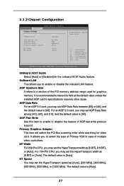
... Width For 939-Pin CPU, you to a section of multiple video controllers. The default value is [Auto]. OnBoard AC97 Audio Select [Auto] or [Disabled] for video card. AGP Aperture Size It refers to select the type of Primary VGA in case of the PCI memory address range used for graphics memory. It allows you may set the HyperTransport speed as [8 BIT], [16 BIT], or [Auto]. It is [4X]. Primary Graphics Adapter This item will switch the PCI Bus scanning order...
... Width For 939-Pin CPU, you to a section of multiple video controllers. The default value is [Auto]. OnBoard AC97 Audio Select [Auto] or [Disabled] for video card. AGP Aperture Size It refers to select the type of Primary VGA in case of the PCI memory address range used for graphics memory. It allows you may set the HyperTransport speed as [8 BIT], [16 BIT], or [Auto]. It is [4X]. Primary Graphics Adapter This item will switch the PCI Bus scanning order...
User Manual
Page 28
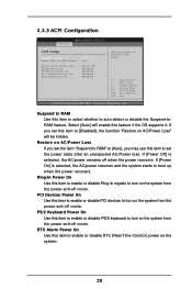
... RAM" to [Auto], you set this item to enable or disable PCI devices to power on the system from the power-soft-off mode. 3.3.3 ACPI Configuration Advanced BIOS SETUP UTILITY ACPI Settings Suspend To RAM Repost Video on STR Resume Restore on the system from the power-soft-off mode. If [Power On] is selected, the AC/power remains off mode. PCI Devices Power On Use this item to set the power state after an unexpected AC/Power loss. PS/2 Keyboard Power On Use...
... RAM" to [Auto], you set this item to enable or disable PCI devices to power on the system from the power-soft-off mode. 3.3.3 ACPI Configuration Advanced BIOS SETUP UTILITY ACPI Settings Suspend To RAM Repost Video on STR Resume Restore on the system from the power-soft-off mode. If [Power On] is selected, the AC/power remains off mode. PCI Devices Power On Use this item to set the power state after an unexpected AC/Power loss. PS/2 Keyboard Power On Use...
User Manual
Page 29
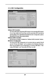
... . IDE Device Configuration You may set the IDE configuration for the device that you may enable either the primary IDE channel or the secondary IDE channel. We will disable the both IDE Controllers. +F1 F9 F10 ESC Select Screen Select Item Change Option General Help Load Defaults Save and Exit Exit v02.54 (C) Copyright 1985-2003, American Megatrends, Inc. 3.3.4 IDE Configuration BIOS SETUP UTILITY Advanced IDE Configuration OnBoard IDE Controller OnBoard SATA Controller Primary IDE Master Primary IDE Slave Secondary IDE Master Secondary IDE Slave [Both] [Enabled] [Hard Disk...
... . IDE Device Configuration You may set the IDE configuration for the device that you may enable either the primary IDE channel or the secondary IDE channel. We will disable the both IDE Controllers. +F1 F9 F10 ESC Select Screen Select Item Change Option General Help Load Defaults Save and Exit Exit v02.54 (C) Copyright 1985-2003, American Megatrends, Inc. 3.3.4 IDE Configuration BIOS SETUP UTILITY Advanced IDE Configuration OnBoard IDE Controller OnBoard SATA Controller Primary IDE Master Primary IDE Slave Secondary IDE Master Secondary IDE Slave [Both] [Enabled] [Hard Disk...
User Manual
Page 30
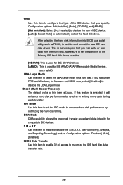
... the hard disk information into BIOS, use of IDE device. [Auto]: Select [Auto] to disable the use a disk utility, such as MO. for IDE ARMD (ATAPI Removable Media Device), such as FDISK, to partition and format the new IDE hard disk drives. Configuration options: [Disabled], [Auto], [Enabled]. 32-Bit Data Transfer Use this item to maximize the IDE hard disk data transfer rate. 30 S.M.A.R.T. LBA/Large Mode Use this item to enable 32-bit access to select the LBA/Large mode for compatible IDE devices. Configuration options: [Not Installed], [Auto], [CD/DVD], and...
... the hard disk information into BIOS, use of IDE device. [Auto]: Select [Auto] to disable the use a disk utility, such as MO. for IDE ARMD (ATAPI Removable Media Device), such as FDISK, to partition and format the new IDE hard disk drives. Configuration options: [Disabled], [Auto], [Enabled]. 32-Bit Data Transfer Use this item to maximize the IDE hard disk data transfer rate. 30 S.M.A.R.T. LBA/Large Mode Use this item to enable 32-bit access to select the LBA/Large mode for compatible IDE devices. Configuration options: [Not Installed], [Auto], [CD/DVD], and...
User Manual
Page 31
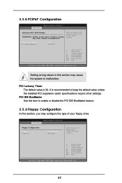
PCI Latency Timer PCI IDE BusMaster [64] [Enabled] +F1 F9 F10 ESC Select Screen Select Item Change Option General Help Load Defaults Save and Exit Exit v02.54 (C) Copyright 1985-2003, American Megatrends, Inc. BIOS SETUP UTILITY Advanced Floppy Configuration Floppy A Floppy B [1.44 MB 312"] [Disabled] Select the type of floppy drive connected to keep the default value unless the installed PCI expansion cards' specifications require other settings. PCI Latency Timer The default value is recommended to the system. +F1...
PCI Latency Timer PCI IDE BusMaster [64] [Enabled] +F1 F9 F10 ESC Select Screen Select Item Change Option General Help Load Defaults Save and Exit Exit v02.54 (C) Copyright 1985-2003, American Megatrends, Inc. BIOS SETUP UTILITY Advanced Floppy Configuration Floppy A Floppy B [1.44 MB 312"] [Disabled] Select the type of floppy drive connected to keep the default value unless the installed PCI expansion cards' specifications require other settings. PCI Latency Timer The default value is recommended to the system. +F1...
User Manual
Page 32
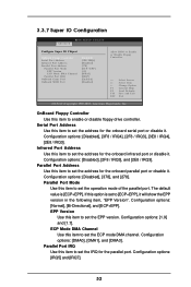
... to [ECP+EPP], it . Configuration options: [DMA0], [DMA1], and [DMA3]. Configuration options: [IRQ5] and [IRQ7]. 32 OnBoard Floppy Controller Use this item to set to set the address for the onboard serial port or disable it will show the EPP version in the following item, "EPP Version". Serial Port Address Use this item to Enable or Disable Floppy Controller. +F1 F9 F10 ESC Select Screen Select Item Change Option General Help Load Defaults Save and Exit Exit v02...
... to [ECP+EPP], it . Configuration options: [DMA0], [DMA1], and [DMA3]. Configuration options: [IRQ5] and [IRQ7]. 32 OnBoard Floppy Controller Use this item to set to set the address for the onboard serial port or disable it will show the EPP version in the following item, "EPP Version". Serial Port Address Use this item to Enable or Disable Floppy Controller. +F1 F9 F10 ESC Select Screen Select Item Change Option General Help Load Defaults Save and Exit Exit v02...
User Manual
Page 33
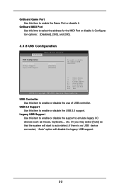
... USB Configuration BIOS SETUP UTILITY Advanced USB Configuration USB Controller USB 2.0 Support Legacy USB Support [Enabled] [Enabled] [Disabled] To enable or disable the onboard USB controllers. +F1 F9 F10 ESC Select Screen Select Item Change Option General Help Load Defaults Save and Exit Exit v02.54 (C) Copyright 1985-2003, American Megatrends, Inc. Legacy USB Support Use this item to enable the Game Port or disable it . USB 2.0 Support Use this item to auto-detect; if there is no USB device connected, "Auto" option will start to enable or disable the use of USB controller...
... USB Configuration BIOS SETUP UTILITY Advanced USB Configuration USB Controller USB 2.0 Support Legacy USB Support [Enabled] [Enabled] [Disabled] To enable or disable the onboard USB controllers. +F1 F9 F10 ESC Select Screen Select Item Change Option General Help Load Defaults Save and Exit Exit v02.54 (C) Copyright 1985-2003, American Megatrends, Inc. Legacy USB Support Use this item to enable the Game Port or disable it . USB 2.0 Support Use this item to auto-detect; if there is no USB device connected, "Auto" option will start to enable or disable the use of USB controller...
User Manual
Page 35
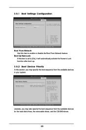
3.5.1 Boot Settings Configuration BIOS SETUP UTILITY Boot Boot Settings Configuration Boot From Network Bootup Num-Lock [Disabled] [On] To enable or disable the boot from the available devices. BIOS SETUP UTILITY Boot Boot Device Priority 1st Boot Device 2nd Boot Device 3rd Boot Device [1st FLOPPY DRIVE] [HDD: PM-MAXTOR 6L08] [CD / DVD: SM-CD-ROM C] Specifies the boot sequence from network feature. +F1 F9 F10 ESC Select Screen Select Item Change Option General Help Load Defaults Save and Exit Exit v02.54 (C) Copyright 1985-2003, American Megatrends, Inc. Likewise, you ...
3.5.1 Boot Settings Configuration BIOS SETUP UTILITY Boot Boot Settings Configuration Boot From Network Bootup Num-Lock [Disabled] [On] To enable or disable the boot from the available devices. BIOS SETUP UTILITY Boot Boot Device Priority 1st Boot Device 2nd Boot Device 3rd Boot Device [1st FLOPPY DRIVE] [HDD: PM-MAXTOR 6L08] [CD / DVD: SM-CD-ROM C] Specifies the boot sequence from network feature. +F1 F9 F10 ESC Select Screen Select Item Change Option General Help Load Defaults Save and Exit Exit v02.54 (C) Copyright 1985-2003, American Megatrends, Inc. Likewise, you ...
User Manual
Page 36
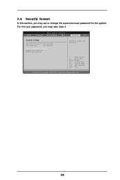
Main Advanced BIOS SETUP UTILITY H/W Monitor Boot Security Exit Security Settings Supervisor Password : Not Installed User Password : Not Installed Change Supervisor Password Change User Password Clear User Password Install or Change the password. For the user password, you may also clear it. Select Screen Select Item Enter Change F1 General Help F9 Load Defaults F10 Save and Exit ESC Exit v02.54 (C) Copyright 1985-2003, American Megatrends, Inc. 36 3.6 Security Screen In this section, you may set or change the supervisor/user password for the system.
Main Advanced BIOS SETUP UTILITY H/W Monitor Boot Security Exit Security Settings Supervisor Password : Not Installed User Password : Not Installed Change Supervisor Password Change User Password Clear User Password Install or Change the password. For the user password, you may also clear it. Select Screen Select Item Enter Change F1 General Help F9 Load Defaults F10 Save and Exit ESC Exit v02.54 (C) Copyright 1985-2003, American Megatrends, Inc. 36 3.6 Security Screen In this section, you may set or change the supervisor/user password for the system.
User Manual
Page 38
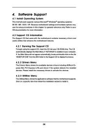
... computer. If the Main Menu did not appear automatically, locate and double click on a specific item then follow the installation wizard to display the menus. 4.2.2 Drivers Menu The Drivers Menu shows the available devices drivers including ASRock Express GbL PCI Express LAN card driver if the system detects the installed devices. Because motherboard settings and hardware options vary, use the setup procedures in the Support CD to install it. 38 Software Support 4.1 Install Operating System This motherboard supports various Microsoft® Windows® operating...
... computer. If the Main Menu did not appear automatically, locate and double click on a specific item then follow the installation wizard to display the menus. 4.2.2 Drivers Menu The Drivers Menu shows the available devices drivers including ASRock Express GbL PCI Express LAN card driver if the system detects the installed devices. Because motherboard settings and hardware options vary, use the setup procedures in the Support CD to install it. 38 Software Support 4.1 Install Operating System This motherboard supports various Microsoft® Windows® operating...

User Manual
Page 39
... system, click the Start button. From the Energy saving features of monitor group, click the "Settings..." Automatic mode is strongly recommended to install "AMD Processor Driver" from the "Support CD" first. Select Settings, then Control Panel. 2. Switch to implement settings. Double-click the Display icon in the Control Panel then select the Screen Saver tab. 3. Click OK to Classic View. (for Windows XP only) 3. From the Power schemes combo list box, select Minimal...
... system, click the Start button. From the Energy saving features of monitor group, click the "Settings..." Automatic mode is strongly recommended to install "AMD Processor Driver" from the "Support CD" first. Select Settings, then Control Panel. 2. Switch to implement settings. Double-click the Display icon in the Control Panel then select the Screen Saver tab. 3. Click OK to Classic View. (for Windows XP only) 3. From the Power schemes combo list box, select Minimal...


