
User Manual
Page 3
...Software Support 24 4.1 Install Operating System 24 4.2 Support CD Information 24 4.2.1 Running Support CD 24 4.2.2 Drivers Menu 24 4.2.3 Utilities Menu 24 4.2.4 ASRock "PC-DIY Live Demo" Program 24 4.2.5 Contact Information 24 Appendix 25 1. Exit Menu 33 3 BIOS Setup 20 3.1 BIOS Setup Utility 20 ... Swap Functions for SATA HDDs 18 2.9 Making An SATA Driver Diskette 19 3. Security Setup Menu 30 3. Introduction 4 1.1 Package Contents 4 1.2 Specifications 5 1.3 Motherboard Layout 7 1.4 ASRock I/O Plus 8 TM ...2. Boot Setup Menu 32 5. Advanced BIOS Setup Menu 25 2.
...Software Support 24 4.1 Install Operating System 24 4.2 Support CD Information 24 4.2.1 Running Support CD 24 4.2.2 Drivers Menu 24 4.2.3 Utilities Menu 24 4.2.4 ASRock "PC-DIY Live Demo" Program 24 4.2.5 Contact Information 24 Appendix 25 1. Exit Menu 33 3 BIOS Setup 20 3.1 BIOS Setup Utility 20 ... Swap Functions for SATA HDDs 18 2.9 Making An SATA Driver Diskette 19 3. Security Setup Menu 30 3. Introduction 4 1.1 Package Contents 4 1.2 Specifications 5 1.3 Motherboard Layout 7 1.4 ASRock I/O Plus 8 TM ...2. Boot Setup Menu 32 5. Advanced BIOS Setup Menu 25 2.

User Manual
Page 4
... setup and support CD information. ASRock website http://www.asrock.com 1.1 Package Contents 1 x ASRock K7VT6 Motherboard (ATX Form Factor: 12.0-in x 7.0-in, 30.5 cm x 17.8 cm) 1 x ASRock K7VT6 Quick Installation Guide 1 x ASRock K7VT6 Support CD 1 x Ultra ATA 66/100/133 IDE Ribbon Cable (80-conductor) 1 x 3.5-in Appendix on page 25 for purchasing ASRock K7VT6 motherboard, a reliable motherboard produced under ASRock's consistently stringent quality control...
... setup and support CD information. ASRock website http://www.asrock.com 1.1 Package Contents 1 x ASRock K7VT6 Motherboard (ATX Form Factor: 12.0-in x 7.0-in, 30.5 cm x 17.8 cm) 1 x ASRock K7VT6 Quick Installation Guide 1 x ASRock K7VT6 Support CD 1 x Ultra ATA 66/100/133 IDE Ribbon Cable (80-conductor) 1 x 3.5-in Appendix on page 25 for purchasing ASRock K7VT6 motherboard, a reliable motherboard produced under ASRock's consistently stringent quality control...

User Manual
Page 5
... Audio LAN: Speed: 802.3u (10/100 Ethernet), Supports Wake-On-LAN Hardware Monitor: CPU Temperature Sensing Motherboard Temperature Sensing CPU Overheat Shutdown to Protect CPU Life (ASRock U-COP)(see CAUTION 1) CPU Fan Tachometer Chassis Fan Tachometer Voltage Monitoring: +12V, +5V, +3.3V, Vcore... USB 2.0 ports: include 6 ready-to-use USB 2.0 ports on the rear panel, plus one on-board header supporting 2 extra USB 2.0 ports (see CAUTION 3) ASRock I/O PlusTM: 1 PS/2 Mouse Port, 1 PS/2 Keyboard Port, 1 Serial Port: COM1, 1 Parallel Port (ECP/EPP Support) 6 ready-to-use USB 2.0 ...
... Audio LAN: Speed: 802.3u (10/100 Ethernet), Supports Wake-On-LAN Hardware Monitor: CPU Temperature Sensing Motherboard Temperature Sensing CPU Overheat Shutdown to Protect CPU Life (ASRock U-COP)(see CAUTION 1) CPU Fan Tachometer Chassis Fan Tachometer Voltage Monitoring: +12V, +5V, +3.3V, Vcore... USB 2.0 ports: include 6 ready-to-use USB 2.0 ports on the rear panel, plus one on-board header supporting 2 extra USB 2.0 ports (see CAUTION 3) ASRock I/O PlusTM: 1 PS/2 Mouse Port, 1 PS/2 Keyboard Port, 1 Serial Port: COM1, 1 Parallel Port (ECP/EPP Support) 6 ready-to-use USB 2.0 ...

User Manual
Page 6
... BIOS. Frequencies other than the recommended CPU bus frequencies may cause permanent damage! 3. Do NOT use a 3.3V AGP card on the motherboard functions properly and unplug the power cord, then plug it is detected, the system will automatically shutdown. Please refer to the FSB of this...properly under Microsoft® Windows® XP SP1/2000 SP4. The CPU host frequency of the system or damage the CPU. Although this motherboard offers stepless control, it back again. You must adjust "FSB Select Jumpers" according to Microsoft® official document at http://www.microsoft....
... BIOS. Frequencies other than the recommended CPU bus frequencies may cause permanent damage! 3. Do NOT use a 3.3V AGP card on the motherboard functions properly and unplug the power cord, then plug it is detected, the system will automatically shutdown. Please refer to the FSB of this...properly under Microsoft® Windows® XP SP1/2000 SP4. The CPU host frequency of the system or damage the CPU. Although this motherboard offers stepless control, it back again. You must adjust "FSB Select Jumpers" according to Microsoft® official document at http://www.microsoft....

User Manual
Page 7
1.3 Motherboard Layout 1 2 34 5 6 17.8cm (7.0 in) PS/2 MOUSE PS/2 KEYBOARD PS2_USB_PWR1 1 FID4 FID3 FID2 FID1 FID0 J1 CPU_FAN1 1 1 1 1 1 SOCKET 462 SERIAL PORT (COM1) PARALLEL PORT DDR 1 (... Top: RJ-45 B: USB1 USB 2.0 T: USB4 1 B: USB5 JUSB45 VIA KT600 CHIPSET Top: Line In Center: Line Out Bottom: Mic In 27 2MB BIOS AGP 8X K7VT6 LAN PHY SUPER I/O 1.5V_AGP1 IDE1 IDE2 7 8 9 26 25 24 23 22 GAME1 1 DDR400 PCI1 PCI2 1 FSB_SEL0 1 FSB_SEL1 1 FSB_SEL2 1 AUDIO1 JR1 JL1 CMOS BATTERY USB2.0 1 CLRCMOS2...
1.3 Motherboard Layout 1 2 34 5 6 17.8cm (7.0 in) PS/2 MOUSE PS/2 KEYBOARD PS2_USB_PWR1 1 FID4 FID3 FID2 FID1 FID0 J1 CPU_FAN1 1 1 1 1 1 SOCKET 462 SERIAL PORT (COM1) PARALLEL PORT DDR 1 (... Top: RJ-45 B: USB1 USB 2.0 T: USB4 1 B: USB5 JUSB45 VIA KT600 CHIPSET Top: Line In Center: Line Out Bottom: Mic In 27 2MB BIOS AGP 8X K7VT6 LAN PHY SUPER I/O 1.5V_AGP1 IDE1 IDE2 7 8 9 26 25 24 23 22 GAME1 1 DDR400 PCI1 PCI2 1 FSB_SEL0 1 FSB_SEL1 1 FSB_SEL2 1 AUDIO1 JR1 JL1 CMOS BATTERY USB2.0 1 CLRCMOS2...
User Manual
Page 9
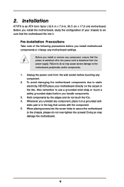
...remember to the chassis, please do not over-tighten the screws! Whenever you handle components. 3. 2. Pre-installation Precautions Take note of your motherboard directly on a grounded antistatic pad or in the bag that the power is switched off or the power cord is an ATX form factor (...the carpet or the like. Before you install motherboard components or change any component. 2. Doing so may cause severe damage to do not touch the ICs. 4. Hold components by the edges and do so may damage the motherboard. 9 Installation K7VT6 is detached from the wall socket before you...
...remember to the chassis, please do not over-tighten the screws! Whenever you handle components. 3. 2. Pre-installation Precautions Take note of your motherboard directly on a grounded antistatic pad or in the bag that the power is switched off or the power cord is an ATX form factor (...the carpet or the like. Before you install motherboard components or change any component. 2. Doing so may cause severe damage to do not touch the ICs. 4. Hold components by the edges and do so may damage the motherboard. 9 Installation K7VT6 is detached from the wall socket before you...

User Manual
Page 11
Please make sure to the motherboard and the DIMM if you force the DIMM into the slot until the retaining clips at incorrect orientation. Step 2. It will cause permanent damage to ... retaining clips outward. Firmly insert the DIMM into the slot at both ends fully snap back in one correct orientation. 2.3 Installation of Memory Modules (DIMM) K7VT6 motherboard provides two 184-pin DDR (Double Data Rate) DIMM slots. notch break notch break The DIMM only fits in place and the DIMM is properly...
Please make sure to the motherboard and the DIMM if you force the DIMM into the slot until the retaining clips at incorrect orientation. Step 2. It will cause permanent damage to ... retaining clips outward. Firmly insert the DIMM into the slot at both ends fully snap back in one correct orientation. 2.3 Installation of Memory Modules (DIMM) K7VT6 motherboard provides two 184-pin DDR (Double Data Rate) DIMM slots. notch break notch break The DIMM only fits in place and the DIMM is properly...

User Manual
Page 12
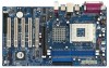
...Align the card connector with screws. Replace the system cover. 12 Step 2. Step 3. Step 4. Fasten the card to use a 3.3V AGP card on K7VT6 motherboard. AGP slot: The AGP slot is completely seated on the slot. Please do NOT use . PCI slots: PCI slots are 5 PCI slots and 1 AGP... slot on the AGP slot of your motherboard is unplugged. For the voltage information of this motherboard! The ASRock AGP slot has a special design of the expansion card and make sure that you start the installation. 2.4 Expansion Slots...
...Align the card connector with screws. Replace the system cover. 12 Step 2. Step 3. Step 4. Fasten the card to use a 3.3V AGP card on K7VT6 motherboard. AGP slot: The AGP slot is completely seated on the slot. Please do NOT use . PCI slots: PCI slots are 5 PCI slots and 1 AGP... slot on the AGP slot of your motherboard is unplugged. For the voltage information of this motherboard! The ASRock AGP slot has a special design of the expansion card and make sure that you start the installation. 2.4 Expansion Slots...

User Manual
Page 13
... turn off the computer and unplug the power cord from the power supply. To clear and reset the system parameters to the FSB of this motherboard is "Open". 2.5 Jumpers Setup The illustration shows how jumpers are "Short" when jumper cap is "Short". If no jumper cap is placed on these 2 pins...
... turn off the computer and unplug the power cord from the power supply. To clear and reset the system parameters to the FSB of this motherboard is "Open". 2.5 Jumpers Setup The illustration shows how jumpers are "Short" when jumper cap is "Short". If no jumper cap is placed on these 2 pins...

User Manual
Page 15
..., blue) and CD-ROM to the IDE devices 80-conductor, ATA 66/100/133 cable Note: If you use only one IDE device on the motherboard. 15 The current SATA interface allows up to optimize compatibility and performance, please connect your IDE device vendor for internal storage devices. Primary IDE Connector..., see p.7 item 8) Secondary IDE Connector (Black) (39-pin IDE2, see p.7 item 7) PIN1 IDE1 PIN1 IDE2 connect the blue end connect the black end to the motherboard to the secondary IDE connector (IDE2, black). Please refer to the SATA hard disk or the SATA connector on this...
..., blue) and CD-ROM to the IDE devices 80-conductor, ATA 66/100/133 cable Note: If you use only one IDE device on the motherboard. 15 The current SATA interface allows up to optimize compatibility and performance, please connect your IDE device vendor for internal storage devices. Primary IDE Connector..., see p.7 item 8) Secondary IDE Connector (Black) (39-pin IDE2, see p.7 item 7) PIN1 IDE1 PIN1 IDE2 connect the blue end connect the black end to the motherboard to the secondary IDE connector (IDE2, black). Please refer to the SATA hard disk or the SATA connector on this...

User Manual
Page 18
... disks. What is Hot Swap Function? If the SATA HDDs are built as RAID1 then it is called "Hot Plug" for the action to the motherboard's SATA connector. STEP 1: Install the SATA hard disks into the SATA HDD. However, please note that supports Serial ATA (SATA) hard disks and RAID ... for RAID configuration, it is called "Hot Swap" for the action to the SATA hard disk. 2.8 Hot Plug and Hot Swap Functions for SATA HDDs K7VT6 motherboard supports Hot Plug and Hot Swap functions for internal storage devices. STEP 3: Connect one end of the SATA data cable to insert and remove the...
... disks. What is Hot Swap Function? If the SATA HDDs are built as RAID1 then it is called "Hot Plug" for the action to the motherboard's SATA connector. STEP 1: Install the SATA hard disks into the SATA HDD. However, please note that supports Serial ATA (SATA) hard disks and RAID ... for RAID configuration, it is called "Hot Swap" for the action to the SATA hard disk. 2.8 Hot Plug and Hot Swap Functions for SATA HDDs K7VT6 motherboard supports Hot Plug and Hot Swap functions for internal storage devices. STEP 3: Connect one end of the SATA data cable to insert and remove the...
User Manual
Page 20
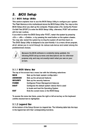
... scroll through its test routines. Because the BIOS software is a legend bar. 3. You may also restart the system by pressing the reset button on the motherboard stores the BIOS Setup Utility. The following BIOS setup screens and descriptions are for reference purpose only, and may not exactly match what you start...
... scroll through its test routines. Because the BIOS software is a legend bar. 3. You may also restart the system by pressing the reset button on the motherboard stores the BIOS Setup Utility. The following BIOS setup screens and descriptions are for reference purpose only, and may not exactly match what you start...

User Manual
Page 24
... Player® to play the file. 4.2.5 Contact Information If you need to contact ASRock or want to know more information. 4.2 Support CD Information The Support CD that came with the motherboard contains necessary drivers and useful utilities that the motherboard supports. If the Main Menu did not appear automatically, locate and double click...
... Player® to play the file. 4.2.5 Contact Information If you need to contact ASRock or want to know more information. 4.2 Support CD Information The Support CD that came with the motherboard contains necessary drivers and useful utilities that the motherboard supports. If the Main Menu did not appear automatically, locate and double click...

User Manual
Page 25
...Spectrum CPU Host Frequency Actual Frequency DRAM Frequency Flexibility Option Disabled Auto 133MHz Auto Disabled [ Setup Help ] to [Auto], the motherboard will detect the inserted memory module(s) and automatically assign appropriate frequency. However, because the CPU host frequency of spread spectrum. It...stability. This is [Disabled]. Advanced BIOS Setup Menu Main Advanced AMIBIOS SETUP UTILITY - Flexibility Option The default value of this motherboard is set to set to enable or disable the feature of this option is not recommended unless you the following BIOS Setup menus...
...Spectrum CPU Host Frequency Actual Frequency DRAM Frequency Flexibility Option Disabled Auto 133MHz Auto Disabled [ Setup Help ] to [Auto], the motherboard will detect the inserted memory module(s) and automatically assign appropriate frequency. However, because the CPU host frequency of spread spectrum. It...stability. This is [Disabled]. Advanced BIOS Setup Menu Main Advanced AMIBIOS SETUP UTILITY - Flexibility Option The default value of this motherboard is set to set to enable or disable the feature of this option is not recommended unless you the following BIOS Setup menus...

User Manual
Page 29
OnBoard AC'97 Audio Select [Disabled], [Auto] or [Enabled] for CPU temperature, Motherboard temperature, CPU fan speed, and critical voltage. VERSION 3.31a System Hardware Monitor [ Setup Help ] CPU Temperature M / B Temperature CPU FAN Speed Chassis FAN Speed Vcore + 3.30V + 5....
OnBoard AC'97 Audio Select [Disabled], [Auto] or [Enabled] for CPU temperature, Motherboard temperature, CPU fan speed, and critical voltage. VERSION 3.31a System Hardware Monitor [ Setup Help ] CPU Temperature M / B Temperature CPU FAN Speed Chassis FAN Speed Vcore + 3.30V + 5....

