
User Manual
Page 3
... Operating System 24 4.2 Support CD Information 24 4.2.1 Running Support CD 24 4.2.2 Drivers Menu 24 4.2.3 Utilities Menu 24 4.2.4 ASRock "PC-DIY Live Demo" Program 24 4.2.5 Contact Information 24 Appendix 25 1. Contents 1. Introduction 4 1.1 Package Contents 4 1.2 Specifications 5 1.3 Motherboard Layout 7 1.4 ASRock I/O Plus 8 TM ...2. Installation 9 Pre-installation Precautions 9 2.1 CPU Installation 10 2.2 Installation of CPU Fan and Heatsink 10...
... Operating System 24 4.2 Support CD Information 24 4.2.1 Running Support CD 24 4.2.2 Drivers Menu 24 4.2.3 Utilities Menu 24 4.2.4 ASRock "PC-DIY Live Demo" Program 24 4.2.5 Contact Information 24 Appendix 25 1. Contents 1. Introduction 4 1.1 Package Contents 4 1.2 Specifications 5 1.3 Motherboard Layout 7 1.4 ASRock I/O Plus 8 TM ...2. Installation 9 Pre-installation Precautions 9 2.1 CPU Installation 10 2.2 Installation of CPU Fan and Heatsink 10...

User Manual
Page 4
... of this manual contain introduction of advanced BIOS setup can be subject to quality and endurance. ASRock website http://www.asrock.com 1.1 Package Contents 1 x ASRock K7VT6 Motherboard (ATX Form Factor: 12.0-in x 7.0-in, 30.5 cm x 17.8 cm) 1 x ASRock K7VT6 Quick Installation Guide 1 x ASRock K7VT6 Support CD 1 x Ultra ATA 66/100/133 IDE Ribbon Cable (80-conductor) 1 x 3.5-in Appendix on...
... of this manual contain introduction of advanced BIOS setup can be subject to quality and endurance. ASRock website http://www.asrock.com 1.1 Package Contents 1 x ASRock K7VT6 Motherboard (ATX Form Factor: 12.0-in x 7.0-in, 30.5 cm x 17.8 cm) 1 x ASRock K7VT6 Quick Installation Guide 1 x ASRock K7VT6 Support CD 1 x Ultra ATA 66/100/133 IDE Ribbon Cable (80-conductor) 1 x 3.5-in Appendix on...

User Manual
Page 5
... Audio LAN: Speed: 802.3u (10/100 Ethernet), Supports Wake-On-LAN Hardware Monitor: CPU Temperature Sensing Motherboard Temperature Sensing CPU Overheat Shutdown to Protect CPU Life (ASRock U-COP)(see CAUTION 1) CPU Fan Tachometer Chassis Fan Tachometer Voltage Monitoring: +12V, +5V, +3.3V, Vcore... USB 2.0 ports: include 6 ready-to-use USB 2.0 ports on the rear panel, plus one on-board header supporting 2 extra USB 2.0 ports (see CAUTION 3) ASRock I/O PlusTM: 1 PS/2 Mouse Port, 1 PS/2 Keyboard Port, 1 Serial Port: COM1, 1 Parallel Port (ECP/EPP Support) 6 ready-to-use USB 2.0 ...
... Audio LAN: Speed: 802.3u (10/100 Ethernet), Supports Wake-On-LAN Hardware Monitor: CPU Temperature Sensing Motherboard Temperature Sensing CPU Overheat Shutdown to Protect CPU Life (ASRock U-COP)(see CAUTION 1) CPU Fan Tachometer Chassis Fan Tachometer Voltage Monitoring: +12V, +5V, +3.3V, Vcore... USB 2.0 ports: include 6 ready-to-use USB 2.0 ports on the rear panel, plus one on-board header supporting 2 extra USB 2.0 ports (see CAUTION 3) ASRock I/O PlusTM: 1 PS/2 Mouse Port, 1 PS/2 Keyboard Port, 1 Serial Port: COM1, 1 Parallel Port (ECP/EPP Support) 6 ready-to-use USB 2.0 ...

User Manual
Page 6
... 6 To improve heat dissipation, remember to the FSB of "User Manual" in BIOS. Do NOT use a 3.3V AGP card on the motherboard functions properly and unplug the power cord, then plug it is not recommended to Microsoft® official document at http://www.microsoft.com/whdc/hwdev.../bus/USB/USB2support.mspx 4. It may cause the instability of this motherboard offers stepless control, it back again. While CPU overheat is determined by jumper-setting. Although this motherboard! It may not work properly under Microsoft® Windows® XP SP1/2000 SP4...
... 6 To improve heat dissipation, remember to the FSB of "User Manual" in BIOS. Do NOT use a 3.3V AGP card on the motherboard functions properly and unplug the power cord, then plug it is not recommended to Microsoft® official document at http://www.microsoft.com/whdc/hwdev.../bus/USB/USB2support.mspx 4. It may cause the instability of this motherboard offers stepless control, it back again. While CPU overheat is determined by jumper-setting. Although this motherboard! It may not work properly under Microsoft® Windows® XP SP1/2000 SP4...

User Manual
Page 7
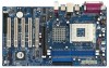
1.3 Motherboard Layout 1 2 34 5 6 17.8cm (7.0 in) PS/2 MOUSE PS/2 KEYBOARD PS2_USB_PWR1 1 FID4 FID3 FID2 FID1 FID0 J1 CPU_FAN1 1 1 1 1 1 SOCKET 462 SERIAL PORT (COM1) PARALLEL PORT DDR 1 (... Top: RJ-45 B: USB1 USB 2.0 T: USB4 1 B: USB5 JUSB45 VIA KT600 CHIPSET Top: Line In Center: Line Out Bottom: Mic In 27 2MB BIOS AGP 8X K7VT6 LAN PHY SUPER I/O 1.5V_AGP1 IDE1 IDE2 7 8 9 26 25 24 23 22 GAME1 1 DDR400 PCI1 PCI2 1 FSB_SEL0 1 FSB_SEL1 1 FSB_SEL2 1 AUDIO1 JR1 JL1 CMOS BATTERY USB2.0 1 CLRCMOS2...
1.3 Motherboard Layout 1 2 34 5 6 17.8cm (7.0 in) PS/2 MOUSE PS/2 KEYBOARD PS2_USB_PWR1 1 FID4 FID3 FID2 FID1 FID0 J1 CPU_FAN1 1 1 1 1 1 SOCKET 462 SERIAL PORT (COM1) PARALLEL PORT DDR 1 (... Top: RJ-45 B: USB1 USB 2.0 T: USB4 1 B: USB5 JUSB45 VIA KT600 CHIPSET Top: Line In Center: Line Out Bottom: Mic In 27 2MB BIOS AGP 8X K7VT6 LAN PHY SUPER I/O 1.5V_AGP1 IDE1 IDE2 7 8 9 26 25 24 23 22 GAME1 1 DDR400 PCI1 PCI2 1 FSB_SEL0 1 FSB_SEL1 1 FSB_SEL2 1 AUDIO1 JR1 JL1 CMOS BATTERY USB2.0 1 CLRCMOS2...
User Manual
Page 9
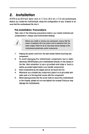
... over-tighten the screws! Pre-installation Precautions Take note of the following precautions before you install the motherboard, study the configuration of your motherboard directly on a grounded antistatic pad or in , 30.5 cm x 17.8 cm) motherboard. Installation K7VT6 is detached from the wall socket before touching any component, ensure that the power is switched...
... over-tighten the screws! Pre-installation Precautions Take note of the following precautions before you install the motherboard, study the configuration of your motherboard directly on a grounded antistatic pad or in , 30.5 cm x 17.8 cm) motherboard. Installation K7VT6 is detached from the wall socket before touching any component, ensure that the power is switched...

User Manual
Page 11
...or removing DIMMs or the system components. Step 2. Unlock a DIMM slot by pressing the retaining clips outward. 2.3 Installation of Memory Modules (DIMM) K7VT6 motherboard provides two 184-pin DDR (Double Data Rate) DIMM slots. Step 3. notch break notch break The DIMM only fits in place and the DIMM ...is properly seated. 11 Step 1. Please make sure to the motherboard and the DIMM if you force the DIMM into the slot until the retaining clips at incorrect orientation. Firmly insert the DIMM into the ...
...or removing DIMMs or the system components. Step 2. Unlock a DIMM slot by pressing the retaining clips outward. 2.3 Installation of Memory Modules (DIMM) K7VT6 motherboard provides two 184-pin DDR (Double Data Rate) DIMM slots. Step 3. notch break notch break The DIMM only fits in place and the DIMM ...is properly seated. 11 Step 1. Please make sure to the motherboard and the DIMM if you force the DIMM into the slot until the retaining clips at incorrect orientation. Firmly insert the DIMM into the ...

User Manual
Page 12
.... AGP slot: The AGP slot is completely seated on K7VT6 motherboard. It may cause permanent damage! For the voltage information of clasp that you start the installation. The ASRock AGP slot has a special design of your motherboard is unplugged. Please read the documentation of this motherboard! Fasten the card to install a graphics card. Please do...
.... AGP slot: The AGP slot is completely seated on K7VT6 motherboard. It may cause permanent damage! For the voltage information of clasp that you start the installation. The ASRock AGP slot has a special design of your motherboard is unplugged. Please read the documentation of this motherboard! Fasten the card to install a graphics card. Please do...

User Manual
Page 13
... OPEN 1_2 2_3 FSB_SEL2 FSB 400MHz Note: The CPU FSB frequency of your AMD CPU. Please follow the figures above to the FSB of this motherboard is "Short". When the jumper cap is placed on these 2 pins.
... OPEN 1_2 2_3 FSB_SEL2 FSB 400MHz Note: The CPU FSB frequency of your AMD CPU. Please follow the figures above to the FSB of this motherboard is "Short". When the jumper cap is placed on these 2 pins.

User Manual
Page 15
... rate. FDD Connector (33-pin FLOPPY1) (see p.7 item 7) PIN1 IDE1 PIN1 IDE2 connect the blue end connect the black end to the motherboard to Pin1 Note: Make sure the red-striped side of the cable is plugged into Pin1 side of your IDE device vendor for internal storage... devices. The current SATA interface allows up to the SATA hard disk or the SATA connector on this motherboard, please set the IDE device as "Master". Please refer to the secondary IDE connector (IDE2, black). Besides, to optimize compatibility and performance...
... rate. FDD Connector (33-pin FLOPPY1) (see p.7 item 7) PIN1 IDE1 PIN1 IDE2 connect the blue end connect the black end to the motherboard to Pin1 Note: Make sure the red-striped side of the cable is plugged into Pin1 side of your IDE device vendor for internal storage... devices. The current SATA interface allows up to the SATA hard disk or the SATA connector on this motherboard, please set the IDE device as "Master". Please refer to the secondary IDE connector (IDE2, black). Besides, to optimize compatibility and performance...

User Manual
Page 18
... STEP 1: Install the SATA hard disks into the SATA HDD. STEP 3: Connect one end of your chassis. What is still power-on this motherboard for internal storage devices. However, please note that supports Serial ATA (SATA) hard disks and RAID functions. If SATA HDDs are NOT set for...Plug" for the action to the SATA hard disk. 2.8 Hot Plug and Hot Swap Functions for SATA HDDs K7VT6 motherboard supports Hot Plug and Hot Swap functions for the action to the motherboard's SATA connector. You may install SATA hard disks on and in working condition. 18 STEP 4: Connect the ...
... STEP 1: Install the SATA hard disks into the SATA HDD. STEP 3: Connect one end of your chassis. What is still power-on this motherboard for internal storage devices. However, please note that supports Serial ATA (SATA) hard disks and RAID functions. If SATA HDDs are NOT set for...Plug" for the action to the SATA hard disk. 2.8 Hot Plug and Hot Swap Functions for SATA HDDs K7VT6 motherboard supports Hot Plug and Hot Swap functions for the action to the motherboard's SATA connector. You may install SATA hard disks on and in working condition. 18 STEP 4: Connect the ...
User Manual
Page 20
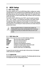
... what you to enter the BIOS Setup after POST, restart the system by pressing + + , or by turning the system off and then back on the motherboard stores the BIOS Setup Utility. 3. If you start up the security features POWER Configures Power Management features BOOT Configures the default system device that is...
... what you to enter the BIOS Setup after POST, restart the system by pressing + + , or by turning the system off and then back on the motherboard stores the BIOS Setup Utility. 3. If you start up the security features POWER Configures Power Management features BOOT Configures the default system device that is...

User Manual
Page 24
... know more information. 4.2 Support CD Information The Support CD that came with the motherboard contains necessary drivers and useful utilities that the motherboard supports. or you need to contact ASRock or want to play the file. 4.2.5 Contact Information If you may contact your ... the following path: ..\ MPEGAV \ AVSEQ01.DAT To see this chapter for more about ASRock, welcome to your OS documentation for general reference only. Software Support 4.1 Install Operating System This motherboard supports various Microsoft® Windows® operating systems: 98 SE / ME / 2000 ...
... know more information. 4.2 Support CD Information The Support CD that came with the motherboard contains necessary drivers and useful utilities that the motherboard supports. or you need to contact ASRock or want to play the file. 4.2.5 Contact Information If you may contact your ... the following path: ..\ MPEGAV \ AVSEQ01.DAT To see this chapter for more about ASRock, welcome to your OS documentation for general reference only. Software Support 4.1 Install Operating System This motherboard supports various Microsoft® Windows® operating systems: 98 SE / ME / 2000 ...

User Manual
Page 25
...Defaults F10:Save & Exit Spread Spectrum This field should always be [Disabled] for memory compatibility when it is recommended to [Auto], the motherboard will introduce you use this "Manual" option as operating frequency: [133MHz (DDR266)], [166MHz (DDR333)], [200MHz (DDR400)]. This is [...Disabled]. Flexibility Option The default value of this motherboard determined by the jumper-setting, you must set to select this option, which will let the CPU host frequency of this option is...
...Defaults F10:Save & Exit Spread Spectrum This field should always be [Disabled] for memory compatibility when it is recommended to [Auto], the motherboard will introduce you use this "Manual" option as operating frequency: [133MHz (DDR266)], [166MHz (DDR333)], [200MHz (DDR400)]. This is [...Disabled]. Flexibility Option The default value of this motherboard determined by the jumper-setting, you must set to select this option, which will let the CPU host frequency of this option is...

User Manual
Page 29
... +/-:Change Values Enter:Select Sub-Menu F9:Setup Defaults F10:Save & Exit 29 OnBoard AC'97 Audio Select [Disabled], [Auto] or [Enabled] for CPU temperature, Motherboard temperature, CPU fan speed, and critical voltage.
... +/-:Change Values Enter:Select Sub-Menu F9:Setup Defaults F10:Save & Exit 29 OnBoard AC'97 Audio Select [Disabled], [Auto] or [Enabled] for CPU temperature, Motherboard temperature, CPU fan speed, and critical voltage.

