
User Manual
Page 3
...Menu 30 3. Software Support 24 4.1 Install Operating System 24 4.2 Support CD Information 24 4.2.1 Running Support CD 24 4.2.2 Drivers Menu 24 4.2.3 Utilities Menu 24 4.2.4 ASRock "PC-DIY Live Demo" Program 24 4.2.5 Contact Information 24 Appendix 25 1. Power Setup Menu 31 4. BIOS Setup 20 3.1 BIOS Setup Utility 20 3.1.1 BIOS Menu... Installation 18 2.8 Hot Plug and Hot Swap Functions for SATA HDDs 18 2.9 Making An SATA Driver Diskette 19 3. Introduction 4 1.1 Package Contents 4 1.2 Specifications 5 1.3 Motherboard Layout 7 1.4 ASRock I/O Plus 8 TM ...2. Contents 1.
...Menu 30 3. Software Support 24 4.1 Install Operating System 24 4.2 Support CD Information 24 4.2.1 Running Support CD 24 4.2.2 Drivers Menu 24 4.2.3 Utilities Menu 24 4.2.4 ASRock "PC-DIY Live Demo" Program 24 4.2.5 Contact Information 24 Appendix 25 1. Power Setup Menu 31 4. BIOS Setup 20 3.1 BIOS Setup Utility 20 3.1.1 BIOS Menu... Installation 18 2.8 Hot Plug and Hot Swap Functions for SATA HDDs 18 2.9 Making An SATA Driver Diskette 19 3. Introduction 4 1.1 Package Contents 4 1.2 Specifications 5 1.3 Motherboard Layout 7 1.4 ASRock I/O Plus 8 TM ...2. Contents 1.

User Manual
Page 4
... might be updated, the content of advanced BIOS setup can be subject to quality and endurance. 1. ASRock website http://www.asrock.com 1.1 Package Contents 1 x ASRock K7VT6 Motherboard (ATX Form Factor: 12.0-in x 7.0-in, 30.5 cm x 17.8 cm) 1 x ASRock K7VT6 Quick Installation Guide 1 x ASRock K7VT6 Support CD 1 x Ultra ATA 66/100/133 IDE Ribbon Cable (80-conductor) 1 x 3.5-in Appendix on...
... might be updated, the content of advanced BIOS setup can be subject to quality and endurance. 1. ASRock website http://www.asrock.com 1.1 Package Contents 1 x ASRock K7VT6 Motherboard (ATX Form Factor: 12.0-in x 7.0-in, 30.5 cm x 17.8 cm) 1 x ASRock K7VT6 Quick Installation Guide 1 x ASRock K7VT6 Support CD 1 x Ultra ATA 66/100/133 IDE Ribbon Cable (80-conductor) 1 x 3.5-in Appendix on...

User Manual
Page 5
... Audio LAN: Speed: 802.3u (10/100 Ethernet), Supports Wake-On-LAN Hardware Monitor: CPU Temperature Sensing Motherboard Temperature Sensing CPU Overheat Shutdown to Protect CPU Life (ASRock U-COP)(see CAUTION 1) CPU Fan Tachometer Chassis Fan Tachometer Voltage Monitoring: +12V, +5V, +3.3V, Vcore... USB 2.0 ports: include 6 ready-to-use USB 2.0 ports on the rear panel, plus one on-board header supporting 2 extra USB 2.0 ports (see CAUTION 3) ASRock I/O PlusTM: 1 PS/2 Mouse Port, 1 PS/2 Keyboard Port, 1 Serial Port: COM1, 1 Parallel Port (ECP/EPP Support) 6 ready-to-use USB 2.0 ...
... Audio LAN: Speed: 802.3u (10/100 Ethernet), Supports Wake-On-LAN Hardware Monitor: CPU Temperature Sensing Motherboard Temperature Sensing CPU Overheat Shutdown to Protect CPU Life (ASRock U-COP)(see CAUTION 1) CPU Fan Tachometer Chassis Fan Tachometer Voltage Monitoring: +12V, +5V, +3.3V, Vcore... USB 2.0 ports: include 6 ready-to-use USB 2.0 ports on the rear panel, plus one on-board header supporting 2 extra USB 2.0 ports (see CAUTION 3) ASRock I/O PlusTM: 1 PS/2 Mouse Port, 1 PS/2 Keyboard Port, 1 Serial Port: COM1, 1 Parallel Port (ECP/EPP Support) 6 ready-to-use USB 2.0 ...

User Manual
Page 6
...page 13 for the details of "FSB Select Jumpers" adjustment, and page 25 of "User Manual" in BIOS. The CPU host frequency of this motherboard is determined by jumper-setting. It may not work properly under Microsoft® Windows® XP SP1/2000 SP4. Before you resume the system, ... bus frequencies may cause the instability of your AMD CPU before you install the PC system. 2. Do NOT use a 3.3V AGP card on the motherboard functions properly and unplug the power cord, then plug it is detected, the system will automatically shutdown. BIOS: OS: AMI legal BIOS, Supports "Plug...
...page 13 for the details of "FSB Select Jumpers" adjustment, and page 25 of "User Manual" in BIOS. The CPU host frequency of this motherboard is determined by jumper-setting. It may not work properly under Microsoft® Windows® XP SP1/2000 SP4. Before you resume the system, ... bus frequencies may cause the instability of your AMD CPU before you install the PC system. 2. Do NOT use a 3.3V AGP card on the motherboard functions properly and unplug the power cord, then plug it is detected, the system will automatically shutdown. BIOS: OS: AMI legal BIOS, Supports "Plug...

User Manual
Page 7
1.3 Motherboard Layout 1 2 34 5 6 17.8cm (7.0 in) PS/2 MOUSE PS/2 KEYBOARD PS2_USB_PWR1 1 FID4 FID3 FID2 FID1 FID0 J1 CPU_FAN1 1 1 1 1 1 SOCKET 462 SERIAL PORT (COM1) PARALLEL PORT DDR 1 (... Top: RJ-45 B: USB1 USB 2.0 T: USB4 1 B: USB5 JUSB45 VIA KT600 CHIPSET Top: Line In Center: Line Out Bottom: Mic In 27 2MB BIOS AGP 8X K7VT6 LAN PHY SUPER I/O 1.5V_AGP1 IDE1 IDE2 7 8 9 26 25 24 23 22 GAME1 1 DDR400 PCI1 PCI2 1 FSB_SEL0 1 FSB_SEL1 1 FSB_SEL2 1 AUDIO1 JR1 JL1 CMOS BATTERY USB2.0 1 CLRCMOS2...
1.3 Motherboard Layout 1 2 34 5 6 17.8cm (7.0 in) PS/2 MOUSE PS/2 KEYBOARD PS2_USB_PWR1 1 FID4 FID3 FID2 FID1 FID0 J1 CPU_FAN1 1 1 1 1 1 SOCKET 462 SERIAL PORT (COM1) PARALLEL PORT DDR 1 (... Top: RJ-45 B: USB1 USB 2.0 T: USB4 1 B: USB5 JUSB45 VIA KT600 CHIPSET Top: Line In Center: Line Out Bottom: Mic In 27 2MB BIOS AGP 8X K7VT6 LAN PHY SUPER I/O 1.5V_AGP1 IDE1 IDE2 7 8 9 26 25 24 23 22 GAME1 1 DDR400 PCI1 PCI2 1 FSB_SEL0 1 FSB_SEL1 1 FSB_SEL2 1 AUDIO1 JR1 JL1 CMOS BATTERY USB2.0 1 CLRCMOS2...
User Manual
Page 9
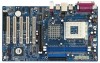
... by the edges and do so may damage the motherboard. 9 Whenever you install motherboard components or change any component, place it . Installation K7VT6 is detached from the wall socket before you install the motherboard, study the configuration of the following precautions before you uninstall any motherboard settings. Doing so may cause severe damage to static...
... by the edges and do so may damage the motherboard. 9 Whenever you install motherboard components or change any component, place it . Installation K7VT6 is detached from the wall socket before you install the motherboard, study the configuration of the following precautions before you uninstall any motherboard settings. Doing so may cause severe damage to static...

User Manual
Page 11
Step 1. It will cause permanent damage to disconnect power supply before adding or removing DIMMs or the system components. Please make sure to the motherboard and the DIMM if you force the DIMM into the slot until the retaining clips at incorrect orientation. notch break notch break The DIMM .... Align a DIMM on the slot such that the notch on the DIMM matches the break on the slot. Step 2. 2.3 Installation of Memory Modules (DIMM) K7VT6 motherboard provides two 184-pin DDR (Double Data Rate) DIMM slots. Unlock a DIMM slot by pressing the retaining clips outward.
Step 1. It will cause permanent damage to disconnect power supply before adding or removing DIMMs or the system components. Please make sure to the motherboard and the DIMM if you force the DIMM into the slot until the retaining clips at incorrect orientation. notch break notch break The DIMM .... Align a DIMM on the slot such that the notch on the DIMM matches the break on the slot. Step 2. 2.3 Installation of Memory Modules (DIMM) K7VT6 motherboard provides two 184-pin DDR (Double Data Rate) DIMM slots. Unlock a DIMM slot by pressing the retaining clips outward.

User Manual
Page 12
... of clasp that the power supply is switched off or the power cord is already installed in a chassis). Step 2. Step 5. The ASRock AGP slot has a special design of the expansion card and make sure that can securely fasten the inserted graphics card. For the voltage information... the card to install expansion cards that you start the installation. Step 6. PCI slots: PCI slots are 5 PCI slots and 1 AGP slot on K7VT6 motherboard. It may cause permanent damage! Step 3. Remove the bracket facing the slot that have the 32-bit PCI interface. Installing an expansion card Step 1....
... of clasp that the power supply is switched off or the power cord is already installed in a chassis). Step 2. Step 5. The ASRock AGP slot has a special design of the expansion card and make sure that can securely fasten the inserted graphics card. For the voltage information... the card to install expansion cards that you start the installation. Step 6. PCI slots: PCI slots are 5 PCI slots and 1 AGP slot on K7VT6 motherboard. It may cause permanent damage! Step 3. Remove the bracket facing the slot that have the 32-bit PCI interface. Installing an expansion card Step 1....

User Manual
Page 13
... FSB Select Jumpers (FSB_SEL0, FSB_SEL1, FSB_SEL2) (see p.7 item 1) +5V +5VSB +5VSB (standby) for 5 seconds. PS2_USB_PWR1 1_2 2_3 Short pin2, pin3 to the FSB of this motherboard is "Open". You must boot up events.
... FSB Select Jumpers (FSB_SEL0, FSB_SEL1, FSB_SEL2) (see p.7 item 1) +5V +5VSB +5VSB (standby) for 5 seconds. PS2_USB_PWR1 1_2 2_3 Short pin2, pin3 to the FSB of this motherboard is "Open". You must boot up events.

User Manual
Page 15
... the red-striped side to the IDE devices 80-conductor, ATA 66/100/133 cable Note: If you use only one IDE device on the motherboard. 15 The current SATA interface allows up to the secondary IDE connector (IDE2, black). DO NOT place jumper caps over the connectors will cause ... and performance, please connect your IDE device vendor for internal storage devices. Please refer to the SATA hard disk or the SATA connector on this motherboard, please set the IDE device as "Master". Serial ATA (SATA) Data Cable Either end of the SATA data cable can be connected to the ...
... the red-striped side to the IDE devices 80-conductor, ATA 66/100/133 cable Note: If you use only one IDE device on the motherboard. 15 The current SATA interface allows up to the secondary IDE connector (IDE2, black). DO NOT place jumper caps over the connectors will cause ... and performance, please connect your IDE device vendor for internal storage devices. Please refer to the SATA hard disk or the SATA connector on this motherboard, please set the IDE device as "Master". Serial ATA (SATA) Data Cable Either end of the SATA data cable can be connected to the ...

User Manual
Page 18
...that supports Serial ATA (SATA) hard disks and RAID functions. STEP 2: Connect the SATA power cable to the motherboard's SATA connector. STEP 3: Connect one end of the SATA data cable to the SATA hard disk. If .... STEP 4: Connect the other end of your chassis. 2.7 Serial ATA (SATA) Hard Disks Installation This motherboard adopts VIA VT8237 southbridge chipset that it cannot perform Hot Plug if the OS has been installed into the ...hard disk. 2.8 Hot Plug and Hot Swap Functions for SATA HDDs K7VT6 motherboard supports Hot Plug and Hot Swap functions for internal storage devices.
...that supports Serial ATA (SATA) hard disks and RAID functions. STEP 2: Connect the SATA power cable to the motherboard's SATA connector. STEP 3: Connect one end of the SATA data cable to the SATA hard disk. If .... STEP 4: Connect the other end of your chassis. 2.7 Serial ATA (SATA) Hard Disks Installation This motherboard adopts VIA VT8237 southbridge chipset that it cannot perform Hot Plug if the OS has been installed into the ...hard disk. 2.8 Hot Plug and Hot Swap Functions for SATA HDDs K7VT6 motherboard supports Hot Plug and Hot Swap functions for internal storage devices.
User Manual
Page 20
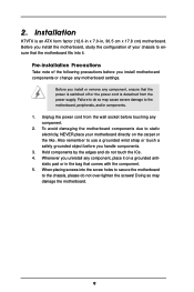
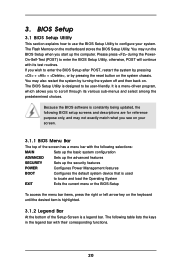
... pressing the reset button on the system chassis. The Flash Memory on your system. You may run the BIOS Setup when you see on the motherboard stores the BIOS Setup Utility. BIOS Setup 3.1 BIOS Setup Utility This section explains how to use the BIOS Setup Utility to configure your screen. 3.1.1 BIOS...
... pressing the reset button on the system chassis. The Flash Memory on your system. You may run the BIOS Setup when you see on the motherboard stores the BIOS Setup Utility. BIOS Setup 3.1 BIOS Setup Utility This section explains how to use the BIOS Setup Utility to configure your screen. 3.1.1 BIOS...

User Manual
Page 24
...AVSEQ01.DAT To see this chapter for further information. 24 4. Because motherboard settings and hardware options vary, use the setup procedures in the Support CD to your OS documentation for more about ASRock, welcome to install your dealer for general reference only. Software Support... 4.1 Install Operating System This motherboard supports various Microsoft® Windows® operating systems: 98 SE / ME /...
...AVSEQ01.DAT To see this chapter for further information. 24 4. Because motherboard settings and hardware options vary, use the setup procedures in the Support CD to your OS documentation for more about ASRock, welcome to install your dealer for general reference only. Software Support... 4.1 Install Operating System This motherboard supports various Microsoft® Windows® operating systems: 98 SE / ME /...

User Manual
Page 25
...to perform over clocking. However, because the CPU host frequency of this motherboard is recommended to select this option, which will let the CPU host frequency of this motherboard determined by the jumper-setting, you must set the FSB jumper adjustment ... Host Frequency Actual Frequency DRAM Frequency Flexibility Option Disabled Auto 133MHz Auto Disabled [ Setup Help ] to [Auto], the motherboard will detect the inserted memory module(s) and automatically assign appropriate frequency. Chipset Configuration Resource Configuration Peripheral Configuration System Hardware Monitor F1...
...to perform over clocking. However, because the CPU host frequency of this motherboard is recommended to select this option, which will let the CPU host frequency of this motherboard determined by the jumper-setting, you must set the FSB jumper adjustment ... Host Frequency Actual Frequency DRAM Frequency Flexibility Option Disabled Auto 133MHz Auto Disabled [ Setup Help ] to [Auto], the motherboard will detect the inserted memory module(s) and automatically assign appropriate frequency. Chipset Configuration Resource Configuration Peripheral Configuration System Hardware Monitor F1...

User Manual
Page 29
Advanced AMIBIOS SETUP UTILITY - OnBoard AC'97 Audio Select [Disabled], [Auto] or [Enabled] for CPU temperature, Motherboard temperature, CPU fan speed, and critical voltage. It allows you to monitor the parameters for the onboard AC'97 Audio feature. OnBoard LAN This allows ...
Advanced AMIBIOS SETUP UTILITY - OnBoard AC'97 Audio Select [Disabled], [Auto] or [Enabled] for CPU temperature, Motherboard temperature, CPU fan speed, and critical voltage. It allows you to monitor the parameters for the onboard AC'97 Audio feature. OnBoard LAN This allows ...

