
User Manual
Page 5
...(10/100 Ethernet), Supports Wake-On-LAN Hardware Monitor: CPU Temperature Sensing Motherboard Temperature Sensing CPU Overheat Shutdown to Protect CPU Life (ASRock U-COP)(see CAUTION 1) CPU Fan Tachometer Chassis Fan Tachometer Voltage Monitoring: +12V, +5V, +3.3V, Vcore PCI slots: 5 Slots...slot: 1 AGP Slot, Supports 1.5V, 8X/4X AGP Card (see CAUTION 2) USB 2.0: 8 USB 2.0 ports: include 6 ready-to-use USB 2.0 ports on the rear panel, plus one on-board header supporting 2 extra USB 2.0 ports (see CAUTION 3) ASRock I/O PlusTM: 1 PS/2 Mouse Port, 1 PS/2 Keyboard Port, 1 Serial Port...
...(10/100 Ethernet), Supports Wake-On-LAN Hardware Monitor: CPU Temperature Sensing Motherboard Temperature Sensing CPU Overheat Shutdown to Protect CPU Life (ASRock U-COP)(see CAUTION 1) CPU Fan Tachometer Chassis Fan Tachometer Voltage Monitoring: +12V, +5V, +3.3V, Vcore PCI slots: 5 Slots...slot: 1 AGP Slot, Supports 1.5V, 8X/4X AGP Card (see CAUTION 2) USB 2.0: 8 USB 2.0 ports: include 6 ready-to-use USB 2.0 ports on the rear panel, plus one on-board header supporting 2 extra USB 2.0 ports (see CAUTION 3) ASRock I/O PlusTM: 1 PS/2 Mouse Port, 1 PS/2 Keyboard Port, 1 Serial Port...

User Manual
Page 6
...OS: AMI legal BIOS, Supports "Plug and Play", ACPI 1.1 Compliance Wake-Up Events, SMBIOS 2.3.1 Support, CPU Frequency Stepless Control (only for USB 2.0 works fine under Microsoft® Windows® 98/ME. Power Management for advanced users' reference, see CAUTION 4) Microsoft® Windows®... to perform over clocking. To improve heat dissipation, remember to Microsoft® official document at http://www.microsoft.com/whdc/hwdev/bus/USB/USB2support.mspx 4. See page 13 for "CPU Host Frequency" configuration. 6 Do NOT use a 3.3V AGP card on the motherboard...
...OS: AMI legal BIOS, Supports "Plug and Play", ACPI 1.1 Compliance Wake-Up Events, SMBIOS 2.3.1 Support, CPU Frequency Stepless Control (only for USB 2.0 works fine under Microsoft® Windows® 98/ME. Power Management for advanced users' reference, see CAUTION 4) Microsoft® Windows®... to perform over clocking. To improve heat dissipation, remember to Microsoft® official document at http://www.microsoft.com/whdc/hwdev/bus/USB/USB2support.mspx 4. See page 13 for "CPU Host Frequency" configuration. 6 Do NOT use a 3.3V AGP card on the motherboard...

User Manual
Page 7
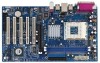
...pin module) ATXPWR1 30.5cm (12.0 in) 29 28 USB 2.0 T: USB2 B: USB3 USB 2.0 T: USB0 Top: RJ-45 B: USB1 USB 2.0 T: USB4 1 B: USB5 JUSB45 VIA KT400A CHIPSET Top: Line In Center: Line Out Bottom: Mic In 27 2MB BIOS AGP 8X K7VT4A PRO LAN PHY SUPER I/O 1.5V_AGP1 IDE1 IDE2 7 8 9...SATA2) 14 Power LED Connector (PWR_LED1) 15 Chassis Fan Connector (CHA_FAN1) 16 System Panel Connector (PANEL1) 17 Chassis Speaker Connector (SPEAKER 1) 18 USB 2.0 Connector (USB67, Blue) 19 Floppy Connector (FLOPPY1) 20 Internal Audio Connector: CD1 (Black) 21 Internal Audio Connector: AUX1 (White) 22 ...
...pin module) ATXPWR1 30.5cm (12.0 in) 29 28 USB 2.0 T: USB2 B: USB3 USB 2.0 T: USB0 Top: RJ-45 B: USB1 USB 2.0 T: USB4 1 B: USB5 JUSB45 VIA KT400A CHIPSET Top: Line In Center: Line Out Bottom: Mic In 27 2MB BIOS AGP 8X K7VT4A PRO LAN PHY SUPER I/O 1.5V_AGP1 IDE1 IDE2 7 8 9...SATA2) 14 Power LED Connector (PWR_LED1) 15 Chassis Fan Connector (CHA_FAN1) 16 System Panel Connector (PANEL1) 17 Chassis Speaker Connector (SPEAKER 1) 18 USB 2.0 Connector (USB67, Blue) 19 Floppy Connector (FLOPPY1) 20 Internal Audio Connector: CD1 (Black) 21 Internal Audio Connector: AUX1 (White) 22 ...

User Manual
Page 8
1.4 ASRock I/O PlusTM 1 2 3 4 5 11 10 9 1 Parallel Port 2 RJ-45 Port 3 Line In (Light Blue) 4 Line Out (Lime) 5 Microphone (Pink) 6 2 x Shared USB 2.0 Port (USB4, USB5) 8 7 6 7 2 x USB 2.0 Port (USB0, USB1) 8 2 x USB 2.0 Port (USB2, USB3) 9 Serial Port: COM1 10 PS/2 Keyboard Port (Purple) 11 PS/2 Mouse Port (Green) 8
1.4 ASRock I/O PlusTM 1 2 3 4 5 11 10 9 1 Parallel Port 2 RJ-45 Port 3 Line In (Light Blue) 4 Line Out (Lime) 5 Microphone (Pink) 6 2 x Shared USB 2.0 Port (USB4, USB5) 8 7 6 7 2 x USB 2.0 Port (USB0, USB1) 8 2 x USB 2.0 Port (USB2, USB3) 9 Serial Port: COM1 10 PS/2 Keyboard Port (Purple) 11 PS/2 Mouse Port (Green) 8

User Manual
Page 13
... the CMOS when you just finish updating the BIOS, you must adjust "FSB Select Jumpers" according to short the Clear CMOS jumper for PS/2 or USB wake up the system first, and then shut it requires 2 Amp and higher standby current provided by jumper-setting. When the jumper cap is placed...
... the CMOS when you just finish updating the BIOS, you must adjust "FSB Select Jumpers" according to short the Clear CMOS jumper for PS/2 or USB wake up the system first, and then shut it requires 2 Amp and higher standby current provided by jumper-setting. When the jumper cap is placed...

User Manual
Page 16
... cable that allows convenient connection and control of audio devices. 16 O U T- O U T- USB 2.0 Header (9-pin USB67) (see p.7 item 21) AUX1 CD1 These connectors allow you 6 ready-to-use USB 2.0 ports on ASRock I/O PlusTM will not be able to function. L GND A U D - R MIC-POWER... MIC This is shared with the USB 2.0 ports 4,5 on each drive. Shared USB 2.0 Header (9-pin JUSB45) (see p.7 No. 24) GND +5VA BACKOUT-R ...
... cable that allows convenient connection and control of audio devices. 16 O U T- O U T- USB 2.0 Header (9-pin USB67) (see p.7 item 21) AUX1 CD1 These connectors allow you 6 ready-to-use USB 2.0 ports on ASRock I/O PlusTM will not be able to function. L GND A U D - R MIC-POWER... MIC This is shared with the USB 2.0 ports 4,5 on each drive. Shared USB 2.0 Header (9-pin JUSB45) (see p.7 No. 24) GND +5VA BACKOUT-R ...

User Manual
Page 26
...SETUP UTILITY - AGP Aperture Size It refers to a section of the PCI memory address range used to leave this field as default. USB Device Legacy Support Use this to speed up the V-Link speed. The default value is recommended to adjust the means of memory accessing....It is [Normal]. 26 VERSION 3.31a Chipset Configuration [ Setup Help ] AGP Mode AGP Aperture Size AGP Fast Write PCI Delay Transaction USB Controller USB Device Legacy Support DRAM CAS# Latency V-Link Speed Over Vcore Voltage VCCM Voltage AGP Voltage Auto 64MB Disabled Disabled Enabled Disabled Auto Normal Disabled...
...SETUP UTILITY - AGP Aperture Size It refers to a section of the PCI memory address range used to leave this field as default. USB Device Legacy Support Use this to speed up the V-Link speed. The default value is recommended to adjust the means of memory accessing....It is [Normal]. 26 VERSION 3.31a Chipset Configuration [ Setup Help ] AGP Mode AGP Aperture Size AGP Fast Write PCI Delay Transaction USB Controller USB Device Legacy Support DRAM CAS# Latency V-Link Speed Over Vcore Voltage VCCM Voltage AGP Voltage Auto 64MB Disabled Disabled Enabled Disabled Auto Normal Disabled...

Quick Installation Guide
Page 2
...Serial ATA Connector (SATA2) 14 Power LED Connector (PWR_LED1) 15 Chassis Fan Connector (CHA_FAN1) 16 System Panel Connector (PANEL1) 17 Chassis Speaker Connector (SPEAKER 1) 18 USB 2.0 Connector (USB67, Blue) 19 Floppy Connector (FLOPPY1) 20 Internal Audio Connector: CD1 (Black) 21 Internal Audio Connector: AUX1 (White) 22 Clear CMOS Jumper (... 23 JR1 / JL1 Jumpers 24 Front Panel Audio Connector (AUDIO1) 25 PCI Slots (PCI1- 5) 26 Game Port Connector (GAME1) 27 Flash Memory 28 Shared USB 2.0 Header (JUSB45, Blue) 29 J1 Jumper (FID0, FID1, FID2, FID3, FID4) 2 ASRock K7VT4A Pro Motherboard
...Serial ATA Connector (SATA2) 14 Power LED Connector (PWR_LED1) 15 Chassis Fan Connector (CHA_FAN1) 16 System Panel Connector (PANEL1) 17 Chassis Speaker Connector (SPEAKER 1) 18 USB 2.0 Connector (USB67, Blue) 19 Floppy Connector (FLOPPY1) 20 Internal Audio Connector: CD1 (Black) 21 Internal Audio Connector: AUX1 (White) 22 Clear CMOS Jumper (... 23 JR1 / JL1 Jumpers 24 Front Panel Audio Connector (AUDIO1) 25 PCI Slots (PCI1- 5) 26 Game Port Connector (GAME1) 27 Flash Memory 28 Shared USB 2.0 Header (JUSB45, Blue) 29 J1 Jumper (FID0, FID1, FID2, FID3, FID4) 2 ASRock K7VT4A Pro Motherboard

Quick Installation Guide
Page 3
ASRock I/O PlusTM 1 Parallel Port 2 RJ-45 Port 3 Line In (Light Blue) 4 Line Out (Lime) 5 Microphone (Pink) 6 2 x Shared USB 2.0 Port (USB4, USB5) 7 2 x USB 2.0 Port (USB0, USB1) 8 2 x USB 2.0 Port (USB2, USB3) 9 Serial Port: COM1 10 PS/2 Keyboard Port (Purple) 11 PS/2 Mouse Port (Green) English 3 ASRock K7VT4A Pro Motherboard
ASRock I/O PlusTM 1 Parallel Port 2 RJ-45 Port 3 Line In (Light Blue) 4 Line Out (Lime) 5 Microphone (Pink) 6 2 x Shared USB 2.0 Port (USB4, USB5) 7 2 x USB 2.0 Port (USB0, USB1) 8 2 x USB 2.0 Port (USB2, USB3) 9 Serial Port: COM1 10 PS/2 Keyboard Port (Purple) 11 PS/2 Mouse Port (Green) English 3 ASRock K7VT4A Pro Motherboard

Quick Installation Guide
Page 5
...10/100 Ethernet), Supports Wake-On-LAN Hardware Monitor: CPU Temperature Sensing Motherboard Temperature Sensing CPU Overheat Shutdown to Protect CPU Life (ASRock U-COP)(see CAUTION 1) CPU Fan Tachometer Chassis Fan Tachometer Voltage Monitoring: +12V, +5V, +3.3V, Vcore PCI slots: ...supporting 2 extra USB 2.0 ports (see CAUTION 3) ASRock I/O PlusTM: 1 PS/2 Mouse Port, 1 PS/2 Keyboard Port, 1 Serial Port: COM1, 1 Parallel Port (ECP/EPP Support) 6 ready-to-use USB 2.0 Ports, 1 RJ-45 Port, Audio Jack: Line In / Line Out / Microphone English 5 ASRock K7VT4A Pro Motherboard PC3200 (...
...10/100 Ethernet), Supports Wake-On-LAN Hardware Monitor: CPU Temperature Sensing Motherboard Temperature Sensing CPU Overheat Shutdown to Protect CPU Life (ASRock U-COP)(see CAUTION 1) CPU Fan Tachometer Chassis Fan Tachometer Voltage Monitoring: +12V, +5V, +3.3V, Vcore PCI slots: ...supporting 2 extra USB 2.0 ports (see CAUTION 3) ASRock I/O PlusTM: 1 PS/2 Mouse Port, 1 PS/2 Keyboard Port, 1 Serial Port: COM1, 1 Parallel Port (ECP/EPP Support) 6 ready-to-use USB 2.0 Ports, 1 RJ-45 Port, Audio Jack: Line In / Line Out / Microphone English 5 ASRock K7VT4A Pro Motherboard PC3200 (...

Quick Installation Guide
Page 6
...document at http://www.microsoft.com/whdc/hwdev/bus/USB/USB2support.mspx 4. It may cause the instability of "User Manual" in BIOS. Although this motherboard offers stepless control, it back again. English 6 ASRock K7VT4A Pro Motherboard To improve heat dissipation, remember to the ...OS: AMI legal BIOS, Supports "Plug and Play", ACPI 1.1 Compliance Wake-Up Events, SMBIOS 2.3.1 Support, CPU Frequency Stepless Control (only for USB 2.0 works fine under Microsoft® Windows® 98/ME. Power Management for advanced users' reference, see CAUTION 4) Microsoft® Windows®...
...document at http://www.microsoft.com/whdc/hwdev/bus/USB/USB2support.mspx 4. It may cause the instability of "User Manual" in BIOS. Although this motherboard offers stepless control, it back again. English 6 ASRock K7VT4A Pro Motherboard To improve heat dissipation, remember to the ...OS: AMI legal BIOS, Supports "Plug and Play", ACPI 1.1 Compliance Wake-Up Events, SMBIOS 2.3.1 Support, CPU Frequency Stepless Control (only for USB 2.0 works fine under Microsoft® Windows® 98/ME. Power Management for advanced users' reference, see CAUTION 4) Microsoft® Windows®...

Quick Installation Guide
Page 10
... the Support CD for 5 seconds. After shorting the Clear CMOS jumper, please remove the jumper cap. English 10 ASRock K7VT4A Pro Motherboard PS2_USB_PWR1 Short pin2, pin3 to enable (see p.2 item 1) +5VSB (standby) for PS/2 or USB wake up the system first, and then shut it requires 2 Amp and higher standby current provided by power...
... the Support CD for 5 seconds. After shorting the Clear CMOS jumper, please remove the jumper cap. English 10 ASRock K7VT4A Pro Motherboard PS2_USB_PWR1 Short pin2, pin3 to enable (see p.2 item 1) +5VSB (standby) for PS/2 or USB wake up the system first, and then shut it requires 2 Amp and higher standby current provided by power...

Quick Installation Guide
Page 12
...p.2 item 21) AUX1 These connectors allow you 6 ready-to-use USB 2.0 ports on the drive. USB 2.0 Header (9-pin USB67) (see p.2 item 24) This is shared with the USB 2.0 ports 4,5 on ASRock I/O PlusTM. English 12 ASRock K7VT4A Pro Motherboard Then connect the white end of SATA power cable to the ...power supply. If the rear USB ports are not sufficient, this connector (JUSB45), the USB ports 4,5 on ASRock I /O PlusTM provides you to support 2 extra USB 2.0 ports. When using the front panel USB ports by attaching the front panel USB cable to this USB 2.0 header is available to ...
...p.2 item 21) AUX1 These connectors allow you 6 ready-to-use USB 2.0 ports on the drive. USB 2.0 Header (9-pin USB67) (see p.2 item 24) This is shared with the USB 2.0 ports 4,5 on ASRock I/O PlusTM. English 12 ASRock K7VT4A Pro Motherboard Then connect the white end of SATA power cable to the ...power supply. If the rear USB ports are not sufficient, this connector (JUSB45), the USB ports 4,5 on ASRock I /O PlusTM provides you to support 2 extra USB 2.0 ports. When using the front panel USB ports by attaching the front panel USB cable to this USB 2.0 header is available to ...


