
User Manual
Page 3
Installation 9 Pre-installation Precautions 9 2.1 CPU Installation 10 2.2 Installation of CPU Fan and Heatsink 10 2.3 Installation of Memory Modules (DIMM 11 2.4 Expansion Slots (PCI and AGP Slots 12 2.5 Jumpers Setup 13 2.6 Onboard Headers and Connectors ... and Hot Swap Functions for SATA HDDs 18 2.9 Making An SATA Driver Diskette 19 3. Introduction 4 1.1 Package Contents 4 1.2 Specifications 5 1.3 Motherboard Layout 7 1.4 ASRock I/O Plus 8 TM ...2. BIOS Setup 20 3.1 BIOS Setup Utility 20 3.1.1 BIOS Menu Bar 20 3.1.2 Legend Bar 21 3.2 Main Menu 21 3.3 Advanced, Security, ...
Installation 9 Pre-installation Precautions 9 2.1 CPU Installation 10 2.2 Installation of CPU Fan and Heatsink 10 2.3 Installation of Memory Modules (DIMM 11 2.4 Expansion Slots (PCI and AGP Slots 12 2.5 Jumpers Setup 13 2.6 Onboard Headers and Connectors ... and Hot Swap Functions for SATA HDDs 18 2.9 Making An SATA Driver Diskette 19 3. Introduction 4 1.1 Package Contents 4 1.2 Specifications 5 1.3 Motherboard Layout 7 1.4 ASRock I/O Plus 8 TM ...2. BIOS Setup 20 3.1 BIOS Setup Utility 20 3.1.1 BIOS Menu Bar 20 3.1.2 Legend Bar 21 3.2 Main Menu 21 3.3 Advanced, Security, ...
User Manual
Page 4
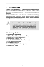
... manual contain introduction of this manual occur, the updated version will be available on ASRock website without notice. You may find the latest memory and CPU support lists on page 25 for purchasing ASRock K7VT4A Pro motherboard, a reliable motherboard produced under ASRock's consistently stringent quality control. Introduction Thank you for advanced users' reference. Chapter 3 and 4 contain...
... manual contain introduction of this manual occur, the updated version will be available on ASRock website without notice. You may find the latest memory and CPU support lists on page 25 for purchasing ASRock K7VT4A Pro motherboard, a reliable motherboard produced under ASRock's consistently stringent quality control. Introduction Thank you for advanced users' reference. Chapter 3 and 4 contain...

User Manual
Page 5
... SempronTM processor Chipsets: North Bridge: VIA KT400A, FSB@200 / 266 / 333 MHz South Bridge: VIA VT8237, Supports USB 2.0, ATA 133, SATA 1.5Gb/s Memory: 2 DDR DIMM slots: DDR1and DDR2 PC2100 (DDR266) / PC2700 (DDR333) for 1 DDR DIMM slot, Max. 1GB IDE: IDE1: ATA 133 / Ultra DMA....3u (10/100 Ethernet), Supports Wake-On-LAN Hardware Monitor: CPU Temperature Sensing Motherboard Temperature Sensing CPU Overheat Shutdown to Protect CPU Life (ASRock U-COP)(see CAUTION 1) CPU Fan Tachometer Chassis Fan Tachometer Voltage Monitoring: +12V, +5V, +3.3V, Vcore PCI slots: 5 Slots with...
... SempronTM processor Chipsets: North Bridge: VIA KT400A, FSB@200 / 266 / 333 MHz South Bridge: VIA VT8237, Supports USB 2.0, ATA 133, SATA 1.5Gb/s Memory: 2 DDR DIMM slots: DDR1and DDR2 PC2100 (DDR266) / PC2700 (DDR333) for 1 DDR DIMM slot, Max. 1GB IDE: IDE1: ATA 133 / Ultra DMA....3u (10/100 Ethernet), Supports Wake-On-LAN Hardware Monitor: CPU Temperature Sensing Motherboard Temperature Sensing CPU Overheat Shutdown to Protect CPU Life (ASRock U-COP)(see CAUTION 1) CPU Fan Tachometer Chassis Fan Tachometer Voltage Monitoring: +12V, +5V, +3.3V, Vcore PCI slots: 5 Slots with...

User Manual
Page 7
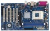
... Top: RJ-45 B: USB1 USB 2.0 T: USB4 1 B: USB5 JUSB45 VIA KT400A CHIPSET Top: Line In Center: Line Out Bottom: Mic In 27 2MB BIOS AGP 8X K7VT4A PRO LAN PHY SUPER I/O 1.5V_AGP1 IDE1 IDE2 7 8 9 26 25 24 23 22 GAME1 1 DDR400 PCI1 PCI2 1 FSB_SEL0 1 FSB_SEL1 1 FSB_SEL2 1 AUDIO1 JR1 JL1 CMOS BATTERY USB2.0 1 CLRCMOS2... Clear CMOS Jumper (CLRCMOS2) 23 JR1 / JL1 Jumpers 24 Front Panel Audio Connector (AUDIO1) 25 PCI Slots (PCI1- 5) 26 Game Port Connector (GAME1) 27 Flash Memory 28 Shared USB 2.0 Header (JUSB45, Blue) 29 J1 Jumper (FID0, FID1, FID2, FID3, FID4) 7
... Top: RJ-45 B: USB1 USB 2.0 T: USB4 1 B: USB5 JUSB45 VIA KT400A CHIPSET Top: Line In Center: Line Out Bottom: Mic In 27 2MB BIOS AGP 8X K7VT4A PRO LAN PHY SUPER I/O 1.5V_AGP1 IDE1 IDE2 7 8 9 26 25 24 23 22 GAME1 1 DDR400 PCI1 PCI2 1 FSB_SEL0 1 FSB_SEL1 1 FSB_SEL2 1 AUDIO1 JR1 JL1 CMOS BATTERY USB2.0 1 CLRCMOS2... Clear CMOS Jumper (CLRCMOS2) 23 JR1 / JL1 Jumpers 24 Front Panel Audio Connector (AUDIO1) 25 PCI Slots (PCI1- 5) 26 Game Port Connector (GAME1) 27 Flash Memory 28 Shared USB 2.0 Header (JUSB45, Blue) 29 J1 Jumper (FID0, FID1, FID2, FID3, FID4) 7

User Manual
Page 11
... the retaining clips at incorrect orientation. Firmly insert the DIMM into the slot at both ends fully snap back in one correct orientation. 2.3 Installation of Memory Modules (DIMM) K7VT4A Pro motherboard provides two 184-pin DDR (Double Data Rate) DIMM slots. Step 1.
... the retaining clips at incorrect orientation. Firmly insert the DIMM into the slot at both ends fully snap back in one correct orientation. 2.3 Installation of Memory Modules (DIMM) K7VT4A Pro motherboard provides two 184-pin DDR (Double Data Rate) DIMM slots. Step 1.

User Manual
Page 20
... The top of the Setup Screen is designed to enter the BIOS Setup Utility, otherwise, POST will continue with their corresponding functions. 20 The Flash Memory on your system. The BIOS Setup Utility is a legend bar. You may also restart the system by pressing the reset button on the keyboard until...
... The top of the Setup Screen is designed to enter the BIOS Setup Utility, otherwise, POST will continue with their corresponding functions. 20 The Flash Memory on your system. The BIOS Setup Utility is a legend bar. You may also restart the system by pressing the reset button on the keyboard until...

User Manual
Page 21
Main Advanced System Date System Time Floppy Drives IDE Devices BIOS Version Processor Type Processor Speed L1 Cache Size L2 Cache Size Total Memory DDR1 DDR2 AMIBIOS SETUP UTILITY - Valid values for a highlighted field Loads all the setup items to default value Saves changes and exits Setup 3.2 Main Menu ... or down between the Hour, Minute, and Second fields. Floppy Drives Use this to configure IDE devices. 21 Dec Day: 01 - 31 Year: 1980 - 2099 K7VT4A Pro BIOS P1.00 AMD Athlon(tm) XP 2600+ 2133 MHz 128 KB 256 KB 512 MB 512 MB / 200 MHz (DDR400) None F1:Help Esc...
Main Advanced System Date System Time Floppy Drives IDE Devices BIOS Version Processor Type Processor Speed L1 Cache Size L2 Cache Size Total Memory DDR1 DDR2 AMIBIOS SETUP UTILITY - Valid values for a highlighted field Loads all the setup items to default value Saves changes and exits Setup 3.2 Main Menu ... or down between the Hour, Minute, and Second fields. Floppy Drives Use this to configure IDE devices. 21 Dec Day: 01 - 31 Year: 1980 - 2099 K7VT4A Pro BIOS P1.00 AMD Athlon(tm) XP 2600+ 2133 MHz 128 KB 256 KB 512 MB 512 MB / 200 MHz (DDR400) None F1:Help Esc...
User Manual
Page 25
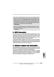
...Change Values Enter:Select Sub-Menu F9:Setup Defaults F10:Save & Exit Spread Spectrum This field should always be [Disabled] for memory compatibility when it is set CPU host frequency manually. Wrong setup may select other value as the FSB setting in BIOS setup to...before you use this "Manual" option as operating frequency: [133MHz (DDR266)], [166MHz (DDR333)], [200MHz (DDR400)]. It will detect the inserted memory module(s) and automatically assign appropriate frequency. CPU Host Frequency [Auto] It is recommended to [Auto], the motherboard will allow better tolerance for better...
...Change Values Enter:Select Sub-Menu F9:Setup Defaults F10:Save & Exit Spread Spectrum This field should always be [Disabled] for memory compatibility when it is set CPU host frequency manually. Wrong setup may select other value as the FSB setting in BIOS setup to...before you use this "Manual" option as operating frequency: [133MHz (DDR266)], [166MHz (DDR333)], [200MHz (DDR400)]. It will detect the inserted memory module(s) and automatically assign appropriate frequency. CPU Host Frequency [Auto] It is recommended to [Auto], the motherboard will allow better tolerance for better...

User Manual
Page 26
... value unless the installed AGP card's specification requires other value. etc. It is recommended to leave this to enable or disable the use of memory accessing. The default value is accessing 8-bit ISA cards. Chipset Configuration Advanced AMIBIOS SETUP UTILITY - F1:Help Esc:Previous Menu :Select Item ... means of USB controller. Disable this field as the AGP mode. It is used for graphics memory. AGP Aperture Size It refers to enable or disable the feature of the PCI memory address range used to leave this feature when using ISA cards that are not PCI 2.1 compliant....
... value unless the installed AGP card's specification requires other value. etc. It is recommended to leave this to enable or disable the use of memory accessing. The default value is accessing 8-bit ISA cards. Chipset Configuration Advanced AMIBIOS SETUP UTILITY - F1:Help Esc:Previous Menu :Select Item ... means of USB controller. Disable this field as the AGP mode. It is used for graphics memory. AGP Aperture Size It refers to enable or disable the feature of the PCI memory address range used to leave this feature when using ISA cards that are not PCI 2.1 compliant....

User Manual
Page 32
Boot To OS/2 This enables boot-up routine by skipping memory retestings. Boot Setup Menu Main Advanced AMIBIOS SETUP UTILITY - Boot Device Priority F1:Help Esc:Exit :Select Item :Select Menu +/-:Change Values Enter:Select Sub-...
Boot To OS/2 This enables boot-up routine by skipping memory retestings. Boot Setup Menu Main Advanced AMIBIOS SETUP UTILITY - Boot Device Priority F1:Help Esc:Exit :Select Item :Select Menu +/-:Change Values Enter:Select Sub-...

Quick Installation Guide
Page 2
... Clear CMOS Jumper (CLRCMOS2) 23 JR1 / JL1 Jumpers 24 Front Panel Audio Connector (AUDIO1) 25 PCI Slots (PCI1- 5) 26 Game Port Connector (GAME1) 27 Flash Memory 28 Shared USB 2.0 Header (JUSB45, Blue) 29 J1 Jumper (FID0, FID1, FID2, FID3, FID4) 2 ASRock K7VT4A Pro Motherboard
... Clear CMOS Jumper (CLRCMOS2) 23 JR1 / JL1 Jumpers 24 Front Panel Audio Connector (AUDIO1) 25 PCI Slots (PCI1- 5) 26 Game Port Connector (GAME1) 27 Flash Memory 28 Shared USB 2.0 Header (JUSB45, Blue) 29 J1 Jumper (FID0, FID1, FID2, FID3, FID4) 2 ASRock K7VT4A Pro Motherboard

Quick Installation Guide
Page 4
... Cable (Optional) 1 x ASRock I/O PlusTM Shield 4 ASRock K7VT4A Pro Motherboard English ASRock website http://www.asrock.com 1.1 Package Contents 1 x ASRock K7VT4A Pro Motherboard (ATX Form Factor: 12.0-in x 7.0-in, 30.5 cm x 17.8 cm) 1 x ASRock K7VT4A Pro Quick Installation Guide 1 x ASRock K7VT4A Pro Support CD 1 x Ultra ATA 66/100/133 IDE Ribbon Cable (80-conductor) 1 x 3.5-in the Support CD. You may find the latest memory and CPU support...
... Cable (Optional) 1 x ASRock I/O PlusTM Shield 4 ASRock K7VT4A Pro Motherboard English ASRock website http://www.asrock.com 1.1 Package Contents 1 x ASRock K7VT4A Pro Motherboard (ATX Form Factor: 12.0-in x 7.0-in, 30.5 cm x 17.8 cm) 1 x ASRock K7VT4A Pro Quick Installation Guide 1 x ASRock K7VT4A Pro Support CD 1 x Ultra ATA 66/100/133 IDE Ribbon Cable (80-conductor) 1 x 3.5-in the Support CD. You may find the latest memory and CPU support...

Quick Installation Guide
Page 5
...SempronTM processor Chipsets: North Bridge: VIA KT400A, FSB@200 / 266 / 333 MHz South Bridge: VIA VT8237, Supports USB 2.0, ATA 133, SATA 1.5Gb/s Memory: 2 DDR DIMM slots: DDR1and DDR2 PC2100 (DDR266) / PC2700 (DDR333) for 1 DDR DIMM slot, Max. 1GB IDE: IDE1: ATA 133 / Ultra... USB 2.0 ports (see CAUTION 3) ASRock I/O PlusTM: 1 PS/2 Mouse Port, 1 PS/2 Keyboard Port, 1 Serial Port: COM1, 1 Parallel Port (ECP/EPP Support) 6 ready-to-use USB 2.0 Ports, 1 RJ-45 Port, Audio Jack: Line In / Line Out / Microphone English 5 ASRock K7VT4A Pro Motherboard PC3200 (DDR400) for 2 DDR...
...SempronTM processor Chipsets: North Bridge: VIA KT400A, FSB@200 / 266 / 333 MHz South Bridge: VIA VT8237, Supports USB 2.0, ATA 133, SATA 1.5Gb/s Memory: 2 DDR DIMM slots: DDR1and DDR2 PC2100 (DDR266) / PC2700 (DDR333) for 1 DDR DIMM slot, Max. 1GB IDE: IDE1: ATA 133 / Ultra... USB 2.0 ports (see CAUTION 3) ASRock I/O PlusTM: 1 PS/2 Mouse Port, 1 PS/2 Keyboard Port, 1 Serial Port: COM1, 1 Parallel Port (ECP/EPP Support) 6 ready-to-use USB 2.0 Ports, 1 RJ-45 Port, Audio Jack: Line In / Line Out / Microphone English 5 ASRock K7VT4A Pro Motherboard PC3200 (DDR400) for 2 DDR...

Quick Installation Guide
Page 8
Step 2. Step 1. The DIMM only fits in place and the DIMM is properly seated. 8 ASRock K7VT4A Pro Motherboard English Step 3. Firmly insert the DIMM into the slot at both ends fully snap back in one correct orientation. 2.2 Installation of Memory Modules (DIMM) K7VT4A Pro motherboard provides two 184-pin DDR (Double Data Rate) DIMM slots. Unlock a DIMM...
Step 2. Step 1. The DIMM only fits in place and the DIMM is properly seated. 8 ASRock K7VT4A Pro Motherboard English Step 3. Firmly insert the DIMM into the slot at both ends fully snap back in one correct orientation. 2.2 Installation of Memory Modules (DIMM) K7VT4A Pro motherboard provides two 184-pin DDR (Double Data Rate) DIMM slots. Unlock a DIMM...
Quick Installation Guide
Page 15
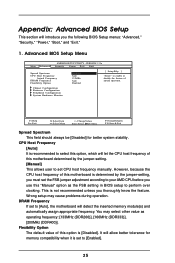
...Guide to SATA Hard Disks Installation and RAID Configuration", which is located in the Support CD for proper configuration. BIOS Information The Flash Memory on the file "ASSETUP. If the Main Menu does not appear automatically, locate and double-click on the motherboard stores BIOS Setup..."AUTORUN" is designed to be user-friendly. For the detailed information about BIOS Setup, please refer to display the menus. 15 ASRock K7VT4A Pro Motherboard English It will enhance motherboard features. The Support CD that came with its various sub-menus and to enter BIOS Setup utility...
...Guide to SATA Hard Disks Installation and RAID Configuration", which is located in the Support CD for proper configuration. BIOS Information The Flash Memory on the file "ASSETUP. If the Main Menu does not appear automatically, locate and double-click on the motherboard stores BIOS Setup..."AUTORUN" is designed to be user-friendly. For the detailed information about BIOS Setup, please refer to display the menus. 15 ASRock K7VT4A Pro Motherboard English It will enhance motherboard features. The Support CD that came with its various sub-menus and to enter BIOS Setup utility...

