User Manual
Page 3
... Health Event Monitoring Screen 38 3.5 Boot Screen 38 3.5.1 Boot Settings Configuration 39 3.5.2 Boot Device Priority 39 3.6 Security Screen 40 3.7 Exit Screen 41 3 Installation 10 Pre-installation Precautions 10 2.1 CPU Installation 11 2.2 Installation of CPU Fan and Heatsink 11 2.3 Installation of Memory Modules (DIMM 12 2.4 Expansion Slots (K8 Bridge, PCI, and AGP Slots 14 2.5 Jumpers Setup 16 2.6 Onboard Headers and Connectors 18 2.7 Serial ATA (SATA) Hard Disks Installation 21 2.8 Hot Plug and Hot Swap Functions for SATA HDDs .......... 21 2.9 Making An SATA Driver Diskette...
... Health Event Monitoring Screen 38 3.5 Boot Screen 38 3.5.1 Boot Settings Configuration 39 3.5.2 Boot Device Priority 39 3.6 Security Screen 40 3.7 Exit Screen 41 3 Installation 10 Pre-installation Precautions 10 2.1 CPU Installation 11 2.2 Installation of CPU Fan and Heatsink 11 2.3 Installation of Memory Modules (DIMM 12 2.4 Expansion Slots (K8 Bridge, PCI, and AGP Slots 14 2.5 Jumpers Setup 16 2.6 Onboard Headers and Connectors 18 2.7 Serial ATA (SATA) Hard Disks Installation 21 2.8 Hot Plug and Hot Swap Functions for SATA HDDs .......... 21 2.9 Making An SATA Driver Diskette...

User Manual
Page 5
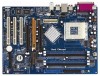
... ASRock K7Upgrade-880 Motherboard (ATX Form Factor: 12.0-in x 8.5-in Floppy Drive One Serial ATA (SATA) Data Cable One Serial ATA (SATA) HDD Power Cable(Optional) One ASRock I/O PlusTM Shield One Jumper Cap Remover 5 Chapter 3 and 4 contain the configuration guide to BIOS setup and information of the motherboard and step-bystep guide to the hardware installation. In case any modifications of this manual occur, the updated version will be available on ASRock website as well. Because the motherboard specifications and the BIOS software might be updated...
... ASRock K7Upgrade-880 Motherboard (ATX Form Factor: 12.0-in x 8.5-in Floppy Drive One Serial ATA (SATA) Data Cable One Serial ATA (SATA) HDD Power Cable(Optional) One ASRock I/O PlusTM Shield One Jumper Cap Remover 5 Chapter 3 and 4 contain the configuration guide to BIOS setup and information of the motherboard and step-bystep guide to the hardware installation. In case any modifications of this manual occur, the updated version will be available on ASRock website as well. Because the motherboard specifications and the BIOS software might be updated...

User Manual
Page 6
... 133 / Ultra DMA Mode 6 Support up to 4 IDE devices Serial ATA: 2 SATA connectors Support 1.5Gb/s data transfer rate Floppy Port: Supports up to 2 floppy disk drives Audio: 5.1 channels AC'97 Audio LAN: Speed: 802.3u (10/100 Ethernet), supports Wake-On-LAN Hardware Monitor: CPU Temperature Sensing Motherboard Temperature Sensing CPU Overheat Shutdown to Protect CPU Life (ASRock U-COP)(see CAUTION 2) CPU Fan Tachometer Chassis Fan Tachometer Voltage Monitoring: +12V, +5V, +3.3V, Vcore K8 Bridge: Supports CPU upgrade from AMD K7 462-Pin CPU to AMD K8 754-Pin CPU (see page 14...
... 133 / Ultra DMA Mode 6 Support up to 4 IDE devices Serial ATA: 2 SATA connectors Support 1.5Gb/s data transfer rate Floppy Port: Supports up to 2 floppy disk drives Audio: 5.1 channels AC'97 Audio LAN: Speed: 802.3u (10/100 Ethernet), supports Wake-On-LAN Hardware Monitor: CPU Temperature Sensing Motherboard Temperature Sensing CPU Overheat Shutdown to Protect CPU Life (ASRock U-COP)(see CAUTION 2) CPU Fan Tachometer Chassis Fan Tachometer Voltage Monitoring: +12V, +5V, +3.3V, Vcore K8 Bridge: Supports CPU upgrade from AMD K7 462-Pin CPU to AMD K8 754-Pin CPU (see page 14...

User Manual
Page 7
... the jumper-setting. Power Management for details. 7 ASRock I/O PlusTM: 1 PS/2 mouse port, 1 PS/2 keyboard port, 1 serial port: COM1, 1 parallel port: ECP/EPP support, 6 ready-to-use USB 2.0 ports, 1 RJ-45 port, Audio Jack: Line In / Line Out / Microphone BIOS: AMI BIOS Supports "Plug and Play" ACPI 1.1 compliance wake up events SMBIOS 2.3.1 support CPU frequency stepless control (only for proper installation. 2. Although this motherboard! Do NOT use the "Manual" option as the FSB setting in BIOS setup. It may not work properly under Microsoft® Windows®...
... the jumper-setting. Power Management for details. 7 ASRock I/O PlusTM: 1 PS/2 mouse port, 1 PS/2 keyboard port, 1 serial port: COM1, 1 parallel port: ECP/EPP support, 6 ready-to-use USB 2.0 ports, 1 RJ-45 port, Audio Jack: Line In / Line Out / Microphone BIOS: AMI BIOS Supports "Plug and Play" ACPI 1.1 compliance wake up events SMBIOS 2.3.1 support CPU frequency stepless control (only for proper installation. 2. Although this motherboard! Do NOT use the "Manual" option as the FSB setting in BIOS setup. It may not work properly under Microsoft® Windows®...

User Manual
Page 8
...J12 Jumper ( 4 x 3-Pin) 20 Floppy Connector (FLOPPY1) 21 Chassis Fan Connector (CHA_FAN1) 22 System Panel Header (PANEL1) 23 Power LED Header (PWR_LED1) 24 Chassis Speaker Header (SPEAKER 1) 25 USB 2.0 Header (USB67, Blue) 26 Clear CMOS Jumper (CLRCMOS2) 27 South Bridge Controller 28 Infrared Module Header (IR1) 29 Game Port Connector (GAME1) 30 3 x PCI Slots (PCI1- 3) 31 Flash Memory 32 AGP Slot (AGP2) 33 J6 Jumper ( 5 x 2-Pin) 34 Future CPU Bridge (K8BRIDGE_1) 35 Front Panel Audio Header (AUDIO1) 36 JR1 / JL1 Jumpers 37 AGP Slot (1.5V_AGP1) 38 ATX Power Connector (ATXPWR1) 39 Internal Audio...
...J12 Jumper ( 4 x 3-Pin) 20 Floppy Connector (FLOPPY1) 21 Chassis Fan Connector (CHA_FAN1) 22 System Panel Header (PANEL1) 23 Power LED Header (PWR_LED1) 24 Chassis Speaker Header (SPEAKER 1) 25 USB 2.0 Header (USB67, Blue) 26 Clear CMOS Jumper (CLRCMOS2) 27 South Bridge Controller 28 Infrared Module Header (IR1) 29 Game Port Connector (GAME1) 30 3 x PCI Slots (PCI1- 3) 31 Flash Memory 32 AGP Slot (AGP2) 33 J6 Jumper ( 5 x 2-Pin) 34 Future CPU Bridge (K8BRIDGE_1) 35 Front Panel Audio Header (AUDIO1) 36 JR1 / JL1 Jumpers 37 AGP Slot (1.5V_AGP1) 38 ATX Power Connector (ATXPWR1) 39 Internal Audio...
User Manual
Page 12
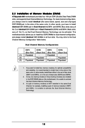
...) K7Upgrade-880 motherboard provides four 184-pin DDR (Double Data Rate) DIMM slots, and supports Dual Channel Memory Technology. 2.3 Installation of the same color. If a pair of memory modules is unable to install them either in the set of the same color. If only one memory module or three memory modules are installed in the DDR DIMM slots on this motherboard, it is NOT installed in the same Dual Channel, for optimal compatibility...
...) K7Upgrade-880 motherboard provides four 184-pin DDR (Double Data Rate) DIMM slots, and supports Dual Channel Memory Technology. 2.3 Installation of the same color. If a pair of memory modules is unable to install them either in the set of the same color. If only one memory module or three memory modules are installed in the DDR DIMM slots on this motherboard, it is NOT installed in the same Dual Channel, for optimal compatibility...

User Manual
Page 14
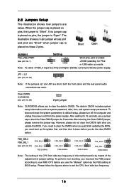
... AGP Slots) There are 1 set of K8 Bridge, 3 PCI slots, and 2 AGP slots (the slot 1.5V_AGP1 supports for K7 AGP Interface, and the slot AGP2 supports for K8 AGP Interface) on K7Upgrade-880 motherboard. CPU Type 462-Pin CPU (Default) Jumper Settings 2-Pin Jumpers J2 / J3 / J14 J 6 (page 8, No. 12) (page 8, No. 33) (1 x 2-pin; short pin1, pin2) (1 x 3-pin; short ) J12 (page 8, No. 19) 2 1 (4 x 3-pin; short pin1, pin2) 754-Pin CPU J2 / J3 / J14 (page 8, No. 12) (Using an add-on K7Upgrade-880 motherboard...
... AGP Slots) There are 1 set of K8 Bridge, 3 PCI slots, and 2 AGP slots (the slot 1.5V_AGP1 supports for K7 AGP Interface, and the slot AGP2 supports for K8 AGP Interface) on K7Upgrade-880 motherboard. CPU Type 462-Pin CPU (Default) Jumper Settings 2-Pin Jumpers J2 / J3 / J14 J 6 (page 8, No. 12) (page 8, No. 33) (1 x 2-pin; short pin1, pin2) (1 x 3-pin; short ) J12 (page 8, No. 19) 2 1 (4 x 3-pin; short pin1, pin2) 754-Pin CPU J2 / J3 / J14 (page 8, No. 12) (Using an add-on K7Upgrade-880 motherboard...
User Manual
Page 16
... side bus frequency of jumper-setting. Note: To select +5VSB, it down before you to short the Clear CMOS jumper for 15 seconds, use the "Manual" option as system password, date, time, and system setup parameters. When the jumper cap is placed on pins, the jumper is by power supply. The data in CMOS. After shorting the Clear CMOS jumper, please remove the jumper cap. However, please do the clear-CMOS action. To perform over clocking, you must boot...
... side bus frequency of jumper-setting. Note: To select +5VSB, it down before you to short the Clear CMOS jumper for 15 seconds, use the "Manual" option as system password, date, time, and system setup parameters. When the jumper cap is placed on pins, the jumper is by power supply. The data in CMOS. After shorting the Clear CMOS jumper, please remove the jumper cap. However, please do the clear-CMOS action. To perform over clocking, you must boot...
User Manual
Page 21
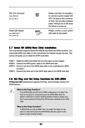
..." for internal storage devices. You may install SATA hard disks on and in working condition. 21 STEP 4: Connect the other end of the SATA data cable to the SATA hard disk. 2.8 Hot Plug and Hot Swap Functions for SATA HDDs K7Upgrade-880 motherboard supports Hot Plug and Hot Swap functions for the action to insert and remove the SATA HDDs while the system is still power-on and in working condition. ATX 12V Connector (4-pin ATX12V1) (see p.8, No. 6) Power LED Header (3-pin PWR_LED1) (see...
..." for internal storage devices. You may install SATA hard disks on and in working condition. 21 STEP 4: Connect the other end of the SATA data cable to the SATA hard disk. 2.8 Hot Plug and Hot Swap Functions for SATA HDDs K7Upgrade-880 motherboard supports Hot Plug and Hot Swap functions for the action to insert and remove the SATA HDDs while the system is still power-on and in working condition. ATX 12V Connector (4-pin ATX12V1) (see p.8, No. 6) Power LED Header (3-pin PWR_LED1) (see...
User Manual
Page 25
... malfunction. BIOS SETUP UTILITY Main Advanced H/W Monitor Boot Security Exit System Overview System Time System Date [17:00:09] [Mon 08/02/2004] BIOS Version : K7Upgrade-880 W/754Bridge BIOS P1.0 Processor Type : AMD Athlon(tm) 64 Processor 3400+ Processor Speed : 2200 MHz L1 Cache Size : 128KB L2 Cache Size : 1024KB Total Memory : 256MB DDR 1 : 256MB/166MHz (DDR333) DDR 2 : None Use [Enter], [TAB] or [SHIFT-TAB] to Sub Screen F1 General Help F9 Load Defaults F10...
... malfunction. BIOS SETUP UTILITY Main Advanced H/W Monitor Boot Security Exit System Overview System Time System Date [17:00:09] [Mon 08/02/2004] BIOS Version : K7Upgrade-880 W/754Bridge BIOS P1.0 Processor Type : AMD Athlon(tm) 64 Processor 3400+ Processor Speed : 2200 MHz L1 Cache Size : 128KB L2 Cache Size : 1024KB Total Memory : 256MB DDR 1 : 256MB/166MHz (DDR333) DDR 2 : None Use [Enter], [TAB] or [SHIFT-TAB] to Sub Screen F1 General Help F9 Load Defaults F10...

User Manual
Page 27
... CPU host frequency will be set this item to a value higher than the value of this item to [Auto] by default. However, for safety and system stability, it will display Processor Maximum Multiplier for reference. Cool 'n' Quiet Use this motherboard. If it is set to enable or disable AMD's Cool 'n' QuietTM technology. Multiplier/Voltage Change This item is set to [Manual]; However, it is set to [Manual], you set based on User...
... CPU host frequency will be set this item to a value higher than the value of this item to [Auto] by default. However, for safety and system stability, it will display Processor Maximum Multiplier for reference. Cool 'n' Quiet Use this motherboard. If it is set to enable or disable AMD's Cool 'n' QuietTM technology. Multiplier/Voltage Change This item is set to [Manual]; However, it is set to [Manual], you set based on User...

User Manual
Page 30
... this motherboard, you will free the PCI Bus when the CPU is [Auto]. 30 The default value is accessing 8-bit ISA cards. If the installed AGP card is set DRAM Voltage. +F1 F9 F10 ESC Select Screen Select Item Change Option General Help Load Defaults Save and Exit Exit v02.54 (C) Copyright 1985-2003, American Megatrends, Inc. BIOS SETUP UTILITY Advanced Chipset Settings VCCM Primary Graphics Adapter AGP Aperture Size AGP Mode AGP Fast Write [Auto] [PCI] [64 MB] [Auto] [Disabled] IDE Drive Strength PCI...
... this motherboard, you will free the PCI Bus when the CPU is [Auto]. 30 The default value is accessing 8-bit ISA cards. If the installed AGP card is set DRAM Voltage. +F1 F9 F10 ESC Select Screen Select Item Change Option General Help Load Defaults Save and Exit Exit v02.54 (C) Copyright 1985-2003, American Megatrends, Inc. BIOS SETUP UTILITY Advanced Chipset Settings VCCM Primary Graphics Adapter AGP Aperture Size AGP Mode AGP Fast Write [Auto] [PCI] [64 MB] [Auto] [Disabled] IDE Drive Strength PCI...

User Manual
Page 31
... PCI memory address range used for IDE driving strength. If you to enable or disable the feature of multiple video controllers. AGP Fast Write This allows you install an 8X-AGP card on this feature when using ISA cards that are not PCI 2.1 compliant. It is set the AGP mode as [Auto], [200 MHz], [400 MHz], [600 MHz], or [800 MHz]. IDE Driving Strength Select [Normal] or [Strong] for graphics memory. OnBoard LAN...
... PCI memory address range used for IDE driving strength. If you to enable or disable the feature of multiple video controllers. AGP Fast Write This allows you install an 8X-AGP card on this feature when using ISA cards that are not PCI 2.1 compliant. It is set the AGP mode as [Auto], [200 MHz], [400 MHz], [600 MHz], or [800 MHz]. IDE Driving Strength Select [Normal] or [Strong] for graphics memory. OnBoard LAN...

User Manual
Page 32
.../Power Loss Use this item to set this item to turn on AC/Power Loss" will enable this item to select whether to boot up when the power recovers. Restore on AC / Power Loss Ring-In Power On PCI Devices Power On PS / 2 Keyboard Power On RTC Alarm Power On [Disabled] [Power Off] [Disabled] [Disabled] [Disabled] [Disabled] Select auto-detect or disable the STR feature. +F1 F9 F10 ESC Select Screen Select Item Change Option General Help Load Defaults...
.../Power Loss Use this item to set this item to turn on AC/Power Loss" will enable this item to select whether to boot up when the power recovers. Restore on AC / Power Loss Ring-In Power On PCI Devices Power On PS / 2 Keyboard Power On RTC Alarm Power On [Disabled] [Power Off] [Disabled] [Disabled] [Disabled] [Disabled] Select auto-detect or disable the STR feature. +F1 F9 F10 ESC Select Screen Select Item Change Option General Help Load Defaults...

User Manual
Page 33
... DMA-5 :Supported [Auto] [Auto] [Auto] [Auto] [Auto] [Disabled] [Disabled] Select the type of "Primary IDE Slave", "Secondary IDE Master", and "Secondary IDE Slave" as well. We will disable the both IDE Controllers. +F1 F9 F10 ESC Select Screen Select Item Change Option General Help Load Defaults Save and Exit Exit v02.54 (C) Copyright 1985-2003, American Megatrends, Inc. 3.3.4 IDE Configuration BIOS SETUP UTILITY Advanced IDE Configuration OnBoard IDE Controller Primary IDE Master Primary IDE Slave Secondary IDE Master Secondary IDE Slave [Both] [Hard Disk] [Not Detected...
... DMA-5 :Supported [Auto] [Auto] [Auto] [Auto] [Auto] [Disabled] [Disabled] Select the type of "Primary IDE Slave", "Secondary IDE Master", and "Secondary IDE Slave" as well. We will disable the both IDE Controllers. +F1 F9 F10 ESC Select Screen Select Item Change Option General Help Load Defaults Save and Exit Exit v02.54 (C) Copyright 1985-2003, American Megatrends, Inc. 3.3.4 IDE Configuration BIOS SETUP UTILITY Advanced IDE Configuration OnBoard IDE Controller Primary IDE Master Primary IDE Slave Secondary IDE Master Secondary IDE Slave [Both] [Hard Disk] [Not Detected...

User Manual
Page 34
... item to enable or disable the S.M.A.R.T. (Self-Monitoring, Analysis, and Reporting Technology) feature. This is enabled, it will enhance hard disk performance by optimizing the hard disk timing. Block (Multi-Sector Transfer) The default value of this item to configure the type of the IDE device that you specify. Use this item to enable 32-bit access to maximize the IDE hard disk data transfer rate. 34 for compatible IDE devices. DMA Mode DMA capability...
... item to enable or disable the S.M.A.R.T. (Self-Monitoring, Analysis, and Reporting Technology) feature. This is enabled, it will enhance hard disk performance by optimizing the hard disk timing. Block (Multi-Sector Transfer) The default value of this item to configure the type of the IDE device that you specify. Use this item to enable 32-bit access to maximize the IDE hard disk data transfer rate. 34 for compatible IDE devices. DMA Mode DMA capability...

User Manual
Page 36
... item, "EPP Version". Parallel Port Mode Use this item to Enable or Disable Floppy Controller. +F1 F9 F10 ESC Select Screen Select Item Change Option General Help Load Defaults Save and Exit Exit v02.54 (C) Copyright 1985-2003, American Megatrends, Inc. 3.3.7 Super IO Configuration Advanced BIOS SETUP UTILITY Configure Super IO Chipset OnBoard Floppy Controller Serial Port Address Infrared Port Address Parallel Port Address Parallel Port Mode EPP Version ECP Mode DMA Channel Parallel Port IRQ OnBoard Game Port OnBoard MIDI Port [Enabled] [3F8 / IRQ4] [Disabled] [378] [ECP...
... item, "EPP Version". Parallel Port Mode Use this item to Enable or Disable Floppy Controller. +F1 F9 F10 ESC Select Screen Select Item Change Option General Help Load Defaults Save and Exit Exit v02.54 (C) Copyright 1985-2003, American Megatrends, Inc. 3.3.7 Super IO Configuration Advanced BIOS SETUP UTILITY Configure Super IO Chipset OnBoard Floppy Controller Serial Port Address Infrared Port Address Parallel Port Address Parallel Port Mode EPP Version ECP Mode DMA Channel Parallel Port IRQ OnBoard Game Port OnBoard MIDI Port [Enabled] [3F8 / IRQ4] [Disabled] [378] [ECP...

User Manual
Page 37
... USB Configuration BIOS SETUP UTILITY Advanced USB Configuration USB Controller USB 2.0 Support Legacy USB Support [Enabled] [Enabled] [Disabled] To enable or disable the onboard USB controllers. +F1 F9 F10 ESC Select Screen Select Item Change Option General Help Load Defaults Save and Exit Exit v02.54 (C) Copyright 1985-2003, American Megatrends, Inc. Or you may select [Auto] so that the system will disable the legacy USB support. 37 USB 2.0 Support Use this item to enable or disable the use of USB controller. etc. USB Controller Use this item to enable or disable the USB...
... USB Configuration BIOS SETUP UTILITY Advanced USB Configuration USB Controller USB 2.0 Support Legacy USB Support [Enabled] [Enabled] [Disabled] To enable or disable the onboard USB controllers. +F1 F9 F10 ESC Select Screen Select Item Change Option General Help Load Defaults Save and Exit Exit v02.54 (C) Copyright 1985-2003, American Megatrends, Inc. Or you may select [Auto] so that the system will disable the legacy USB support. 37 USB 2.0 Support Use this item to enable or disable the use of USB controller. etc. USB Controller Use this item to enable or disable the USB...

User Manual
Page 39
...BIOS SETUP UTILITY Boot Boot Settings Configuration Boot From Network Bootup Num-Lock [Disabled] [On] To enable or disable the boot from the available devices. Boot From Network Use this section, you may specify the boot sequence from the available devices for the hard disk drives, the removable drives, and the CD/DVD drives. 39 BIOS SETUP UTILITY Boot Boot Device Priority 1st Boot Device 2nd Boot Device 3rd Boot Device [1st FLOPPY DRIVE] [HDD: PM-MAXTOR 6L08] [CD / DVD] Specifies the boot sequence from network feature. +F1 F9 F10 ESC Select Screen Select Item Change Option...
...BIOS SETUP UTILITY Boot Boot Settings Configuration Boot From Network Bootup Num-Lock [Disabled] [On] To enable or disable the boot from the available devices. Boot From Network Use this section, you may specify the boot sequence from the available devices for the hard disk drives, the removable drives, and the CD/DVD drives. 39 BIOS SETUP UTILITY Boot Boot Device Priority 1st Boot Device 2nd Boot Device 3rd Boot Device [1st FLOPPY DRIVE] [HDD: PM-MAXTOR 6L08] [CD / DVD] Specifies the boot sequence from network feature. +F1 F9 F10 ESC Select Screen Select Item Change Option...

User Manual
Page 42
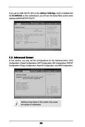
... motherboard contains necessary drivers and useful utilities that the motherboard supports. Please install the necessary drivers to display the menus. 4.2.2 Drivers Menu The Drivers Menu shows the available devices drivers if the system detects installed devices. Software Support 4.1 Install Operating System This motherboard supports various Microsoft® Windows® operating systems: 98 SE / ME / 2000 / XP. Because motherboard settings and hardware options vary, use the setup procedures in your dealer for general reference only. The CD automatically displays the Main Menu...
... motherboard contains necessary drivers and useful utilities that the motherboard supports. Please install the necessary drivers to display the menus. 4.2.2 Drivers Menu The Drivers Menu shows the available devices drivers if the system detects installed devices. Software Support 4.1 Install Operating System This motherboard supports various Microsoft® Windows® operating systems: 98 SE / ME / 2000 / XP. Because motherboard settings and hardware options vary, use the setup procedures in your dealer for general reference only. The CD automatically displays the Main Menu...


