User Manual
Page 6
...) - 1 x Floppy connector - 1 x IR header - Northbridge: SiS® 741GX - DirectX 7 - resolution up to -Use USB 2.0 Ports - 1 x RJ-45 LAN Port with max. Integrated Mirage Graphics - Max. Socket 462 for AMD Sempron / Athlon / Athlon XP / Duron Processors -
...) - 1 x Floppy connector - 1 x IR header - Northbridge: SiS® 741GX - DirectX 7 - resolution up to -Use USB 2.0 Ports - 1 x RJ-45 LAN Port with max. Integrated Mirage Graphics - Max. Socket 462 for AMD Sempron / Athlon / Athlon XP / Duron Processors -

User Manual
Page 10
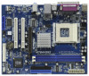
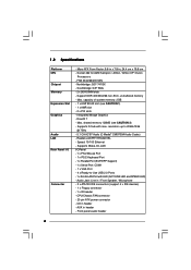
1.3 Motherboard Layout 12 3 4 19.8cm (7.8-in) 1 PS2_USB_PWR1 PS2 Mouse PS2 Keyboard CPU_FAN1 5 6 Designed in Taipei K7S41GX2 DDR1 (64 bit, 184-pin module) DDR2 (64 bit, 184-pin module) ATXPWR1 24.4cm (9.6-in) PARALLEL PORT COM1 VGA1 28 27 USB 2.0 ... 963L CHA_FAN1 PLED PWRBTN SPEAKER1 PANEL 1 1 1 HDLED RST 20 1918 17 16 15 14 13 9 10 11 12 1 PS2_USB_PWR1 Jumper 2 CPU Fan Connector (CPU_FAN1) 3 CPU Socket 4 North Bridge Controller 5 184-pin DDR DIMM Slots (DDR 1- 2) 6 ATX Power Connector (ATXPWR1) 7 Secondary IDE Connector (IDE2, Black) 8 Primary IDE Connector (IDE1, Blue...
1.3 Motherboard Layout 12 3 4 19.8cm (7.8-in) 1 PS2_USB_PWR1 PS2 Mouse PS2 Keyboard CPU_FAN1 5 6 Designed in Taipei K7S41GX2 DDR1 (64 bit, 184-pin module) DDR2 (64 bit, 184-pin module) ATXPWR1 24.4cm (9.6-in) PARALLEL PORT COM1 VGA1 28 27 USB 2.0 ... 963L CHA_FAN1 PLED PWRBTN SPEAKER1 PANEL 1 1 1 HDLED RST 20 1918 17 16 15 14 13 9 10 11 12 1 PS2_USB_PWR1 Jumper 2 CPU Fan Connector (CPU_FAN1) 3 CPU Socket 4 North Bridge Controller 5 184-pin DDR DIMM Slots (DDR 1- 2) 6 ATX Power Connector (ATXPWR1) 7 Secondary IDE Connector (IDE2, Black) 8 Primary IDE Connector (IDE1, Blue...

User Manual
Page 12
... damaging the motherboard components due to static electricity, NEVER place your chassis to the motherboard, peripherals, and/or components. 12 Chapter 2 Installation K7S41GX2 is detached from the wall socket before touching any component, place it . Hold components by the edges and do so may cause severe damage to ensure that comes with...
... damaging the motherboard components due to static electricity, NEVER place your chassis to the motherboard, peripherals, and/or components. 12 Chapter 2 Installation K7S41GX2 is detached from the wall socket before touching any component, place it . Hold components by the edges and do so may cause severe damage to ensure that comes with...
User Manual
Page 13
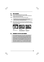
... CPU Fan and Heatsink This motherboard adopts 462-pin CPU socket to improve heat dissipation. Step 3. Carefully insert the CPU into the socket to the instruction manuals of the socket lever. 2.1 Step 1. DO NOT force the CPU into the socket until it is in one correct orientation. Make sure that...its marked corner matches the base of the CPU fan and the heatsink. 13 The lever clicks on the socket while you push down the socket lever to a 90o angle. CPU Installation Unlock the socket by lifting the lever up to secure the CPU. Position the CPU directly above the...
... CPU Fan and Heatsink This motherboard adopts 462-pin CPU socket to improve heat dissipation. Step 3. Carefully insert the CPU into the socket to the instruction manuals of the socket lever. 2.1 Step 1. DO NOT force the CPU into the socket until it is in one correct orientation. Make sure that...its marked corner matches the base of the CPU fan and the heatsink. 13 The lever clicks on the socket while you push down the socket lever to a 90o angle. CPU Installation Unlock the socket by lifting the lever up to secure the CPU. Position the CPU directly above the...

Quick Installation Guide
Page 2
Motherboard Layout English 1 PS2_USB_PWR1 Jumper 2 CPU Fan Connector (CPU_FAN1) 3 CPU Socket 4 North Bridge Controller 5 184-pin DDR DIMM Slots (DDR 1- 2) 6 ATX Power Connector (ATXPWR1) 7 Secondary IDE Connector (IDE2, Black) 8 Primary IDE Connector (IDE1, Blue) 9 AGP Slot (1....) 24 PCI Slots (PCI 1- 2) 25 FSB Select Jumpers (FSB_SEL0/FSB_SEL1) 26 Internal Audio Connector: CD1 (Black) 27 Internal Audio Connector: AUX1 (White) 28 J1 Jumpers 2 ASRock K7S41GX2 Motherboard
Motherboard Layout English 1 PS2_USB_PWR1 Jumper 2 CPU Fan Connector (CPU_FAN1) 3 CPU Socket 4 North Bridge Controller 5 184-pin DDR DIMM Slots (DDR 1- 2) 6 ATX Power Connector (ATXPWR1) 7 Secondary IDE Connector (IDE2, Black) 8 Primary IDE Connector (IDE1, Blue) 9 AGP Slot (1....) 24 PCI Slots (PCI 1- 2) 25 FSB Select Jumpers (FSB_SEL0/FSB_SEL1) 26 Internal Audio Connector: CD1 (Black) 27 Internal Audio Connector: AUX1 (White) 28 J1 Jumpers 2 ASRock K7S41GX2 Motherboard

Quick Installation Guide
Page 5
...shared memory 128MB (see CAUTION 1) - 1 x AMR slot - 2 x PCI slots - Speed: 10/100 Ethernet - Front panel audio header English 5 ASRock K7S41GX2 Motherboard FSB 333/266/200 MHz - Max. CPU/Chassis FAN connector - 20 pin ATX power connector - AUX in header - Supports Wake-On-LAN I... Ready-to 2048x1536 @ 75Hz - 5.1 CH AC'97 Audio (C-Media® CMI9739A Audio Codec) - Support DDR 400/333/266 non-ECC, un-buffered memory - Socket 462 for AMD Sempron / Athlon / Athlon XP / Duron Processors - Southbridge: SiS® 963L - 2 x DDR DIMM slots - capacity of system memory: 2GB ...
...shared memory 128MB (see CAUTION 1) - 1 x AMR slot - 2 x PCI slots - Speed: 10/100 Ethernet - Front panel audio header English 5 ASRock K7S41GX2 Motherboard FSB 333/266/200 MHz - Max. CPU/Chassis FAN connector - 20 pin ATX power connector - AUX in header - Supports Wake-On-LAN I... Ready-to 2048x1536 @ 75Hz - 5.1 CH AC'97 Audio (C-Media® CMI9739A Audio Codec) - Support DDR 400/333/266 non-ECC, un-buffered memory - Socket 462 for AMD Sempron / Athlon / Athlon XP / Duron Processors - Southbridge: SiS® 963L - 2 x DDR DIMM slots - capacity of system memory: 2GB ...

Quick Installation Guide
Page 9
...To avoid damaging the motherboard components due to static electricity, NEVER place your chassis to the motherboard, peripherals, and/or components. 9 ASRock K7S41GX2 Motherboard English Hold components by the edges and do so may cause severe damage to ensure that the power is switched off or ...Failure to use a grounded wrist strap or touch a safety grounded object before touching any motherboard settings. 1. Installation K7S41GX2 is detached from the wall socket before you uninstall any component, ensure that the motherboard fits into it on the carpet or the like. Also ...
...To avoid damaging the motherboard components due to static electricity, NEVER place your chassis to the motherboard, peripherals, and/or components. 9 ASRock K7S41GX2 Motherboard English Hold components by the edges and do so may cause severe damage to ensure that the power is switched off or ...Failure to use a grounded wrist strap or touch a safety grounded object before touching any motherboard settings. 1. Installation K7S41GX2 is detached from the wall socket before you uninstall any component, ensure that the motherboard fits into it on the carpet or the like. Also ...

Quick Installation Guide
Page 10
... CPU into the socket until it is in place, press it firmly on the side tab to secure the CPU. Make sure that its marked corner matches the base of the pins. The CPU fits only in good contact with each other. English 10 ASRock K7S41GX2 Motherboard Step 4.... For proper installation, please kindly refer to a 90o angle. Unlock the socket by lifting the lever up to the instruction manuals of CPU Fan and Heatsink This motherboard adopts...
... CPU into the socket until it is in place, press it firmly on the side tab to secure the CPU. Make sure that its marked corner matches the base of the pins. The CPU fits only in good contact with each other. English 10 ASRock K7S41GX2 Motherboard Step 4.... For proper installation, please kindly refer to a 90o angle. Unlock the socket by lifting the lever up to the instruction manuals of CPU Fan and Heatsink This motherboard adopts...