
User Manual
Page 2
... and subject to infringe. "Perchlorate Material-special handling may apply, see www.dtsc.ca.gov/hazardouswaste/perchlorate" ASRock Website: http://www.asrock.com 2 Products and corporate names appearing in this manual may or may not be registered trademarks or copyrights ...related regulations in advance. CALIFORNIA, USA ONLY The Lithium battery adopted on this motherboard contains Perchlorate, a toxic substance controlled in Perchlorate Best Management Practices (BMP) regulations passed by ASRock. Disclaimer: Specifications and information contained in this manual are used only for ...
... and subject to infringe. "Perchlorate Material-special handling may apply, see www.dtsc.ca.gov/hazardouswaste/perchlorate" ASRock Website: http://www.asrock.com 2 Products and corporate names appearing in this manual may or may not be registered trademarks or copyrights ...related regulations in advance. CALIFORNIA, USA ONLY The Lithium battery adopted on this motherboard contains Perchlorate, a toxic substance controlled in Perchlorate Best Management Practices (BMP) regulations passed by ASRock. Disclaimer: Specifications and information contained in this manual are used only for ...

User Manual
Page 3
... Configuration 35 3.5 Hardware Health Event Monitoring Screen 36 3.6 Boot Screen 36 3.6.1 Boot Settings Configuration 37 3.7 Security Screen 38 3.8 Exit Screen 39 3 Introduction 5 1.1 Package Contents 5 1.2 Specifications 6 1.3 Motherboard Layout 10 1.4 I/O Panel 11 2 . Contents 1 . Installation 12 Pre-installation Precautions 12 2.1 CPU Installation 13 2.2 Installation of CPU Fan and Heatsink 13 2.3 Installation of Memory Modules...
... Configuration 35 3.5 Hardware Health Event Monitoring Screen 36 3.6 Boot Screen 36 3.6.1 Boot Settings Configuration 37 3.7 Security Screen 38 3.8 Exit Screen 39 3 Introduction 5 1.1 Package Contents 5 1.2 Specifications 6 1.3 Motherboard Layout 10 1.4 I/O Panel 11 2 . Contents 1 . Installation 12 Pre-installation Precautions 12 2.1 CPU Installation 13 2.2 Installation of CPU Fan and Heatsink 13 2.3 Installation of Memory Modules...

User Manual
Page 5
... manual will be subject to this manual occur, the updated version will be available on ASRock website as well. www.asrock.com/support/index.asp 1.1 Package Contents One ASRock K7S41GX2 Motherboard (Micro ATX Form Factor: 9.6-in x 7.8-in Floppy Drive One I/O Panel Shield 5.../100/133 IDE Ribbon Cable One Ribbon Cable for purchasing ASRock K7S41GX2 motherboard, a reliable motherboard produced under ASRock's consistently stringent quality control. It delivers excellent performance with robust design conforming to ASRock's commitment to quality and endurance. Introduction Thank you require ...
... manual will be subject to this manual occur, the updated version will be available on ASRock website as well. www.asrock.com/support/index.asp 1.1 Package Contents One ASRock K7S41GX2 Motherboard (Micro ATX Form Factor: 9.6-in x 7.8-in Floppy Drive One I/O Panel Shield 5.../100/133 IDE Ribbon Cable One Ribbon Cable for purchasing ASRock K7S41GX2 motherboard, a reliable motherboard produced under ASRock's consistently stringent quality control. It delivers excellent performance with robust design conforming to ASRock's commitment to quality and endurance. Introduction Thank you require ...

User Manual
Page 8
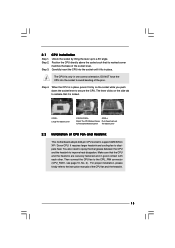
... XP SP1 or SP2 / 2000 SP4. 4. Power Management for the latest information. 3. Please check page 24 for details. 7. Although this motherboard offers stepless control, it back again. Frequencies other than the recommended CPU bus frequencies may cause permanent damage! 2. The CPU host frequency of ...this utility, you can press key during the POST or press key to BIOS setup menu to perform over clocking. ASRock Instant Flash is determined by the chipset vendor and is not recommended to perform over clocking. To improve heat dissipation, remember to ...
... XP SP1 or SP2 / 2000 SP4. 4. Power Management for the latest information. 3. Please check page 24 for details. 7. Although this motherboard offers stepless control, it back again. Frequencies other than the recommended CPU bus frequencies may cause permanent damage! 2. The CPU host frequency of ...this utility, you can press key during the POST or press key to BIOS setup menu to perform over clocking. ASRock Instant Flash is determined by the chipset vendor and is not recommended to perform over clocking. To improve heat dissipation, remember to ...

User Manual
Page 9
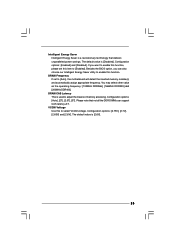
... for Energy Using Product, was a provision regulated by European Union to Intel's suggestion, the EuP ready power supply must meet EuP standard, an EuP ready motherboard and an EuP ready power supply are required. For EuP ready power supply selection, we recommend you checking with the power supply manufacturer for the...
... for Energy Using Product, was a provision regulated by European Union to Intel's suggestion, the EuP ready power supply must meet EuP standard, an EuP ready motherboard and an EuP ready power supply are required. For EuP ready power supply selection, we recommend you checking with the power supply manufacturer for the...

User Manual
Page 10
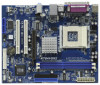
1.3 Motherboard Layout 12 3 4 19.8cm (7.8-in) 1 PS2_USB_PWR1 PS2 Mouse PS2 Keyboard CPU_FAN1 5 6 Designed in Taipei K7S41GX2 DDR1 (64 bit, 184-pin module) DDR2 (64 bit, 184-pin module) ATXPWR1 24.4cm (9.6-in) PARALLEL PORT COM1 VGA1 28 27 USB 2.0 T: USB2 B: USB3 ...
1.3 Motherboard Layout 12 3 4 19.8cm (7.8-in) 1 PS2_USB_PWR1 PS2 Mouse PS2 Keyboard CPU_FAN1 5 6 Designed in Taipei K7S41GX2 DDR1 (64 bit, 184-pin module) DDR2 (64 bit, 184-pin module) ATXPWR1 24.4cm (9.6-in) PARALLEL PORT COM1 VGA1 28 27 USB 2.0 T: USB2 B: USB3 ...

User Manual
Page 12
... and/or components. 12 Failure to do not touch the ICs. 4. Chapter 2 Installation K7S41GX2 is detached from the wall socket before touching any component, place it . Pre-installation Precautions Take note of your motherboard directly on a grounded antistatic pad or in the bag that the power is switched off ...or the power cord is a Micro ATX form factor (9.6-in x 7.8-in, 24.4 cm x 19.8 cm) motherboard. Hold components by the edges and do so may cause severe damage to use a grounded wrist strap or touch a safety grounded object before you uninstall...
... and/or components. 12 Failure to do not touch the ICs. 4. Chapter 2 Installation K7S41GX2 is detached from the wall socket before touching any component, place it . Pre-installation Precautions Take note of your motherboard directly on a grounded antistatic pad or in the bag that the power is switched off ...or the power cord is a Micro ATX form factor (9.6-in x 7.8-in, 24.4 cm x 19.8 cm) motherboard. Hold components by the edges and do so may cause severe damage to use a grounded wrist strap or touch a safety grounded object before you uninstall...
User Manual
Page 13
... socket lever to support AMD Athlon XP / Duron CPU. For proper installation, please kindly refer to the instruction manuals of CPU Fan and Heatsink This motherboard adopts 462-pin CPU socket to secure the CPU. The CPU fits only in good contact with each other. You also need to spray thermal...
... socket lever to support AMD Athlon XP / Duron CPU. For proper installation, please kindly refer to the instruction manuals of CPU Fan and Heatsink This motherboard adopts 462-pin CPU socket to secure the CPU. The CPU fits only in good contact with each other. You also need to spray thermal...

User Manual
Page 14
...cause permanent damage to disconnect power supply before adding or removing DIMMs or the system components. Step 3. 2.3 Installation of Memory Modules (DIMM) K7S41GX2 motherboard provides two 184-pin DDR (Double Data Rate) DIMM slots. Unlock a DIMM slot by pressing the retaining clips outward. Please make sure to the... motherboard and the DIMM if you force the DIMM into the slot until the retaining clips at incorrect orientation. Align a DIMM on the slot...
...cause permanent damage to disconnect power supply before adding or removing DIMMs or the system components. Step 3. 2.3 Installation of Memory Modules (DIMM) K7S41GX2 motherboard provides two 184-pin DDR (Double Data Rate) DIMM slots. Unlock a DIMM slot by pressing the retaining clips outward. Please make sure to the... motherboard and the DIMM if you force the DIMM into the slot until the retaining clips at incorrect orientation. Align a DIMM on the slot...

User Manual
Page 15
... with the graphics card vendors. Fasten the card to the chassis with v.92 Modem functionality. AMR slot: The AMR slot is completely seated on K7S41GX2 motherboard. It may cause permanent damage! For the voltage information of the expansion card and make sure that can securely fasten the inserted graphics card. Step... to install a graphics card. AGP slot: The AGP slot is already installed in a chassis). Please do NOT use . Please read the documentation of your motherboard is used to insert an ASRock MR card (optional) with screws. Step 6. Replace the system cover. 15
... with the graphics card vendors. Fasten the card to the chassis with v.92 Modem functionality. AMR slot: The AMR slot is completely seated on K7S41GX2 motherboard. It may cause permanent damage! For the voltage information of the expansion card and make sure that can securely fasten the inserted graphics card. Step... to install a graphics card. AGP slot: The AGP slot is already installed in a chassis). Please do NOT use . Please read the documentation of your motherboard is used to insert an ASRock MR card (optional) with screws. Step 6. Replace the system cover. 15

User Manual
Page 16
... 2_3 FSB_SEL1 2_3 FSB_SEL0 FSB 266MHz Description 1_2 FSB_SEL1 1_2 FSB_SEL0 FSB 333MHz Note: The setting of the CPU front side bus frequency of this motherboard is by power supply. 16 Note: To select +5VSB, it requires 2 Amp and higher standby current provided by power supply. You must set the CPU...
... 2_3 FSB_SEL1 2_3 FSB_SEL0 FSB 266MHz Description 1_2 FSB_SEL1 1_2 FSB_SEL0 FSB 333MHz Note: The setting of the CPU front side bus frequency of this motherboard is by power supply. 16 Note: To select +5VSB, it requires 2 Amp and higher standby current provided by power supply. You must set the CPU...
User Manual
Page 19
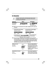
USB 2.0 Connector (9-pin USB45) (see p.10 No. 7) PIN1 IDE1 PIN1 IDE2 connect the blue end connect the black end to the motherboard to the instruction of the motherboard! Placing jumper caps over these connectors. DO NOT place jumper caps over the connectors will cause permanent damage of your hard disk drive to the... No. 19) IRTX +5V DUMMY 1 GND IRRX This connector supports an optional wireless transmitting and receiving infrared module. 19 2.6 Connectors Connectors are not sufficient, this motherboard, please set the IDE device as "Master".
USB 2.0 Connector (9-pin USB45) (see p.10 No. 7) PIN1 IDE1 PIN1 IDE2 connect the blue end connect the black end to the motherboard to the instruction of the motherboard! Placing jumper caps over these connectors. DO NOT place jumper caps over the connectors will cause permanent damage of your hard disk drive to the... No. 19) IRTX +5V DUMMY 1 GND IRRX This connector supports an optional wireless transmitting and receiving infrared module. 19 2.6 Connectors Connectors are not sufficient, this motherboard, please set the IDE device as "Master".

User Manual
Page 22
... chassis. You may run the BIOS SETUP UTILITY when you see on your system. You may also restart by pressing the reset button on the motherboard stores the BIOS SETUP UTILITY. Because the BIOS software is constantly being updated, the following BIOS setup screens and descriptions are for reference purpose only...
... chassis. You may run the BIOS SETUP UTILITY when you see on your system. You may also restart by pressing the reset button on the motherboard stores the BIOS SETUP UTILITY. Because the BIOS software is constantly being updated, the following BIOS setup screens and descriptions are for reference purpose only...

User Manual
Page 24
... DRAM CAS Latency VCCM Voltage [By Jumper] [166] [Auto] [Enabled] [3] [Normal] [Disabled] [Auto] [Auto] [2.6V] Would you use this motherboard determined by the jumper-setting. [Manual] This allows user to enable "Over Vcore Voltage" feature. CPU Host Frequency [By Jumper] It is a read-only ... host frequency. However, because the CPU host frequency of Boot Failure Guard Count. Boot Failure Guard Enable or disable the feature of this motherboard is [Disabled]. Select Screen Select Item Enter Go to set up overclocking features. The default value is determined by 3% or 6%. 3.3 ...
... DRAM CAS Latency VCCM Voltage [By Jumper] [166] [Auto] [Enabled] [3] [Normal] [Disabled] [Auto] [Auto] [2.6V] Would you use this motherboard determined by the jumper-setting. [Manual] This allows user to enable "Over Vcore Voltage" feature. CPU Host Frequency [By Jumper] It is a read-only ... host frequency. However, because the CPU host frequency of Boot Failure Guard Count. Boot Failure Guard Enable or disable the feature of this motherboard is [Disabled]. Select Screen Select Item Enter Go to set up overclocking features. The default value is determined by 3% or 6%. 3.3 ...
User Manual
Page 25
... a revolutionary technology that not all the DDR DIMMs can also choose our Intelligent Energy Saver utility to enable this function, please set to [Auto], the motherboard will detect the inserted memory module(s) and automatically assign appropriate frequency. If you can support CAS latency=3T. DRAM CAS Latency This is used to...
... a revolutionary technology that not all the DDR DIMMs can also choose our Intelligent Energy Saver utility to enable this function, please set to [Auto], the motherboard will detect the inserted memory module(s) and automatically assign appropriate frequency. If you can support CAS latency=3T. DRAM CAS Latency This is used to...

User Manual
Page 27
... recommended to select this option, which displays the actual frequency of this motherboard determined by 3% or 6%. Boot Failure Guard Count Enable or disable the feature of Boot Failure Guard. The default value is not recommended to your AMD ... CPU damage. 27 Boot Failure Guard Enable or disable the feature of Boot Failure Guard Count. Over Vcore Voltage This feature allows you use this motherboard. CPU Host Frequency [By Jumper] It is determined by the jumpersetting, you thoroughly know the feature. Doing so may cause problems during operation. Spread Spectrum...
... recommended to select this option, which displays the actual frequency of this motherboard determined by 3% or 6%. Boot Failure Guard Count Enable or disable the feature of Boot Failure Guard. The default value is not recommended to your AMD ... CPU damage. 27 Boot Failure Guard Enable or disable the feature of Boot Failure Guard Count. Over Vcore Voltage This feature allows you use this motherboard. CPU Host Frequency [By Jumper] It is determined by the jumpersetting, you thoroughly know the feature. Doing so may cause problems during operation. Spread Spectrum...

User Manual
Page 36
... Monitoring Screen In this section, it allows you to monitor the status of the hardware on your system, including the parameters of the CPU temperature, motherboard temperature, CPU fan speed, chassis fan speed, and the critical voltage.
... Monitoring Screen In this section, it allows you to monitor the status of the hardware on your system, including the parameters of the CPU temperature, motherboard temperature, CPU fan speed, chassis fan speed, and the critical voltage.

User Manual
Page 40
... "AUTORUN" is enabled in your dealer for general reference only. Because motherboard settings and hardware options vary, use the setup procedures in the Support CD to visit ASRock's website at http://www.asrock.com; Click on the file ASSETUP.EXE from the BIN folder in... wizard to know more information. 4.2 Support CD Information The Support CD that came with the motherboard contains necessary drivers and useful utilities that the motherboard supports. or you need to contact ASRock or want to install it. 4.2.4 Contact Information If you may contact your computer. Chapter 4...
... "AUTORUN" is enabled in your dealer for general reference only. Because motherboard settings and hardware options vary, use the setup procedures in the Support CD to visit ASRock's website at http://www.asrock.com; Click on the file ASSETUP.EXE from the BIN folder in... wizard to know more information. 4.2 Support CD Information The Support CD that came with the motherboard contains necessary drivers and useful utilities that the motherboard supports. or you need to contact ASRock or want to install it. 4.2.4 Contact Information If you may contact your computer. Chapter 4...

Quick Installation Guide
Page 1
... for any errors or omissions that may cause undesired operation. ASRock assumes no event shall ASRock, its directors, officers, employees, or agents be constructed as a commitment by ASRock. All rights reserved. 1 ASRock K7S41GX2 Motherboard English With respect to the contents of this installation guide may... fitness for a particular purpose. Products and corporate names appearing in this motherboard contains Perchlorate, a toxic substance controlled in advance. This device complies with Part 15 of ASRock Inc. CALIFORNIA, USA ONLY The Lithium battery adopted on this guide may...
... for any errors or omissions that may cause undesired operation. ASRock assumes no event shall ASRock, its directors, officers, employees, or agents be constructed as a commitment by ASRock. All rights reserved. 1 ASRock K7S41GX2 Motherboard English With respect to the contents of this installation guide may... fitness for a particular purpose. Products and corporate names appearing in this motherboard contains Perchlorate, a toxic substance controlled in advance. This device complies with Part 15 of ASRock Inc. CALIFORNIA, USA ONLY The Lithium battery adopted on this guide may...

Quick Installation Guide
Page 2
Motherboard Layout English 1 PS2_USB_PWR1 Jumper 2 CPU Fan Connector (CPU_FAN1) 3 CPU Socket 4 North Bridge Controller 5 184-pin DDR DIMM Slots (DDR 1- 2) 6 ATX Power Connector (ATXPWR1) 7 Secondary IDE ...) 24 PCI Slots (PCI 1- 2) 25 FSB Select Jumpers (FSB_SEL0/FSB_SEL1) 26 Internal Audio Connector: CD1 (Black) 27 Internal Audio Connector: AUX1 (White) 28 J1 Jumpers 2 ASRock K7S41GX2 Motherboard
Motherboard Layout English 1 PS2_USB_PWR1 Jumper 2 CPU Fan Connector (CPU_FAN1) 3 CPU Socket 4 North Bridge Controller 5 184-pin DDR DIMM Slots (DDR 1- 2) 6 ATX Power Connector (ATXPWR1) 7 Secondary IDE ...) 24 PCI Slots (PCI 1- 2) 25 FSB Select Jumpers (FSB_SEL0/FSB_SEL1) 26 Internal Audio Connector: CD1 (Black) 27 Internal Audio Connector: AUX1 (White) 28 J1 Jumpers 2 ASRock K7S41GX2 Motherboard

